Programmable ring light
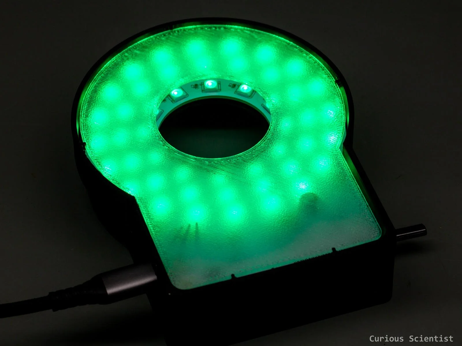
In this article, I show you how I designed and built my custom, programmable ring light. I wanted to get a more flexible light source that I could use for my macro camera setup, so I decided to design and build one from scratch. This module not only provides a lot of light where it is needed, but the light can be customised to a great extent. Brightness, colour, and even the lit pixels (individual LEDs) can be meticulously controlled. The device is USB-C-powered, and it is controlled by a rotary encoder and a small 128×32 pixel OLED display. The LEDs are the classic WS2812B “Neopixel” RGB LEDs, and they are controlled by a CH32X035G8U6 microcontroller using my tricky SPI library. The device received a 3D-printed enclosure, so it almost looks like a proper product.
Circuit design
I combined experience from several earlier projects in this device.
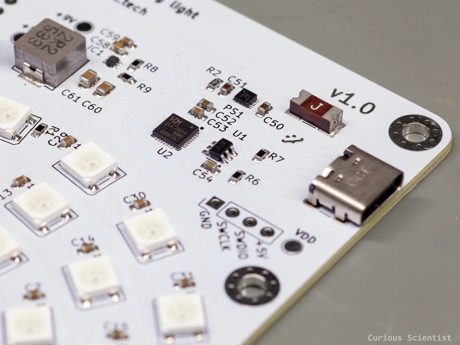
I used the same CH32X035G8U6 microcontroller that I used in my recent 100 W USB PD power supply project. In fact, I borrowed the whole design starting from the USB connector, all the way to the chip. So, the USB connector, the ESD protection chip and the components around it are all, let’s say, well-proven components, and their design worked well in the previous project.
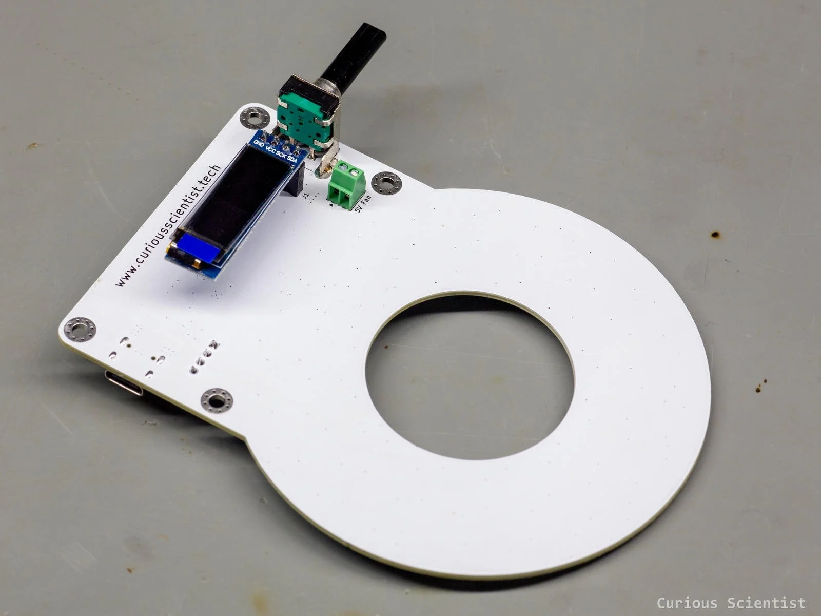
I also copied the rotary encoder and its pull-up resistors and capacitors from the power supply project. This is not that critical part; it is just worth mentioning, especially because I used a right-angle encoder instead of a vertical one.
The use of RGB LEDs is also something that I borrowed from an earlier project in some sense. Some time ago, I introduced a library for CH32 microcontrollers that uses SPI to create carefully timed pulses to drive a bunch of WS2812B LEDs. I adapted that approach in this design, so I use the chip’s SPI hardware to drive all 48 RGB LEDs.
Then, I had to implement some “new” circuits in the build as well. So first, let me tell you the motivation for it.
The LEDs require 5 V to operate. I can easily get 5 V directly from any USB adapter, so it should not be a problem, right? Well, the board has 48 LEDs, and each LED is supposed to draw 60 mA at full brightness when all three colour channels are active (i.e. the emitted light is white). 48×60 mA = 2880 mA, which is really close to what the USB can provide at 5 V. The maximum current for USB power delivery at 5 V is 3 A. So, we have 120 mA to spare, and we did not consider losses, the consumption of the microcontroller and the OLED display, and I always want to have a 15- 20% margin. So, obviously, 5 V won’t work.
However, at 9 V, a power-delivery-capable adapter can supply 3 A as well. But now, instead of 15 W, we have 27 W; much better.
So, I decided to request 9 V from the USB power adapter and then convert it to 5 V locally. This actually happens twice, using two different principles, and I'll tell you why.
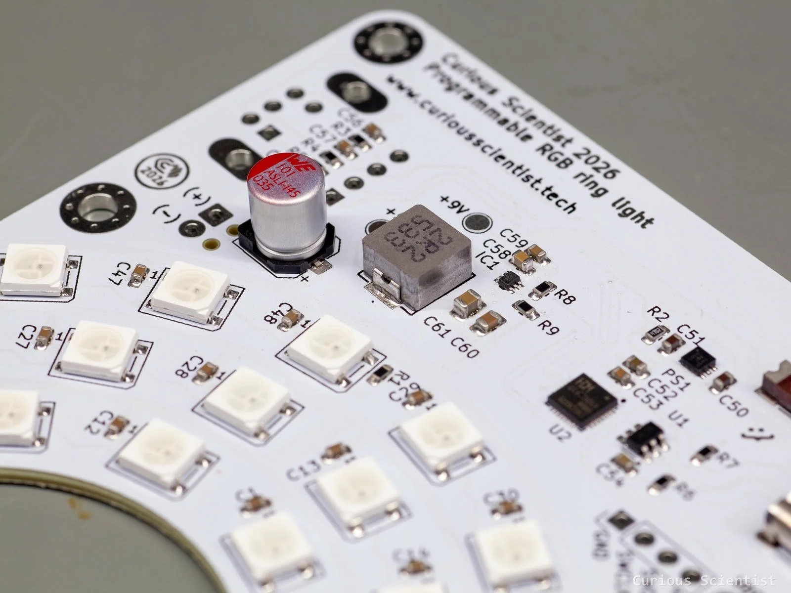
First, a TPS7A2550 low-dropout regulator converts the VBUS voltage to 5 V. This LDO is used to provide power for the microcontroller, the OLED display and the rotary encoder. When the circuit is powered up for the first time, it receives 5 V through the USB. Since the LDO is a fixed 5 V regulator, it has no headroom to regulate to 5 V; therefore, the initial voltage on the “logic 5 V net” will be somewhere around 4.9 V. This is not a problem for the components; they could operate at 3.3 V without an issue. But I did not want to settle for a 3.3 V logic voltage net, because the LEDs require 5 V driving signal. So, I used a different approach.
Once the microcontroller is up and running, it negotiates 9 V from the power adapter. This is the fun part. The LDO now works as it should; it regulates the 9 V to 5 V, and the next power-related part comes into the picture.
The circuit board also contains a buck converter based on the TPS564242 chip. This chip is capable of delivering up to 4 A, which gives us enough headroom at 5 V. The converter does not work immediately, but it is enabled by the microcontroller via software. The buck converter is only enabled when the 9 V negotiation is successful. So, initially, it is disabled, and when 9 V is present, the MCU turns the buck converter on.
All this happens within a second or two, so the user can’t really notice anything from the things happening behind the scenes.
Then, it is just business as usual: the user can control the LEDs either via USB or the onboard display and rotary encoder.
Board design
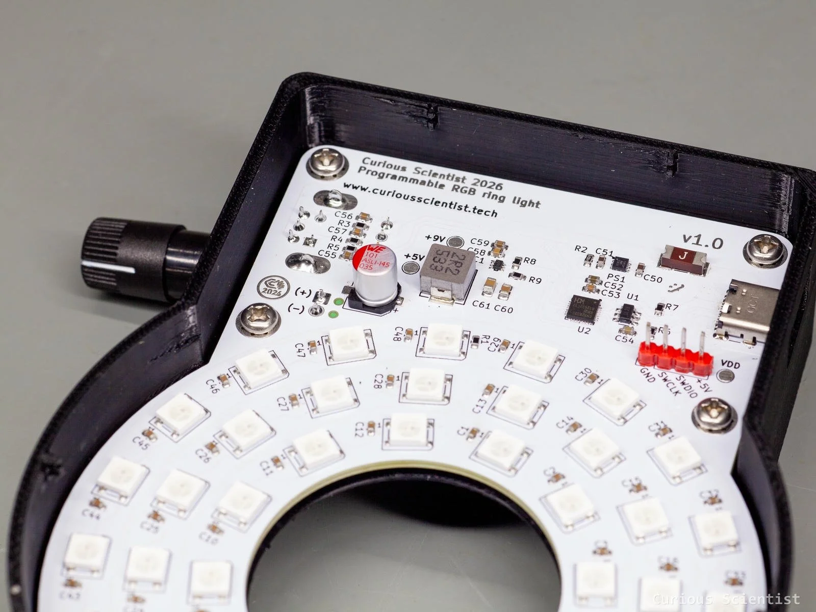
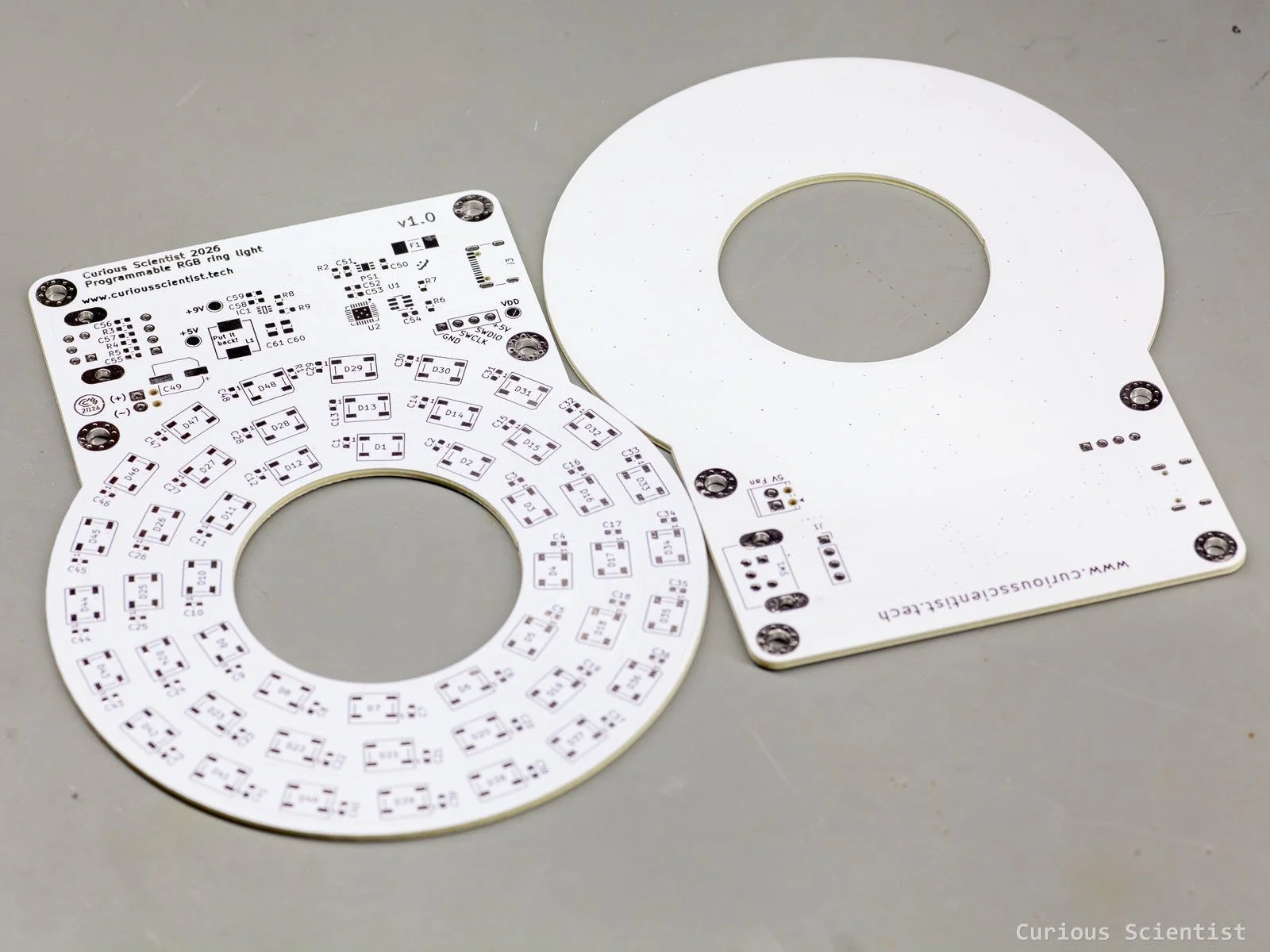
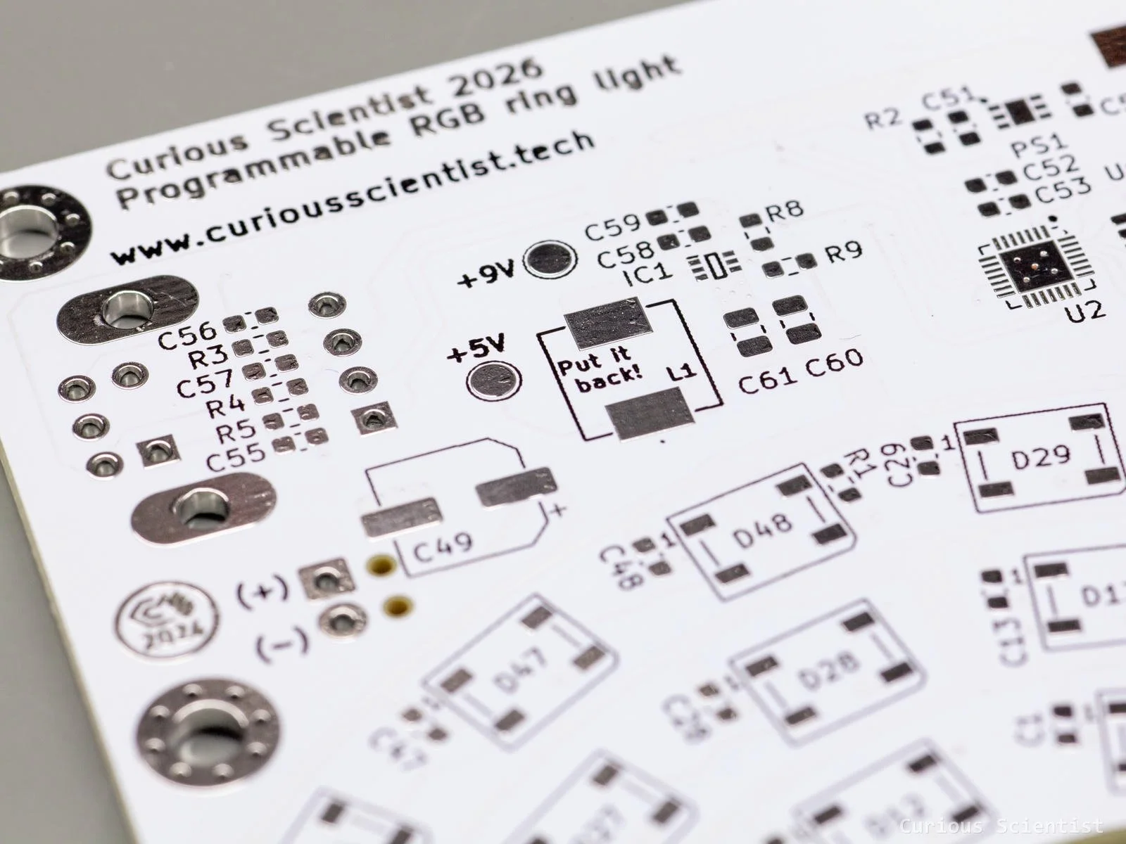
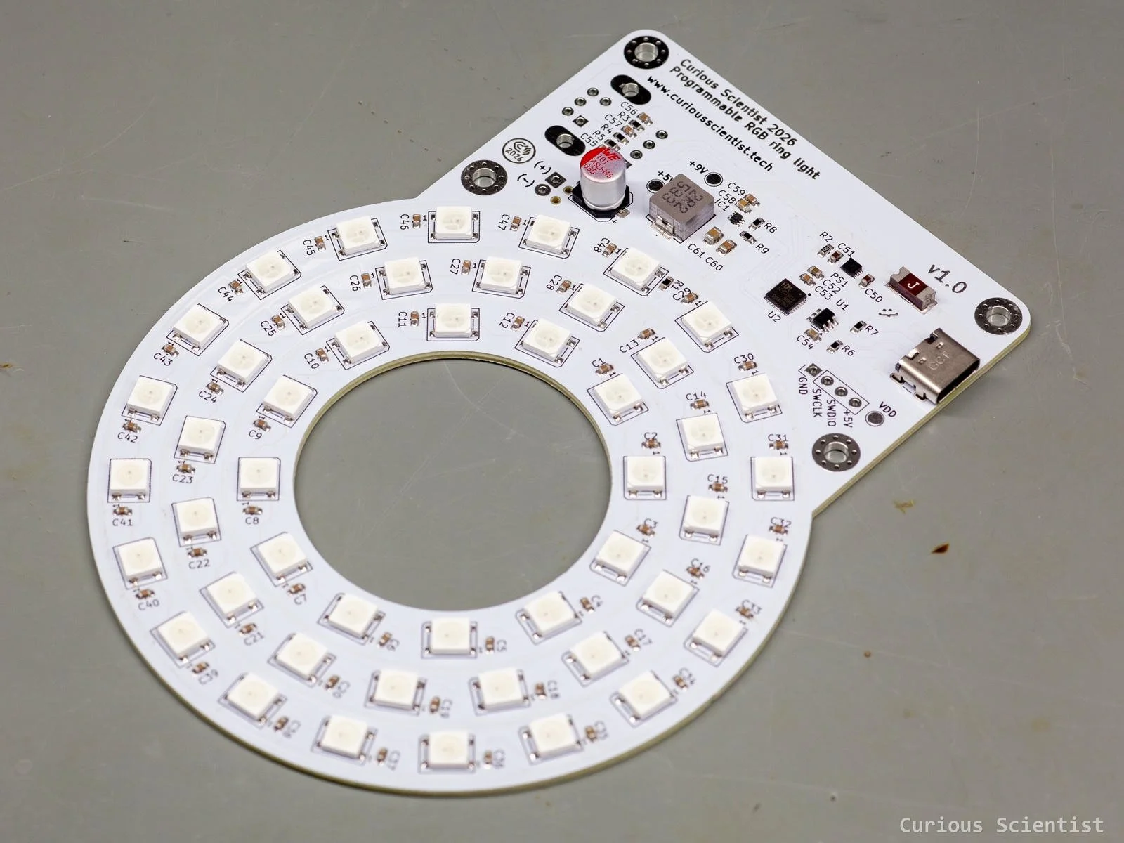
The board design was mainly governed by the fact that the final product is going to be a ring light. So, obviously, it should be ring-shaped. I took the measurements of my old ring light and eyeballed the dimensions of this board based on it. The inner diameter of the PCB, the “peek hole”, is 42 mm, and the outer diameter, or width, is about 96 mm. I chopped the upper part of the ring and added a rectangular section to it to accommodate the microcontroller, the power supply and other parts of the circuit. From a feasibility perspective, yes, I could have just kept the ring and designed the board around the shape. But, since I assemble these boards manually, I did not want to suffer with the soldering. So, I just made the board larger.
The PCB layout is not strange in any way. I just followed the usual practices and guidelines that I’ve already been following in my earlier designs.
The USB line is routed as a differential pair, and the D+ and D- lines are equipped with ESD protection
The MCU and the peripherals are fed with 5 V from a modern LDO, and decoupling capacitors were used where it was required
The programming pins and power pins for the MCU were broken out to allow programming and debugging
The VBUS line is converted to 5 V for the LEDs with a modern buck converter
The rotary encoder pins use pull-up resistors and capacitors for filtering
The rectangular part received four padded M3 mounting holes
The powering of the LEDs is one of the interesting things on the board worth mentioning. First, I added an electrolytic capacitor to this line to avoid voltage dips when the brightness suddenly changes. Then, I also routed 2 mm-wide traces to the main distribution points of the LED supply line. The LEDs are arranged in 3 concentric rings, and their supply lines are arranged similarly. I drew a 1 mm-wide ring for each LED ring as a supply line. These supply rings are connected together and to the output of the buck converter by the previously mentioned 2 mm traces. This should provide enough copper to avoid excessive temperatures and potential voltage drops. Since the whole bottom layer of the board is poured with the ground layer, the ground can be accessed by vias.
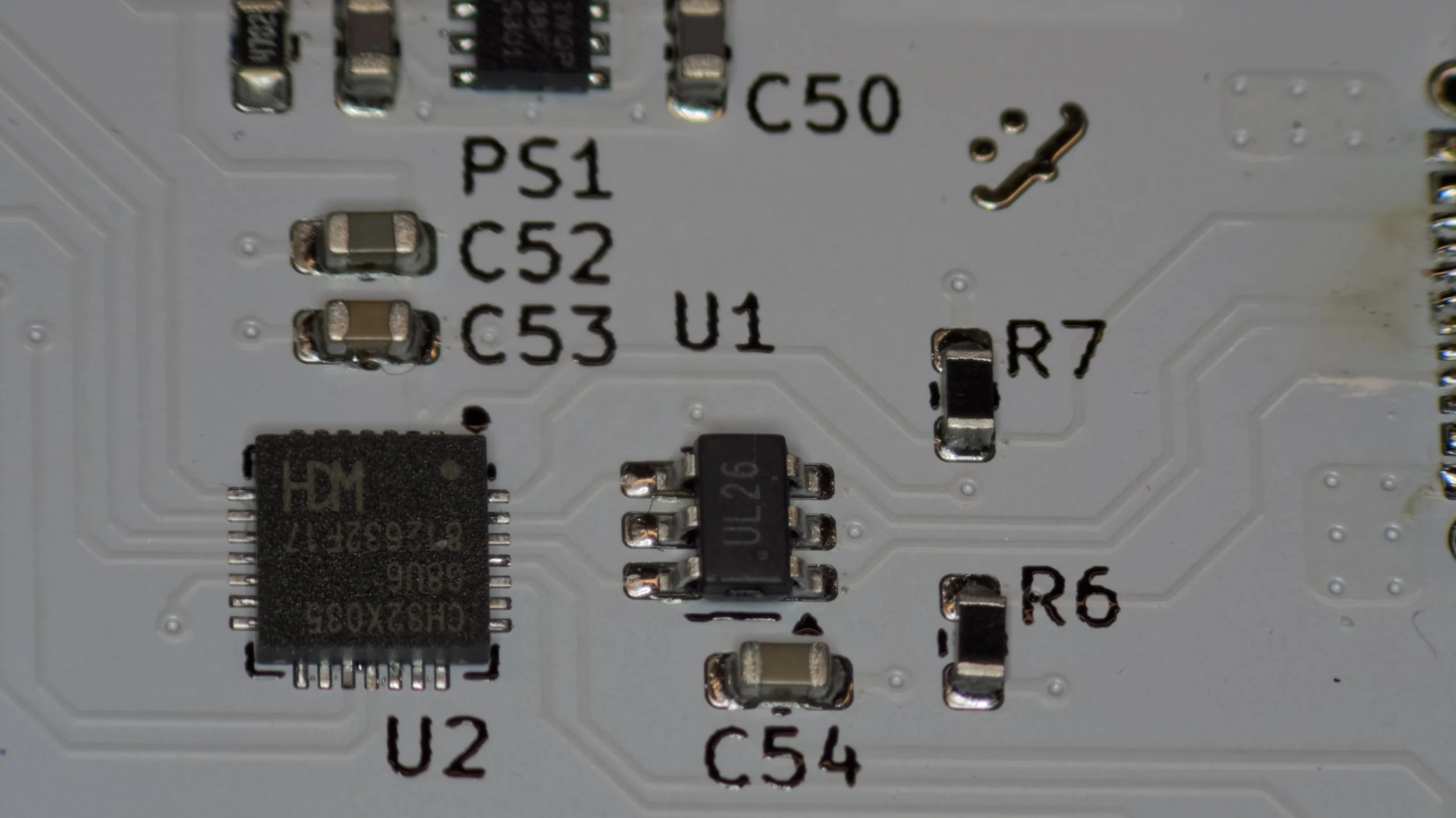
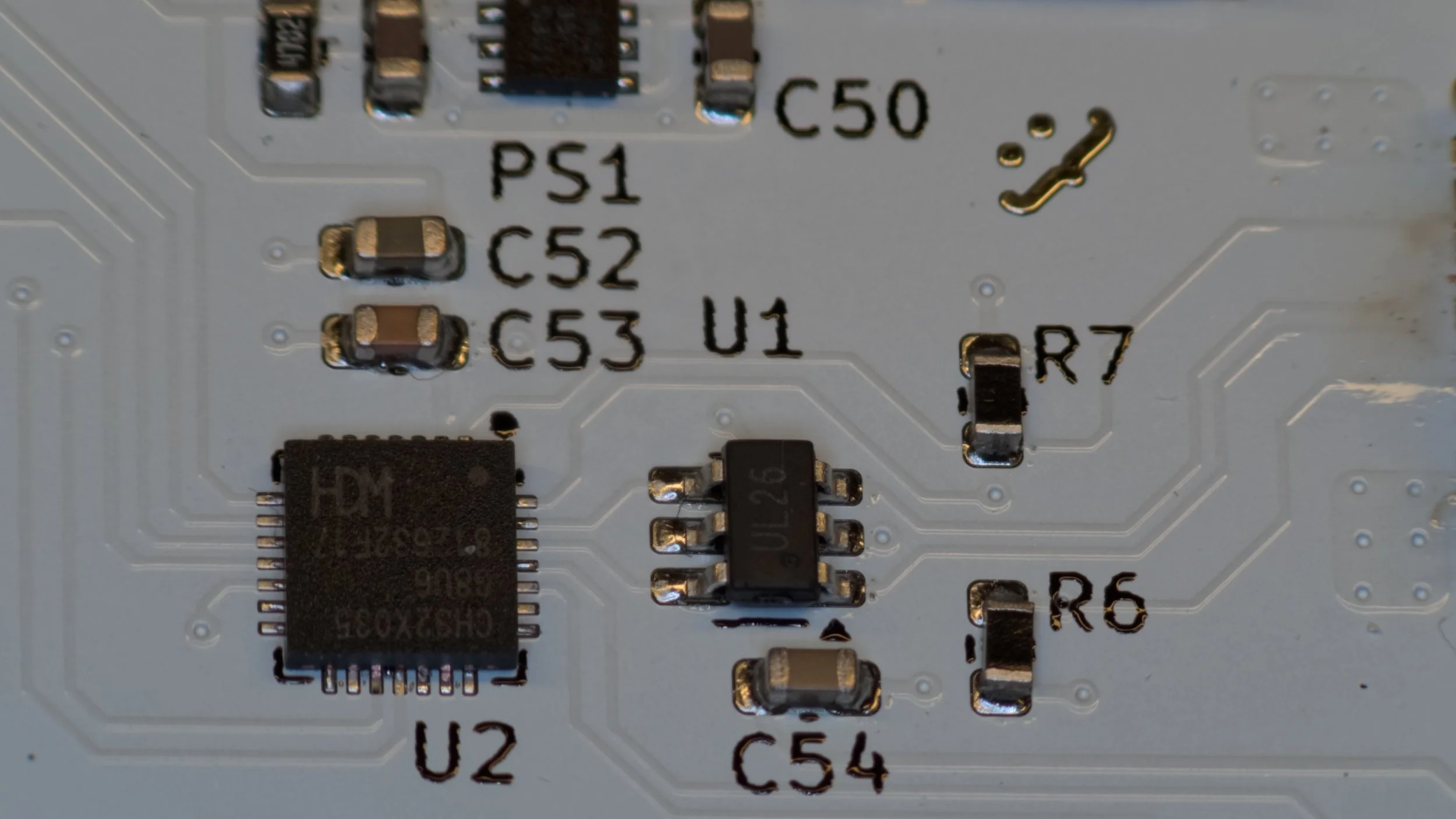
One interesting thing that I want to mention is related to the fact that I ordered a board with a white solder mask colour. Not all colours are the same from a production perspective, and while the green solder mask is more forgiving and flexible, the white needs a bit more attention. When I placed the first order with PCBWay, my design was rejected, and they carefully explained why. Not only with text, but with pictures as well! So, the white board does not like the default WQFN-28 footprint dimensions of the microcontroller. The original footprint has 0.2 mm-wide pads, and consequently the distance between the edges of two adjacent pads is also 0.2 mm. This would be OK with a green PCB, but not with a white. PCBWay carefully explained that they would need a 0.22 mm distance between the pad edges to avoid solder bridging.
I was offered three options:
Change the colour to green (too easy, and I specifically wanted a white board for this application)
Leave it empty without solder mask (might be “ugly”)
Extend the distance of the pads to at least 0.2 mm (this sounded the most straightforward)
So, I went into the footprint editor in KiCad and decreased the pad width for all the pins to 0.18 mm. This increased the pad-to-pad distance to at least 0.22 mm. But this was not enough. I also had to change the cutout size for the stencils by repeating the same steps on the F.Paste layer. This ensures that I do not apply excessive amounts of paste on the shrunk pads. Furthermore, I also had to decrease all traces to 0.18 mm wide because if I kept the original 0.2 mm all the way to the pads, then I’d have the same issue. PCBWay can go all the way down to 0.1 mm with their regular boards, so 0.18 mm is not at all an issue here.
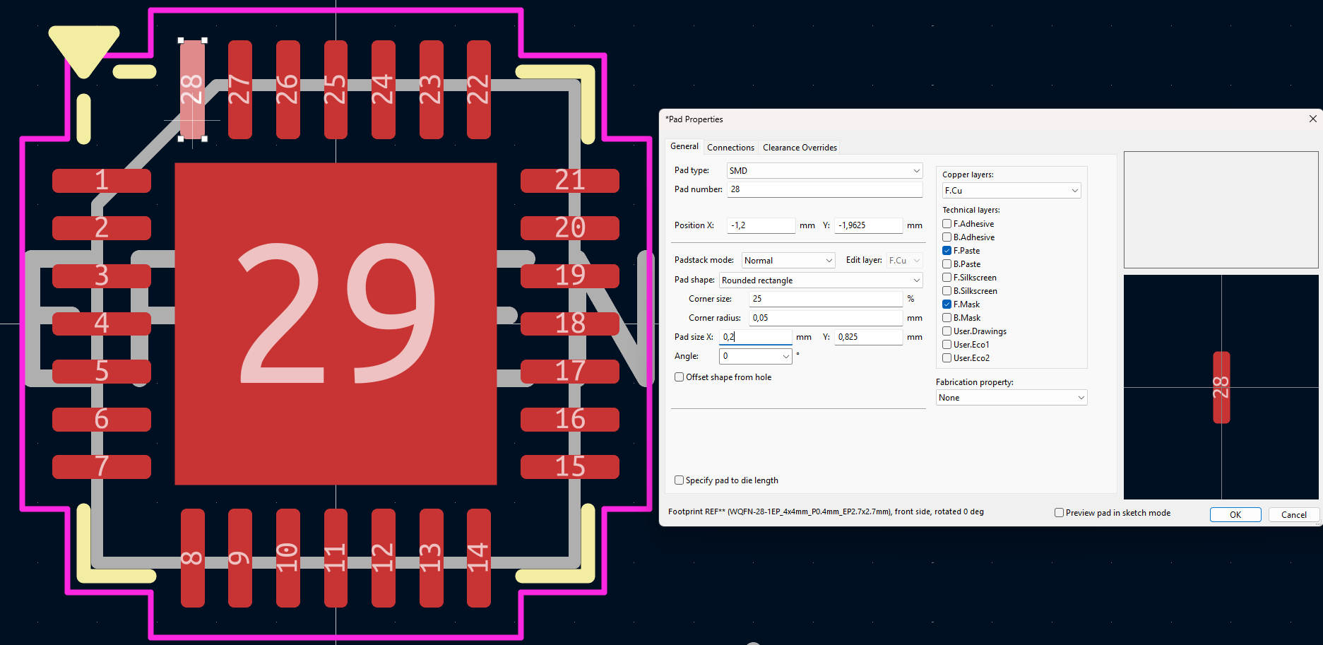
Problematic footprint with 0.2 mm pad width
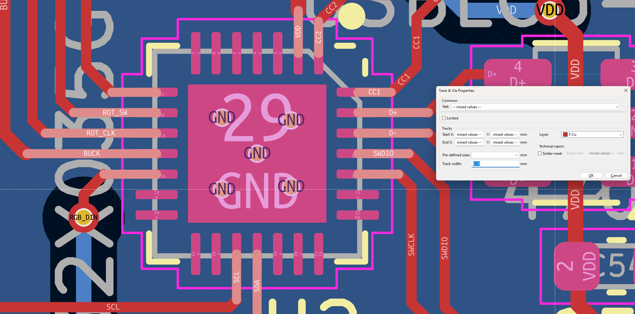
Also the width of the traces had to be decreased to 0.18 mm
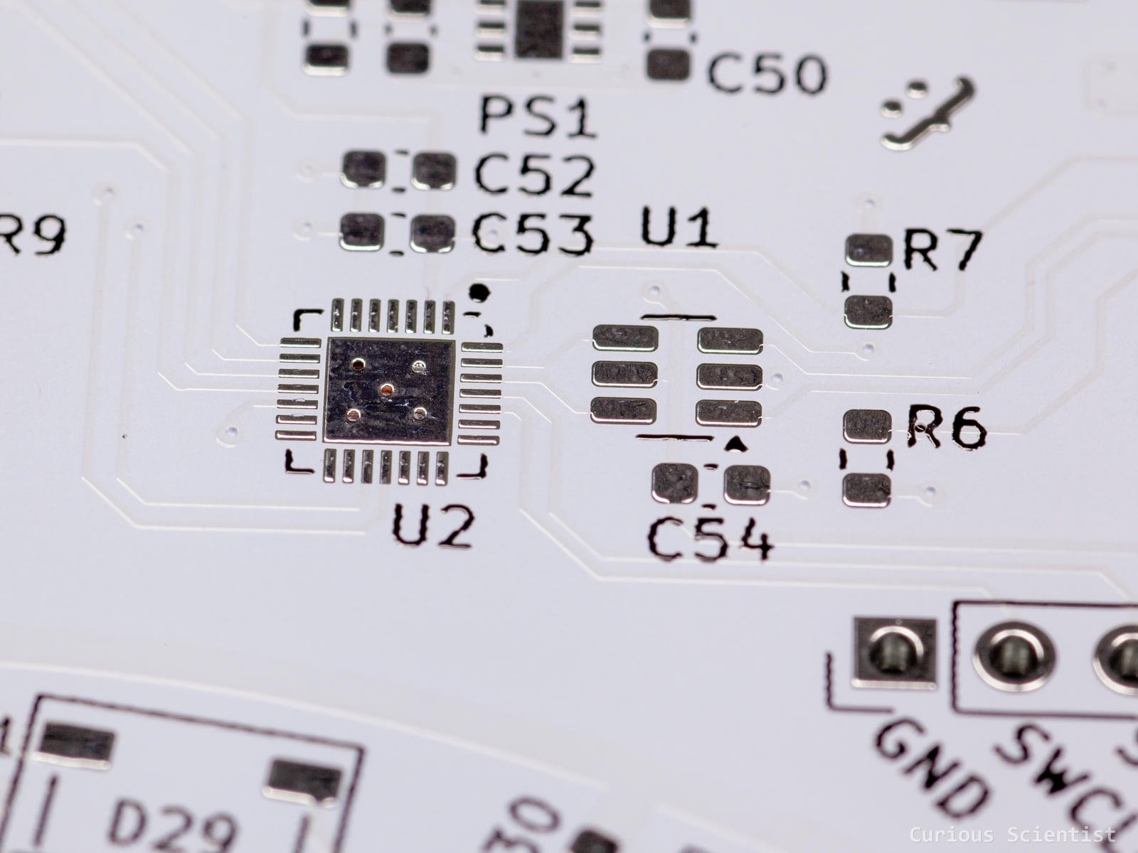
The fixed footprint (U2) with the 0.18 mm surrounding traces
Enclosure design
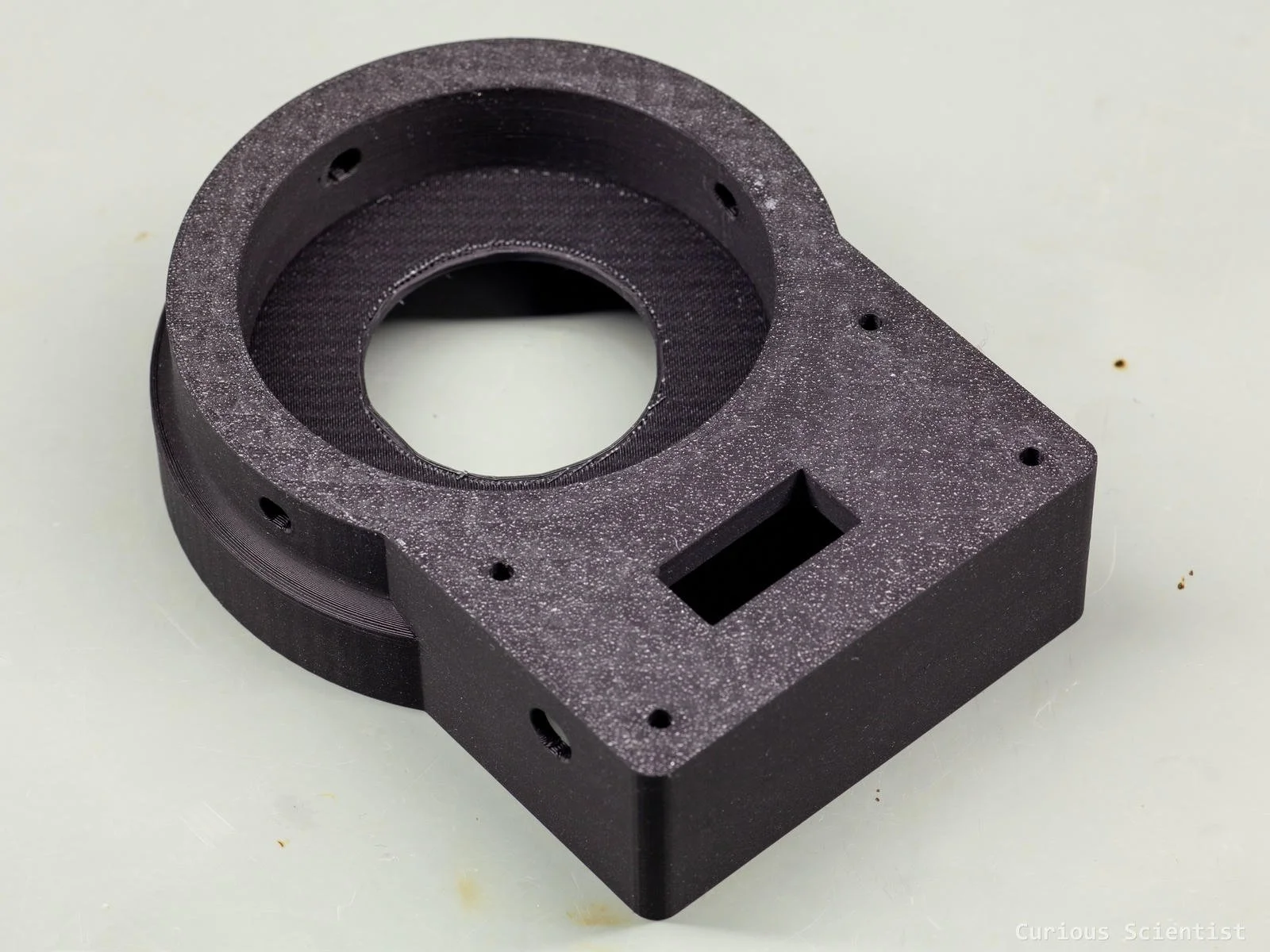
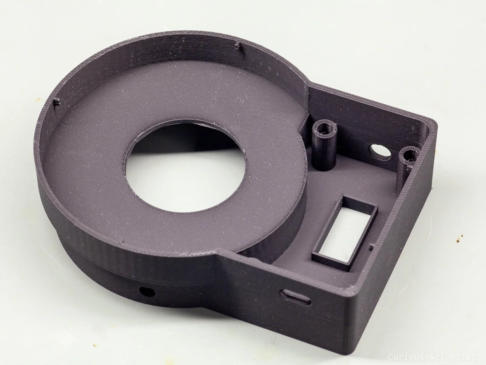
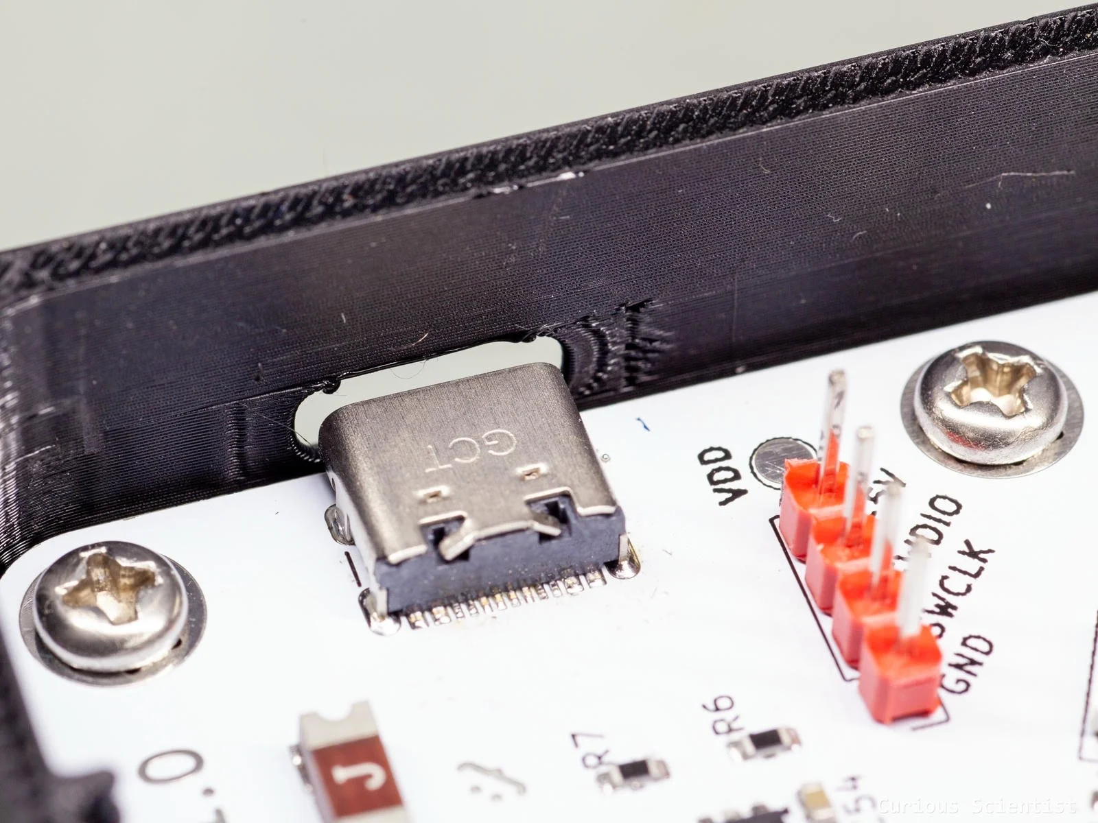
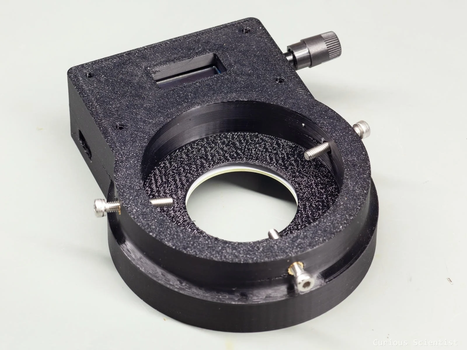
The enclosure consists of two parts: the protective shell and a diffuser. The protective shell surrounds the PCB, and it provides mounting points for the camera lens. There are holes in it for the USB-C connector and the shaft of the rotary encoder. There is also a window for the OLED display. I used four M3 insert nuts to fix the PCB in the enclosure. Further three M4 insert nuts were used to fix the full device to the lens using three set screws.
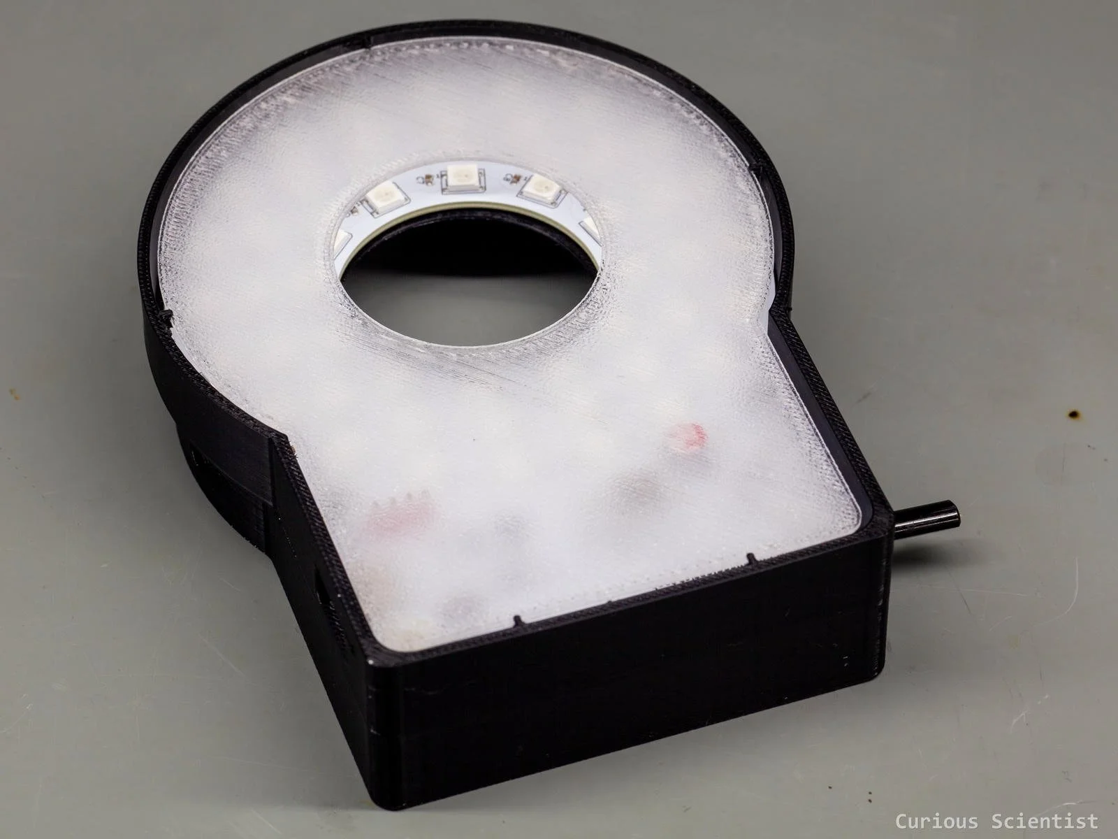
Along the edge of the front side of the enclosure, there are several small mounting points for the diffuser. To make a more homogeneous and, well, diffuse light, I decided to 3D print a thin translucent PETG sheet in the shape of the PCB. I tested some settings that were supposed to make my print more translucent, but something might have gone wrong because I did not get the desired result. But anyway, the diffuser turned out to be good. It clicks into the mounting points well, and it stays in place. And the most important thing is that it makes the LEDs’ light much smoother and more homogeneous. Finally, it makes the design look cool because it exposes the whole circuitry on the PCB. However, in the future, I will keep experimenting with different slicer settings and thicknesses to make the diffuser better.
Software
The firmware I developed for the CH32X035G8U6 microcontroller does the following:
USB-PD power negotiation
Rotary encoder handling
OLED display driving
WS2812B driving via SPI (!) and DMA
Buck converter control (enable/disable)
The most interesting part is, of course, the LED control. I implemented the following things. I created 8 different pre-programmed patterns that the user can control independently: all 48 LEDs at once, inner, middle and outer ring, four sectors, a.k.a. quadrants. These patterns can cast different shadows and provide different visual effects for the observed scenery.
All these patterns can be controlled in terms of brightness and colour. The colour can be adjusted according to some preset colours like white, red, green and blue, or, if the user wants to customise the colours more, independent R, G and B values, or hue and saturation values can be adjusted as well. We can even mix the patterns by, for example, enabling the inner ring and the upper-right sector of the LED array.
The settings are only stored in the RAM because I did not bother implementing a save option. It is very quick to adjust the lights, so I did not feel like putting effort into this part.
Test results
I tested the LED light in several different scenarios, just to make sure it performs at least as well as my old ring light. The old ring light is smaller and more compact; however, it only has white LEDs, so it is directly connected to a power source through a simple dimmer circuit, and that’s all. No RGB, no custom lighting pattern, nothing. At maximum brightness, it consumes around 1.2 A at 5 V, so about 6 Watts. The only advantage of this light I noticed so far is that it has a built-in polariser, which can result in better image quality sometimes. This is mainly due to how reflections behave when a polarising filter is used.
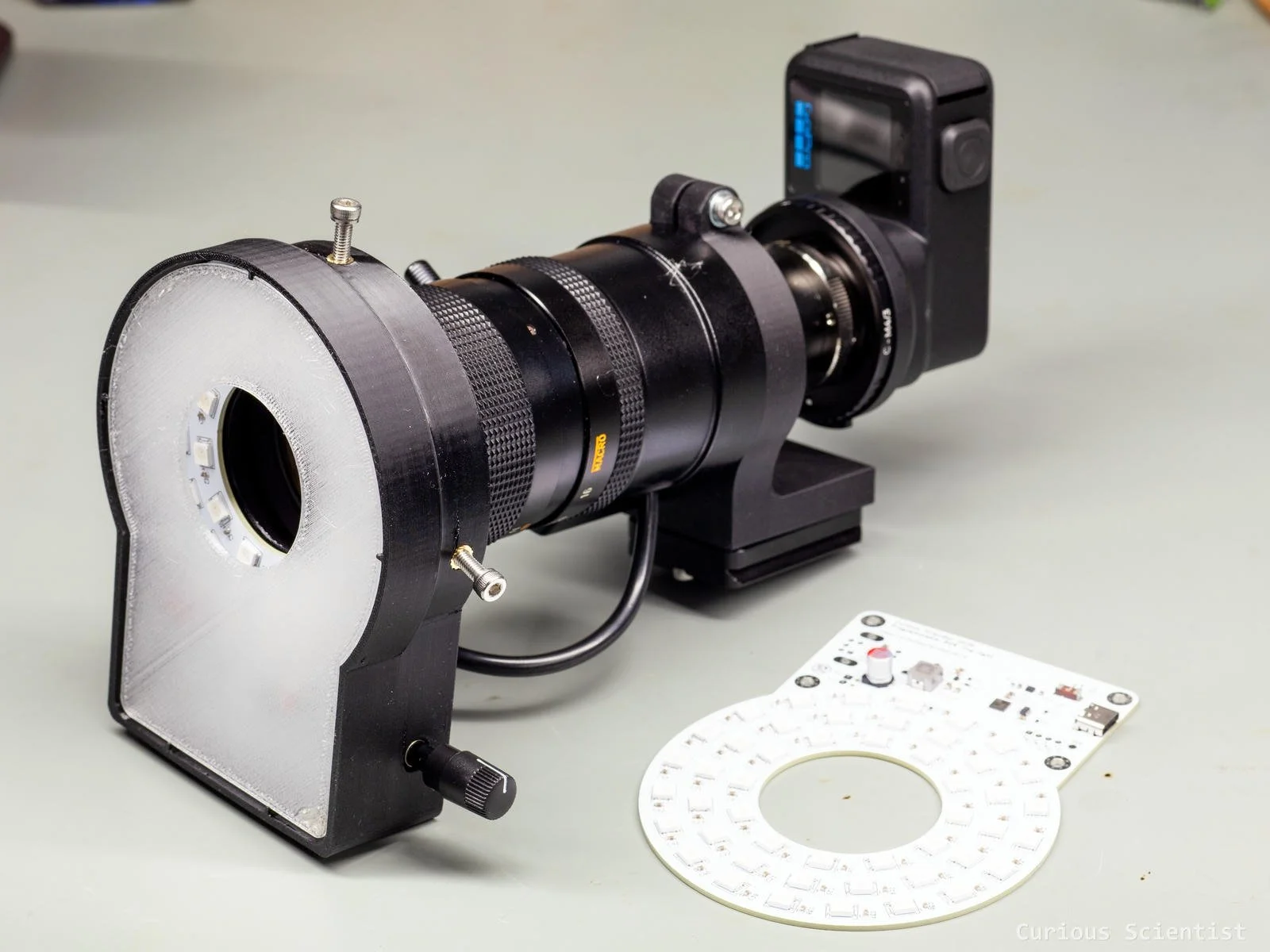
The camera test setup is simple. I used the new GoPro Mission 1 Pro ILS camera with a C-mount adapter, a 2x extender, a 20 mm extension tube and a Canon 16-100 C-mount zoom lens. It is a great optical setup I’ve been using for a very long time with my other camera, the Hawkeye Firefly Split V6 PRO.
Then, I mounted the whole thing, and I put a PCB under the camera. Coincidentally, another PCB of the same circuit I present in this article. I compared the unlit picture with the picture when the light is on at full brightness, or at other settings. I fixed the aperture on the lens, and I fixed the shutter speed on the camera, so the only variable is the ISO. When the ISO is low, better, less noisy footage is expected.
I tested the effect of the light by individually turning on the inner, the middle and the outer rings to see if there is any difference in the amount of light (ISO) or in the shadows cast by the different incident angles (although the diffuser should smooth the differences to some extent). I also tried to light up the different sectors individually, at maximum brightness, to see if it caused differences, but again, the diffuser did a good job. Then, I tried the different colours to see their effect. This was especially interesting with the white PCB that acted as a canvas for the different colours.
The difference between this light and my previous light is not very large. The previous light results in a bit better illumination, which drops the ISO value by roughly 10 units, from 10x to 9x. But this is not too much, and tuning the texture of the diffuser could improve the light of my ring light; I am pretty sure that I could achieve the same results. So, I don’t really lose any light with the new setup, at least not a very noticeable amount.
Enclosures with and without the diffuser
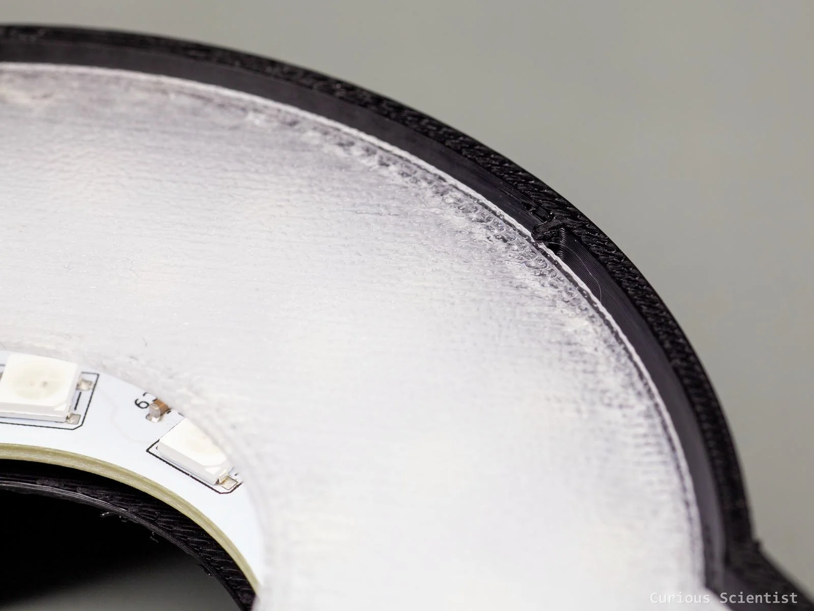
Tiny holder for the diffuser sheet
Additional resources
Get the PCB from PCBWay!

If you found this content useful, please consider joining my YouTube channel’s membership or leaving a donation.
Also, please consider using my affiliate links when buying relevant gadgets.