Customising my Hawkeye Firefly Split V6 PRO camera
In this article, I show you how I customised my previously introduced FPV camera. Despite the fact that the camera is advertised as an FPV camera, it has a much greater potential due to its unusually large, 1-inch type sensor. For my applications, I want to have the camera in a compact housing, and I want it to be portable, so if I want to record something outside, I should be able to use it as smoothly as possible. I will use the camera mainly for shooting macro videos of PCB assembly and recording footage using my metallurgical microscope. However, the camera is also suitable for recording high-quality footage outdoors as well.
Introduction
So, the whole story starts from when I ripped the thread of the original C-mount shell that came with the camera. It is just a plastic shell, and it was relatively easy to accidentally misalign the threads and break the plastic threads of the shell.
So, first, I tried to print an enclosure that has a 1-inch thread (1” x 32TPI) in it. It turned out surprisingly well, but the problem was still there: the thread is made of plastic. Then, I browsed the internet and I found a webshop in the UK that sold C-mount flanges. I managed to buy the absolutely last one from their stock, and they still haven’t restocked it since then. This is an issue because people cannot recreate my design. I searched literally for days, but it was impossible to find a proper C-mount flange.
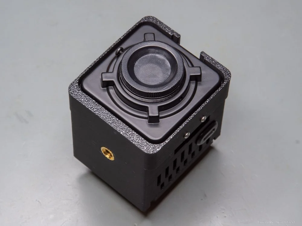
Then, I finally found the solution: a CCTV camera housing. It comes with a rotatable C-mount flange, a metal enclosure and some extra accessories. The good thing about the adjustable flange is that we can rotate the whole thread so that the focusing and aperture rings are facing us. Plus, the whole thing is about 4 times cheaper than the C-mount flange I found on the earlier-mentioned webshop in the UK.
I could have squeezed everything inside the metal housing, but I found it a bit cumbersome, because then I had to cut holes in the metal shell to access the HDMI, USB-C and SD card slots. So I printed a whole new enclosure around the front panel of the CCTV camera housing.
First, I had to design a holder for the sensor and the IR filter. So, first, I modelled the front panel of the CCTV camera housing, and then I started to draw a holder. I had to be careful to make the dimensions good enough, so the distance of the sensor is more or less (rather less) within the flange focal distance of a C-mount lens, which is 17.526 mm. If I make the sensor sit further than this distance, I will never be able to focus at infinity. If I make the sensor sit a bit closer, I will lose a little range of the focus, the focusing scale on the lens will be incorrect, and I can focus “beyond” infinity. This is a better problem than losing infinity. So, the holder is carefully designed to respect the flange focal distance. I also had to keep in mind that I need to put the IR sensor between the lens and the sensor, so I shaped the mount accordingly. Finally, the adapter is attached to the metal housing via four screws.
It took me 4 iterations to dial in the dimensions and make the print fit nicely, which is not too bad. I did not waste too much filament and time.


Enclosure
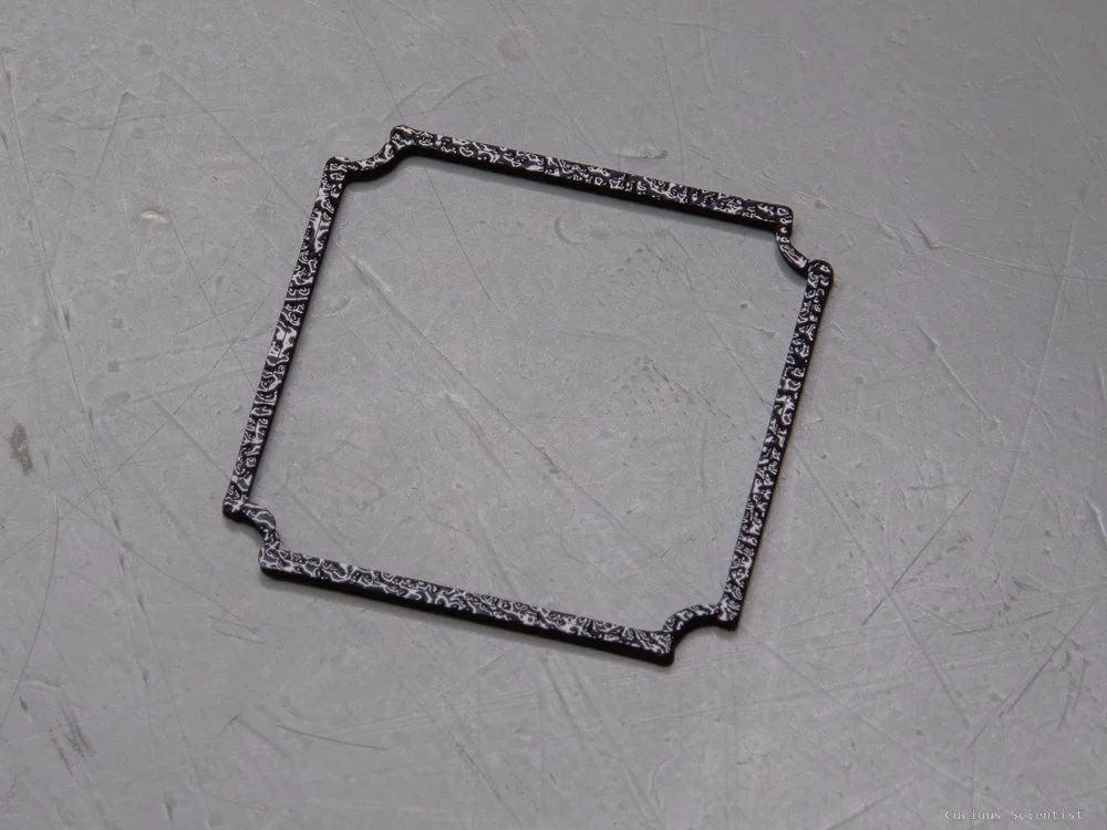
The next step was more difficult: I had to design a housing for the main module of the camera. I designed it “bottom-up”, meaning that I designed the housing as a continuation of the metal front panel that holds the lens and the sensor. However, I “cheated” a bit, and I made the metal front panel sunken into the plastic housing. The front panel has four little M3 threaded ears. I use them to attach the front panel to the plastic housing. The front panel also has some metal tabs which help support the plastic shell.
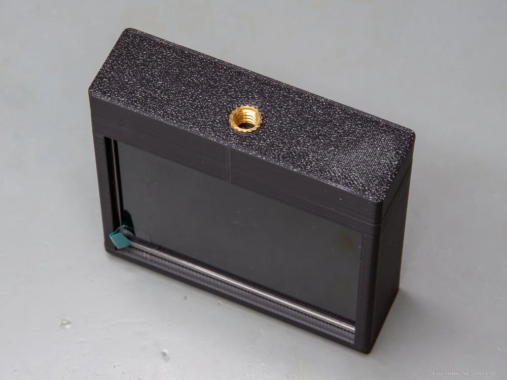
The metal front panel sits in the plastic housing, which is 50 mm x 50 mm, and its corners are 5 mm radius. The plastic housing is 54 mm (w) x 60 mm (h). I had to increase its area because the housing also has a cold shoe mount on the top and a 1/4” thread at the bottom, so we can attach a display and mount the whole thing on a tripod.
Inside the housing, there is a plate that accommodates the main module of the camera. I left a large hole in the centre because I wanted to allow airflow around the whole camera module, plus I needed some space for the cable between the module and the sensor board. I also shifted the camera module up by a few millimetres from the centre, so there is enough space for all wires. The remote wire comes out on the same side as the wires for the sensor, so I needed more space around that area.
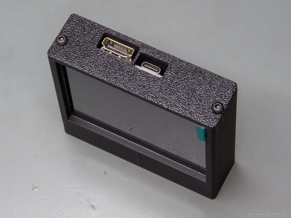
Then, I had to accommodate the slots for the micro-HDMI connector, the USB-C connectors and the SD card slot. Due to these exposed slots, the camera is not splashproof or dustproof. I also made a neat little trick for pressing the two buttons on the camera module.
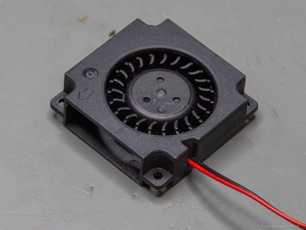
Above the connectors, there are little windows on the two sides of the plastic shell. They are about the same position as the heatsink attached to the chips on the camera module, so they hopefully help with the air circulation. Since the camera module can get as hot as 70°C according to my measurements, it is mandatory to have forced air cooling; otherwise, the plastic shell made of PLA might become too soft. If you print the enclosure from some other material, it might not be an issue, but I assume that most of the people (including me) use PLA for 3D printing. In addition to the forced air cooling, I removed the originally attached metal shell from the camera module and attached pure copper heatsinks to the two main chips on the module. Hopefully, this modification significantly improves the cooling.
The enclosure ends in a lid which is also sunken into the shell. This way, the device looks quite sleek and compact. The lid has a slot in it that accommodates my custom 5-way navigator I developed recently. This navigator was inspired by the remote of this device, and it is 100% compatible with the camera. So, I added to the camera as an improved remote control. The original remote is way too large, and it does not have any mounting holes, so it is a bit cumbersome to attach it to anything unless you want to glue it to the surface.
You might ask, Where’s the battery?
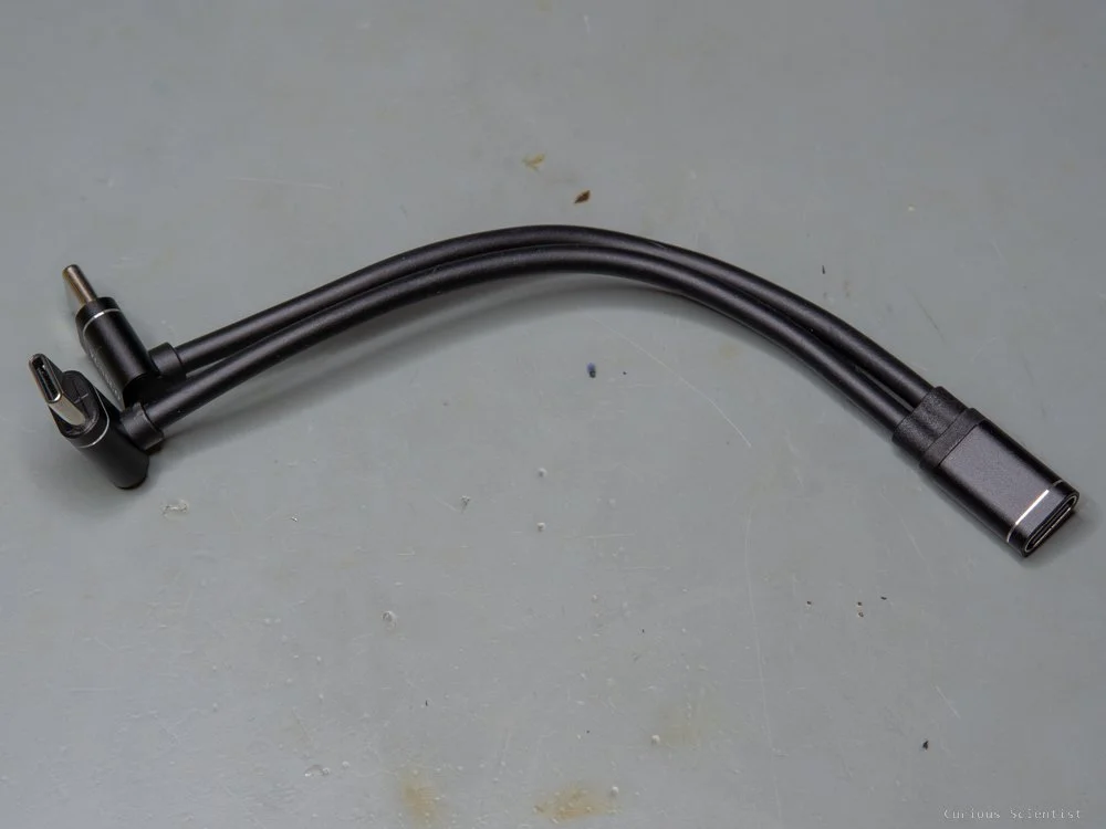
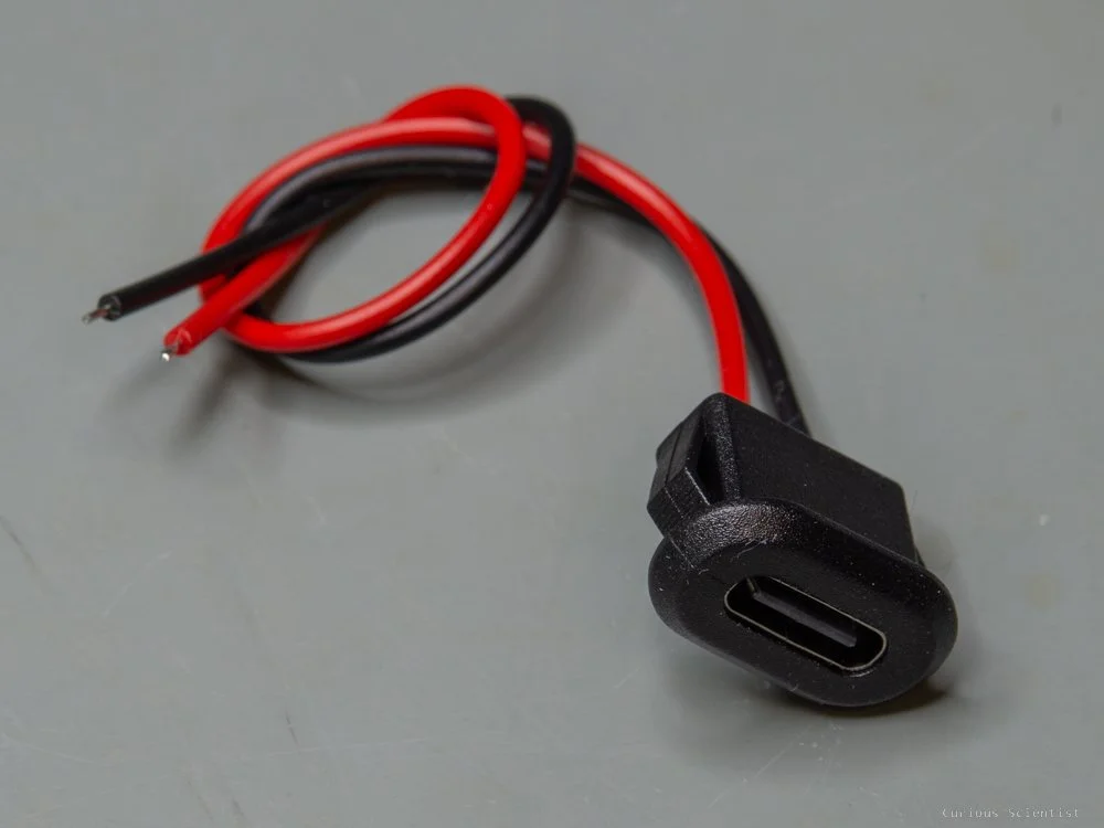
So, I decided to ditch the lithium battery via the 1S battery port for now. The battery I used (2000 mAh) dies rather fast, and it takes up a big space. Therefore, I decided to use an external power bank as a power supply. After a little searching on AliExpress, I found the perfect cable for this camera. It has a male USB-A connector, which is then split up into three male USB-C connectors. All three connectors can support power, and one of them can even be used for data transfer. So, it is a perfect cable because the data+power connector can be used for the camera module, in case I want to use it with a computer, and the other two can power the external display and the additional cooling fan. With this custom cabling, I can connect the camera module to whatever power source as long as it has a USB-A connector and it can source enough current. I am using it with a Deltaco PB-1065 power bank, and it works just fine. The power bank is an ideal choice because I do not need to struggle with different voltage levels and regulators…etc. This makes the project much more DIY friendly because fewer parts and modifications are needed.


External display
Now that the camera body is complete, we can attach a lens to it and power it up. But we cannot see what the camera sees because there is no display attached to it. There are two ways to solve this. A simple way is to add a cold shoe mount for phones and use a mobile phone as an external display. This is done by connecting the camera to the phone via WiFi. Actually, this is quite a comfortable solution because the camera’s app allows full control. So, in principle, one could ditch the controller on the rear panel of the camera and use the app to configure the settings of the camera and so on. The only “drawback” is the excessive battery use of the mobile phone when it is used as an external monitor. But since we have the 3-way USB-C splitter and the external power supply (power bank), this is not really an issue. We can charge the mobile from the power bank while it is used as an external monitor.
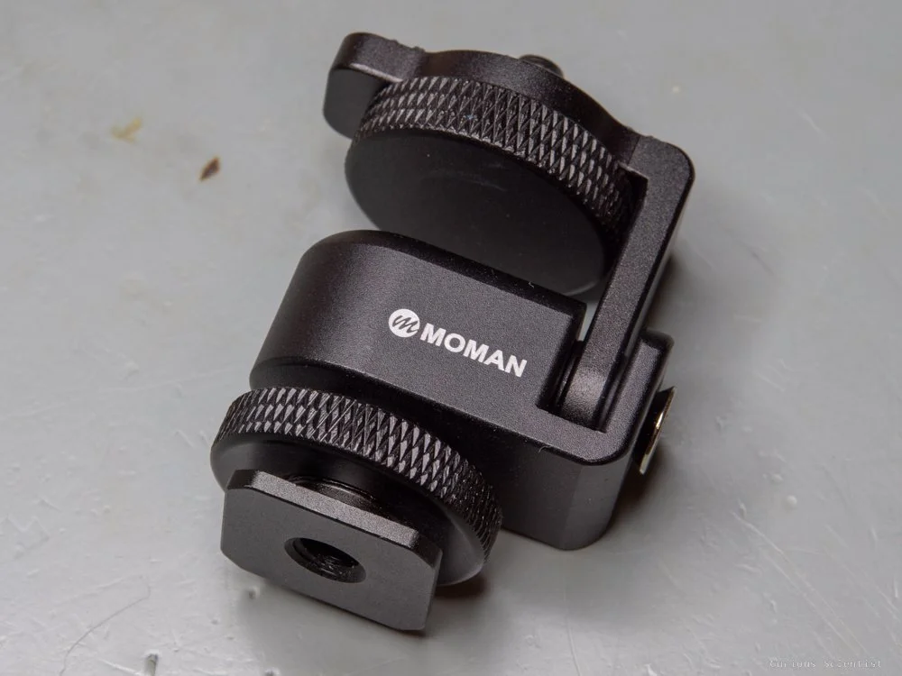
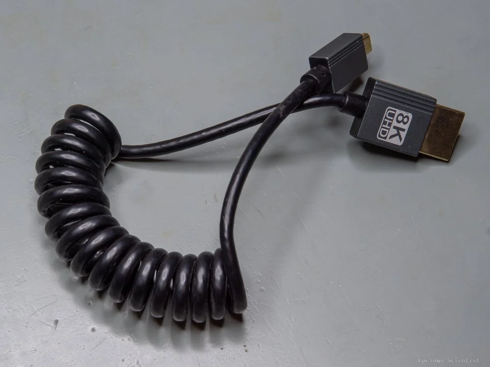
The other, perhaps more fun, option is to DIY an external monitor. I chose this way. I purchased a 3.5” HDMI monitor, and I designed a 3D-printable enclosure for it. The monitor consists of 2 components: the display and the driver board. The display is in a metal case, and the driver board is a circuit board that contains the video processing chip and the connectors. The video signal is transferred to the board via a regular HDMI connector, and the board is powered from a USB-C connector. So, we need a micro-HDMI-to-HDMI cable to display the camera’s output. The display is attached to the camera body by a cold shoe monitor mount. This specific mount allows for adjusting the angle of the monitor, which is nice. The only drawback of the monitor is that its aspect ratio is not the same as the camera’s aspect ratio, so the image shows up a bit compressed. But for me, this is not a big issue.


Extra accessories
Since the sensor has a really high resolution, it is worth discovering other lens options, too. However, it is worth noticing that nearly anything adapted to this C-mount camera will introduce a rather large crop factor, thus the field of view appearing on the camera will be quite narrow. I have a bunch of M42 lenses, so I purchased an M42-C-mount adapter, and out of curiosity, I also bought a Nikon F-C-mount adapter because I have a nice Nikon 50 mm f1.4 lens. The field of view is really narrow, but it is quite nice for “cinematic” shots.
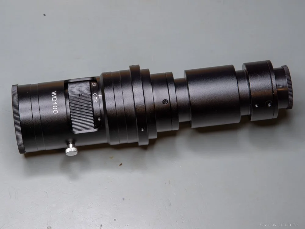
I also purchased an interesting microscope lens which has a fixed 100 mm working distance and an adjustable magnification. This lens is perfect for recording PCB assembly and soldering footage. But it makes the camera system quite large, so I have to use it carefully.


Additional resources
Get the relevant parts using my affiliate links:
Hawkeye Firefly Split V6 Pro camera
CCTV housing with C-mount flange
Become a channel member!