Subscriber count badge
In this article, I show you how I built a simple badge that fetches the number of subscribers from your YouTube channel and the number of followers from your Instagram account and displays them on an e-ink display. The device is based on an ESP32-C3 Super-mini microcontroller. It fetches the data via WiFi, it displays it on a 1.54-inch e-ink display, and it even keeps track of the battery’s voltage. The device sits in a 3D-printed enclosure, and thanks to the 2000 mAh LiPo battery and the TP4056 battery charger circuit, the device can sit on your desk without any cables, and it can operate for a few months before it must be charged again. I added a small loop to the enclosure, so you can even carry it around and show it off.
Components
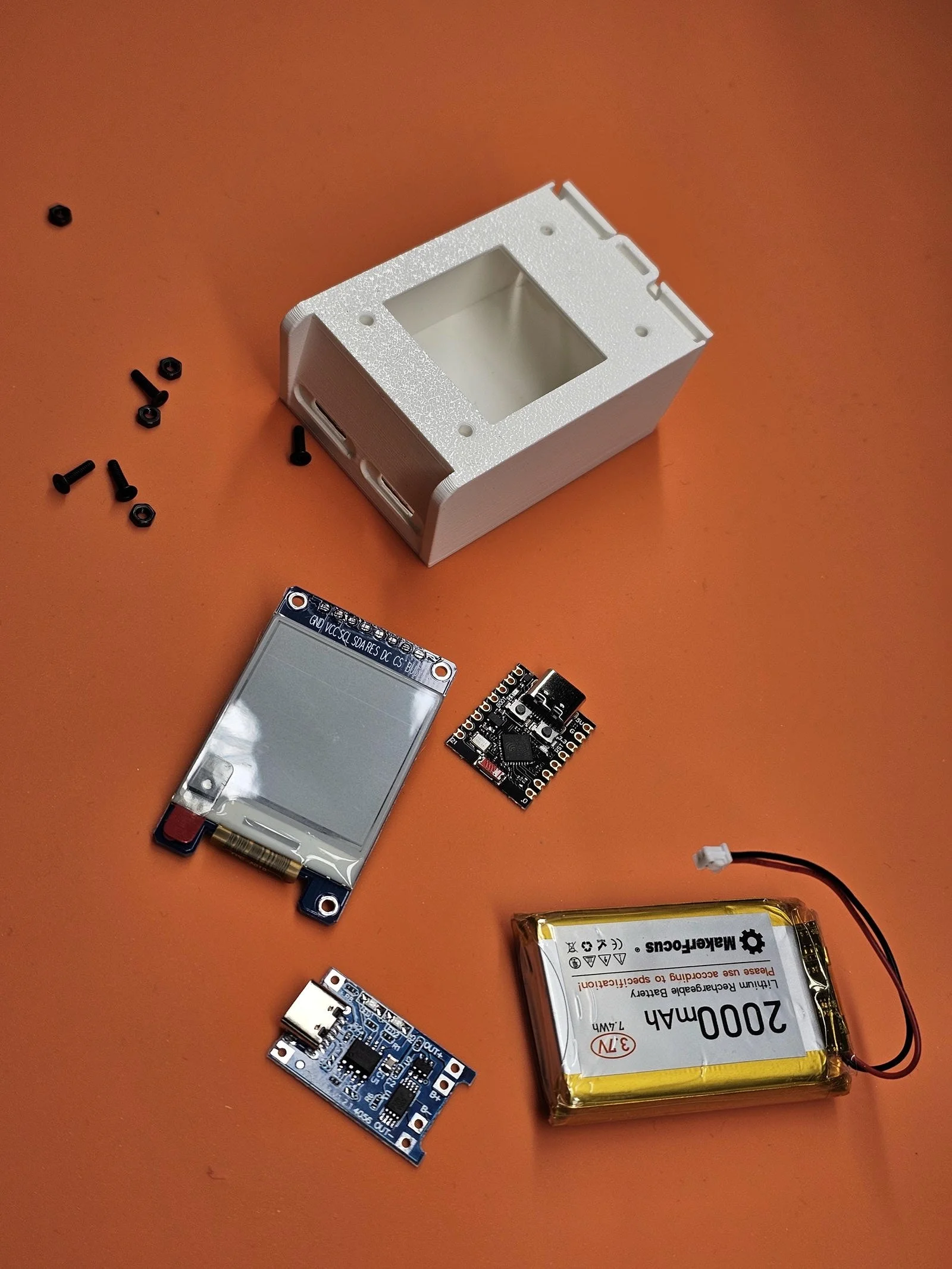
The device is based on the ESP32-C3 Super Mini microcontroller board. This is an amazing little board. I am not a big ESP32 fan, but this thing is probably one of the best microcontrollers for putting together small, internet-ready gadgets. It has WiFi, Bluetooth, a powerful CPU and enough GPIOs for connecting different peripherals to it.
I utilise the board’s WiFi to fetch the necessary details, and then I also use the SPI pins together with some GPIOs to send the information to the e-ink display. Furthermore, I also use an analogue pin that reads the output of a voltage divider that is monitoring the battery’s voltage level.
The e-ink display is a 1.54-inch 152×152 pixel display. It is driven by the SSD1680 chip. It is not that straightforward to use it with the typical Arduino display drivers, but I found the manufacturer’s example code that works perfectly, and it is easy to modify it for our own purposes. Just use the link above and download the GDEY0154D61LT Arduino Sample Code if you want to develop your own driver based on the manufacturer’s example code.
The 2000 mAh LiPo battery is managed and charged by a TP4056 module. This is a newer module because it has a USB-C connector. It can charge with up to 1 A of current, which allows us to quickly top up the battery.
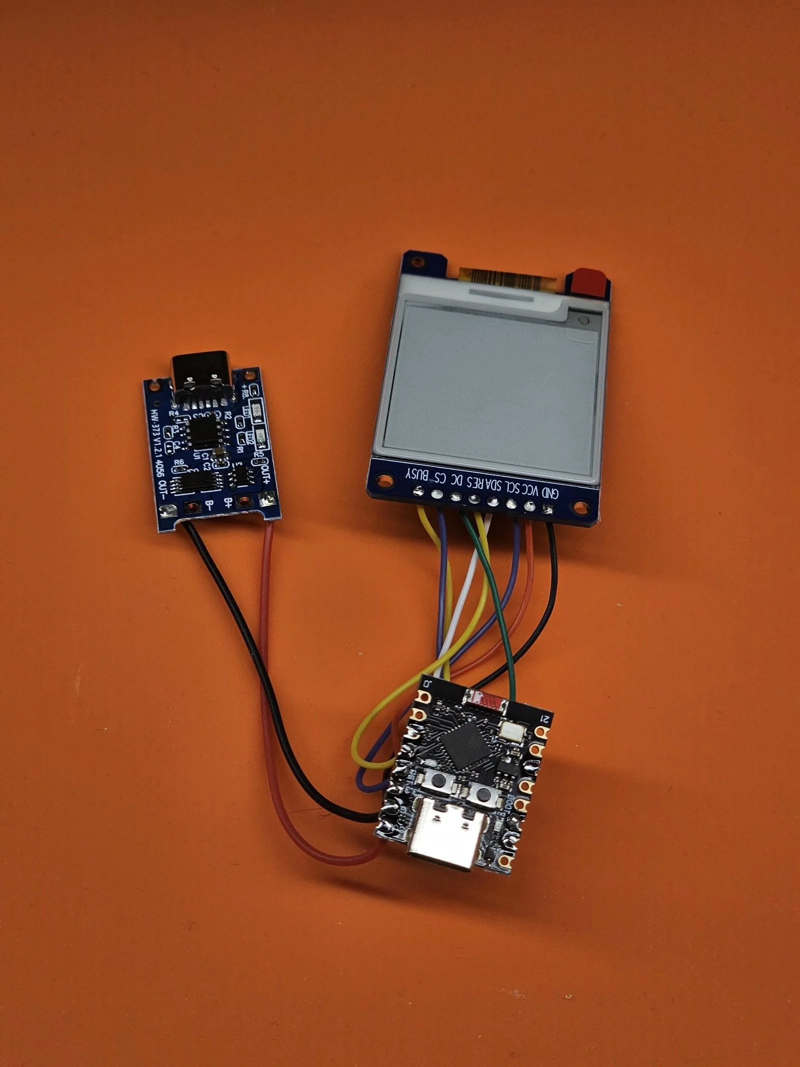
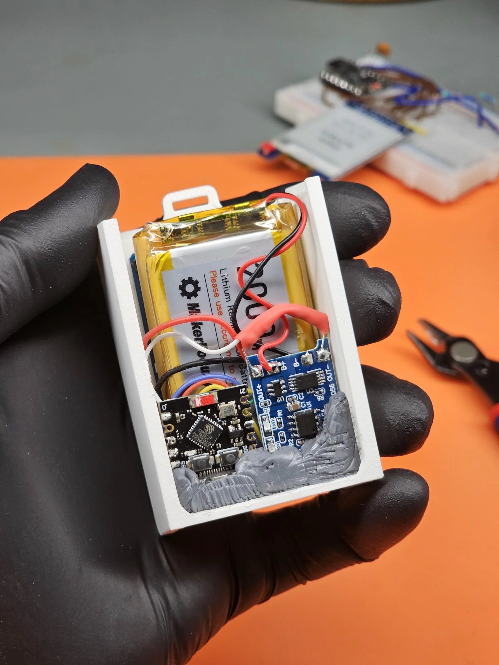
Everything is connected together via wires directly soldered into the circuits. Even the voltage divider for the battery monitoring circuit is just hanging in the air and soldered directly to the terminals on the PCB. As an extra safety step, I put a heat shrink tube around the resistors so the battery’s positive terminal does not accidentally get shorted to anything.
The display is directly screwed into the 3D-printed enclosure. Then, the two boards- the microcontroller and the charger circuit are fixed in the shell by using little supports in the 3D-printed shell and a good amount of epoxy putty. I started using more and more of this epoxy putty recently, and I really like it. It is easy to work with it and it provides a solid and strong bond. And a big plus is that I can shape it into whatever shape, so I can tuck it into tight corners and crevices to provide support and adhesion.

Implementation
The schematic is very simple. As I said, the e-ink display uses SPI. To further simplify things, it is a unidirectional SPI, so we only use the MOSI pin on the ESP32; we don’t need the MISO. So, MOSI, SCK and CS (SS) are the standard SPI pins on the microcontroller: GPIO6, GPIO4 and GPIO7, respectively. We also need to take care of the other three pins: BUSY, DC and RES, which are connected to GPIO10, GPIO2 and GPIO2, respectively.
Then, one more pin, GPIO0, is used as an ADC input to measure the output voltage of the voltage divider that halves the output voltage of the battery via two 470 kOhm resistors. I picked a relatively high resistor value to limit the current wasted by the voltage divider. It wastes around 4.5 uA continuously. I can live with that, considering that the project uses a 2000 mAh battery.
I experimented with the ESP32’s onboard LDO. It is marked as S2WL, and it seems to be an R1121N301B low-dropout voltage regulator. I manually fed the 5 V pin with an adjustable power supply and then gradually decreased the voltage while I monitored the 3.3 V line - the output of the voltage regulator. I could reach 3.6 V before I started to see the 3.3 V line decrease. So, I can drain the battery until it reaches 3.6 V. This is somewhat of an underutilization, but it is OK because, once again, I use a large-capacity battery.
But when I studied the power drain during sleep, I discovered something interesting. The board has a status LED that stays on during deep sleep, and it wastes a lot of power. So, I studied the available schematics on the internet, and I confirmed that the power LED is most probably directly connected to the 5 V rail, VSYS. The resistor, which is supposed to be 5.1 kOhm continuously draws roughly 600 uA. So, when I measured the sleep power, I could see around 650 uA with the resistor being part of the circuit.
So, after confirming the path of the LED with a multimeter, I decided to desolder the resistor to cut the power to the LED. Then I tested the power consumption during sleep by feeding the 5 V line through a multimeter, and I got a surprisingly low 106 uA power consumption. With an hourly wake-up pattern, this could be several months of battery life! Also, funnily enough, after cutting off the LED, I could not measure the sleep current consumption with the USB power meter anymore. It became so low that the device was not able to resolve it. Plus, the math- the estimated 600 uA current draw by the red LED was roughly OK as well.
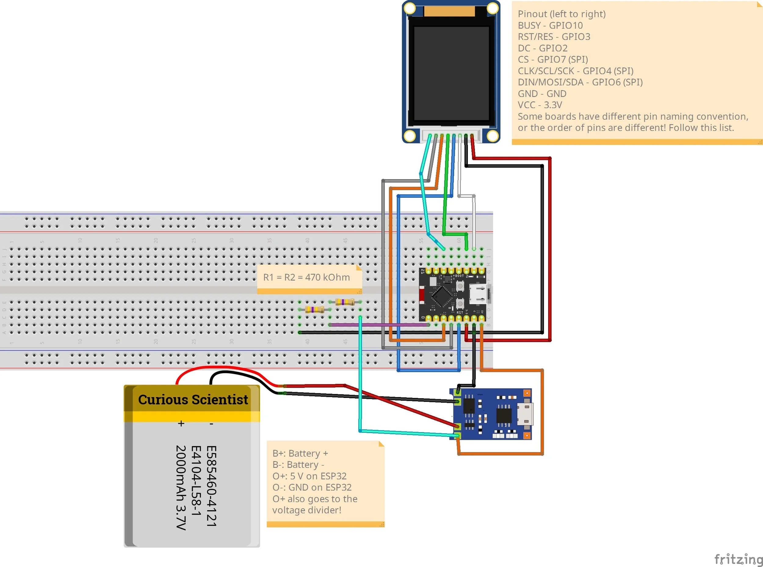
Fritzing sketch of the circuit. Keep in mind that the e-ink display might have different pin layout. Always follow the written list to make sure which pin on the display goes to a certain GPIO on the ESP32.
Coding and API access
The coding does not need too much explanation. If you want the full working code, please consider becoming a channel member, and you’ll get access to the Arduino code package.
The only thing you’ll need to fill in is the following:
Your WiFi SSID and password
Your YouTube channel API key and channel ID
Your Instagram token
The easiest is obviously the WiFi. Don’t forget that this gadget is portable due to the very good battery life. So, you can make a WiFi hotspot on your mobile phone and use it as the access point to the internet for the ESP32. Or, just use your home WiFi.
The YouTube channel API key and channel ID are a bit trickier, but not unsolvable. I just followed the instructions on this GitHub page.
The IG token is the most difficult. On the Meta for Developers website, we need to create an app. The use case is “Manage messaging & content on Instagram”.
Then, in the API setup with Instagram login, we need to generate access tokens. Here, we should add our professional or creator IG account. We should invite our account as an Instagram tester. To approve the invitation, open your IG app on your phone, click on the hamburger menu icon at the top-right corner, scroll down to App website permissions and accept the invitation. Then, generate the token and copy the whole thing using the copy button.
The rest of the stuff does not need to be modified, so just finish the app.
You can test if the token works with this URL by inserting your token:
https://graph.instagram.com/me?fields=followers_count&access_token=YOUR_ACCESS_TOKEN
Then, just add the token to the Arduino code and upload the compiled code to your ESP32.