(More than) Full-frame line scan camera
In this video, I show you my attempt at building a “full-frame compatible” line scan camera using the TCD1304 linear CCD. I have many projects based on this CCD, and I have actually tried to build a full-frame scan camera already as well. But this time, I drop the sophisticated mechanics from the camera, and instead, I focus more on software and data processing. Until I can come up with and assemble a proper mechanism to move the CCD to scan the image plane of a lens, I have the CCD fixed in the centre of the image plane and move either the object I want to capture or the camera.
Introduction and basics
I have really carefully described how the TCD1304 linear CCD works and how one can configure an STM32F401CCU6 microcontroller to drive it, and acquire its signal, so I am not going to repeat it here.
Plus, I made a breakout board and a standalone board for the TCD1304, so it can be used for different applications in an easy way.
However, I will focus more on the practical stuff around the line scan camera and its working principles.
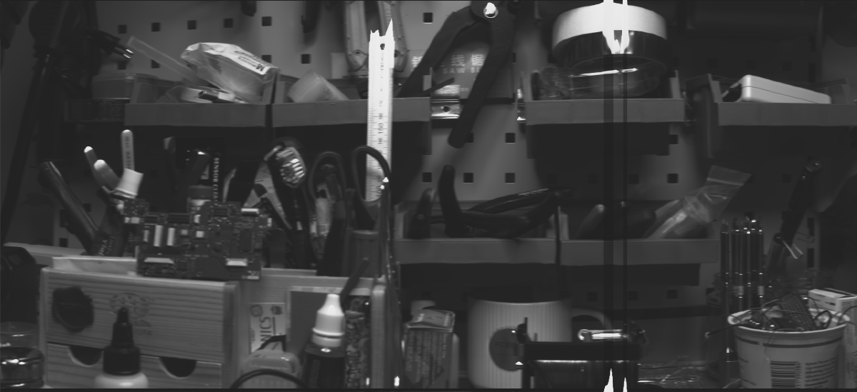
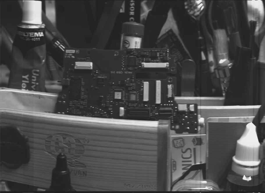
Imagine a regular camera first. The camera projects the 3D scenery onto a 2D sensor (CCD, CMOS, film, imaging plate, etc.) through a lens. The lens captures a smaller section of the 3D scenery according to its field of view (FOV). Now imagine removing almost all the columns of pixels from the 2D sensor, and keeping only a single one in the centre. Now the camera does not see the whole field of view of the lens, but it only sees a thin 1D line at the centre of the FOV. So, instead of a CCD matrix, now there is only a CCD line. Exactly what this TCD1304 is. This is illustrated in the image to the right. The whole 3D scenery is my workbench. The camera only sees a small section of it, according to the FOV rendered by the lens. This FOV appears on the captured image as the 2D projection of the 3D scenery. This scenery is then further cropped to keep only the pixels in the centerline to mimic what a linear CCD array (TCD1304) would see.
The CCD has 8 um tall and 200 um wide pixels; 3648 of them. So, in the case of a full-frame camera (24 mm x 36 mm), this single column of pixels covers the centre of the projected image with 3648 pixels. And here comes the fun part. This 24 mm x 36 mm rectangle is the size of the sensor or the film, but not the actual image projected by the lens. The lens projects a circle, and to cover the rectangle, it has to project at least as large a circle as the diagonal of the rectangle. After using the Pythagorean theorem, the diagonal turns out to be 43.26 mm. So, actually, at the centre of the frame, the visible image is not 24 mm tall (as the height of the sensor or film), but in fact at least 43.26 mm. And this is fantastic news because we can utilise the full 29.1 mm length of the sensor area. This, in fact, renders the nominal FOV of a lens larger. The FOV or focal length of the lens is defined for a full-frame sensor. Similarly, when a full-frame lens has a crop factor larger than 1 when it is used on an APS-C camera (a 35 mm lens produces roughly the same FOV on an APS-C as a 50 mm on FF), it works the other way around, too. The full-frame lens here should have a crop factor smaller than 1 (something, like 0.82) when it is used with a sensor that can capture a larger portion of the projected image.
So, if we put the sensor in the centre of the image plane, the TCD1304 will only see a single line of the projected image. If we were to move the sensor across the whole plane’s horizontal axis, we could capture the whole 2D image, and this is essentially a scanner, which I already attempted to build some years ago. But now, I take a different approach. Instead of moving the CCD, I keep it fixed in the centre, and I rotate either the whole camera or the subject, or I take pictures of subjects that move in front of the camera in a linear trajectory (passing car, train, etc.). By either rotating the camera or the subject, I will be able to capture panoramic pictures of the subject or scenery. If I rotate the camera, I can capture a 360° image of the scenery, and if I rotate the subject, for example, a tin can, or anything fairly cylindrical, I can scan its whole curved surface (face).
Just to clarify, this is not at all a new thing. Even satellites, like the Pioneer 10, used a similar technique to capture images. At that time (60’s to 80’s), this technique was widely used because the 2D CCD/CMOS arrays either did not exist or were very rudimentary. Then, they finally took over, but the 1D (line) sensors still stayed relevant in some niche applications. They are still used to take images at the finish line of races and can result in very interesting photos. And of course, there is a small group of photographers in various branches of photography who have great artistic talent to utilise this technology for taking interesting pictures. Furthermore, the industry also uses these cameras because they can operate at extremely high speeds, and they are ideal for inspecting surfaces and other features.

My TCD1304 breakout board that fits on an STM32F401CCU6 microcontroller.
Implementation
As I said, I used my TCD1304 standalone board with an STM32F401CCU6 microcontroller. The microcontroller sends the data to the computer via USB, where a custom software I wrote in C# captures the lines and arranges them into an intelligible picture. I optimised both my STM32 firmware and my C# software, and I can fetch lines at a rate of nearly 70 FPS. It makes scanning a 360° image relatively fast.
But wait, there is more!
I added a 2.8” TFT LCD (320 x 240) with an SD card module to the system and made it work! So, this is really a camera now. It can show the live image with a high frame (line) rate on the display, and at the same time, it can save the lines on the SD card. The user can generate a preview scan without saving the contents on the SD card, and if the light and focus conditions are acceptable, a new scan can be started, and the contents can be saved on the SD card. As of now, the image is saved on the SD card in binary format. So, if we want to convert it into a viewable picture, we need to convert it into a bitmap on the computer when we view the contents of the SD card. Each picture is saved in an individual file, so they can be distinguished when they need to be processed.
The image is saved on the memory card as-is. This has a few implications. First of all, as I mentioned, the CCD is larger (29.1 mm) than the projected image of the full-frame lens along the vertical axis (24 mm). Therefore, the actual FOV captured by the linear CCD is larger than the default FOV of the lens. However, this does not matter, when I print the lines on the display, I print the full captured line; I just downscale it to 240 pixels, which is the height of the display.
Also, there is no auto brightness or contrast adjustment during capturing. This can result in poor contrast when printing the image on the display, but the image can be improved on the PC in post-processing.
The scanning is infinite! This means that the generated output image is 3694 pixels tall and X pixels long, where X is up to the user’s discretion. This must be treated with care because the files could grow large easily. I added a frame counter to the top right corner of the display, so the user can keep track of the number of lines scanned. Also, since we don’t know the scan length in advance, the X axis is kept as-is, and it is not scaled down. So, it can display 320 lines at a time. But once the display is full, it wraps around, and after the 320th column is populated with a scanned line, the next scanned line will be placed in the 1st column, and the previous line in the 1st column gets replaced. This strategy allows us to scan indefinitely without any magic algorithm or guesses to predict the necessary downscaling of the X axis.
The innards of the camera
The fully assembled camera with a lens
Hardware
As mentioned, the key component, the image sensor, is the TCD1304 linear CCD. The sensor is driven and read by an STM32F401CCU6 microcontroller. This is a fantastic microcontroller with a very strong hardware and many peripherals. It has many timers, which are crucial for driving the CCD. It has a high-speed ADC, so the pixels of the CCD can be captured properly, and it has native USB, multiple SPI buses and many GPIO pins, which are all appreciated in this project.
The presence of multiple SPI buses is a blessing because I used several PA pins, which coincide with the pins of the SPI1 bus. So, I simply use SPI2 instead. The SPI is used both for the display and the onboard SD card reader. Before any questions or comments, yes, I know that this display also has a touch module, but I found it unnecessary, and I prefer physical controls. So, I do not use the touch module of the display.
Instead, I used my old debounced rotary encoder module to control the camera. Software-wise, the camera can run in capture and preview mode, plus we can change the integration time (SH timer’s period) and the capture frequency (basically, the FPS). So, there are not many things to take care of, and it is easy to implement an interrupt-based encoder handling.
The whole camera sits in a 3D-printed housing. The housing consists of two shells: the main camera body and the rear panel. The camera body received a metal M42 flange I recovered from a broken old film camera. This body also accommodates the sensor, mounted on my TCD1304 sensor board, the STM32F401CCU6 microcontroller and the rotary encoder. I mounted the MCU in a way that its USB port faces the hole on the bottom of the housing. I did not implement a battery in this initial version just yet. Instead, I power the MCU from a power bank, and then the MCU provides power for the rest of the components. A future iteration might receive a built-in lithium battery with charger and everything, but I am planning to make further iterations of this camera, and therefore, the battery is not at the top of the priorities. The rotary encoder is attached to the housing in a similar way to the exposure buttons on regular cameras. But, aside from starting and stopping the capturing process, it also has other functions.
The rear panel accommodates the display module. The SD card slot is accessible from the top. The SD card sticks out a little bit, but in order to keep the housing sleek, I was OK to accept this “issue”. It is a DIY gadget, not a mass-produced consumer product anyway.
There is one more thing I haven’t implemented, and again, it is on purpose. I could have added a stepper motor setup to the microcontroller, so it could drive a stepper motor that is synchronized with the capturing of the frames. For example, this would work very well for scanning panoramic images or driving a rotary platform to scan cylindrical objects. However, if I wanted to add it to the camera directly, I would have encountered the issue of power supply because the stepper motor driver requires a higher voltage (~12 V) than the microcontroller and other peripherals (5 V / 3.3 V). So, for now, I just have a totally independent driving based on my stepper motor platform. It does the job for now, and later, when I know exactly what I want with this camera, I might incorporate a stepper motor.
The TCD1304 PCB mounted in the enclosure.
The debounced rotary encoder module from an earlier project
Results
I also designed and built a simple but sturdy rotating platform, both for rotating the camera and for rotating cylindrical objects like tin cans and containers. The platform is mainly 3D printed, and it is driven by a sNEMA23 stepper motor. To not spend too much time controlling the stepper motor, I just used my stepper motor development platform. I reprogrammed the microcontroller and implemented a simple driving routine that drives the stepper motor at a certain speed defined in steps/s.
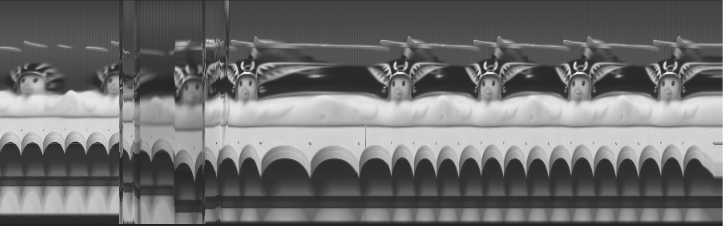
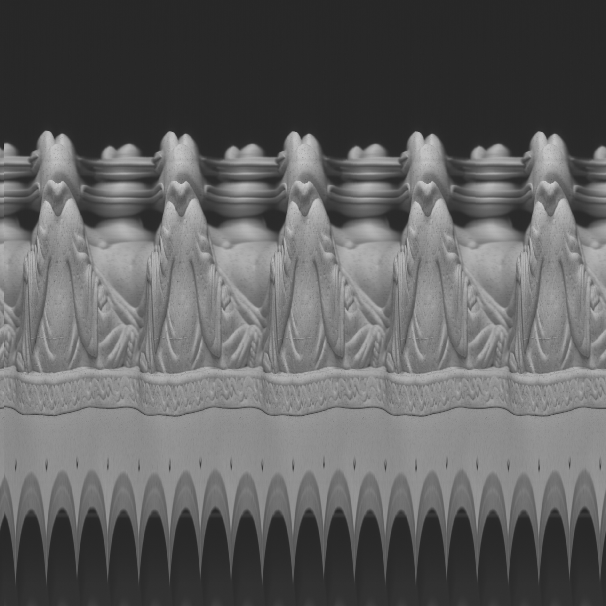
For other fun pictures, I repurposed my linear actuator and used it to move the subject or the camera horizontally. I only cropped and/or resized the images, but I haven’t modified their brightness and contrast, so the pixel levels are according to the output of the CCD. Some lines look odd because they contain overexposed pictures, and when the CCD goes to saturation, it can produce weird pixels or even lines. The CCD and/or the readout circuitry do not have a very good dynamic range, so scenes with homogeneous lightning look much better than scenes with large differences in bright and dark areas.

Consider using my affiliate links to buy the relevant parts!
Get the PCB using PCBWay!
