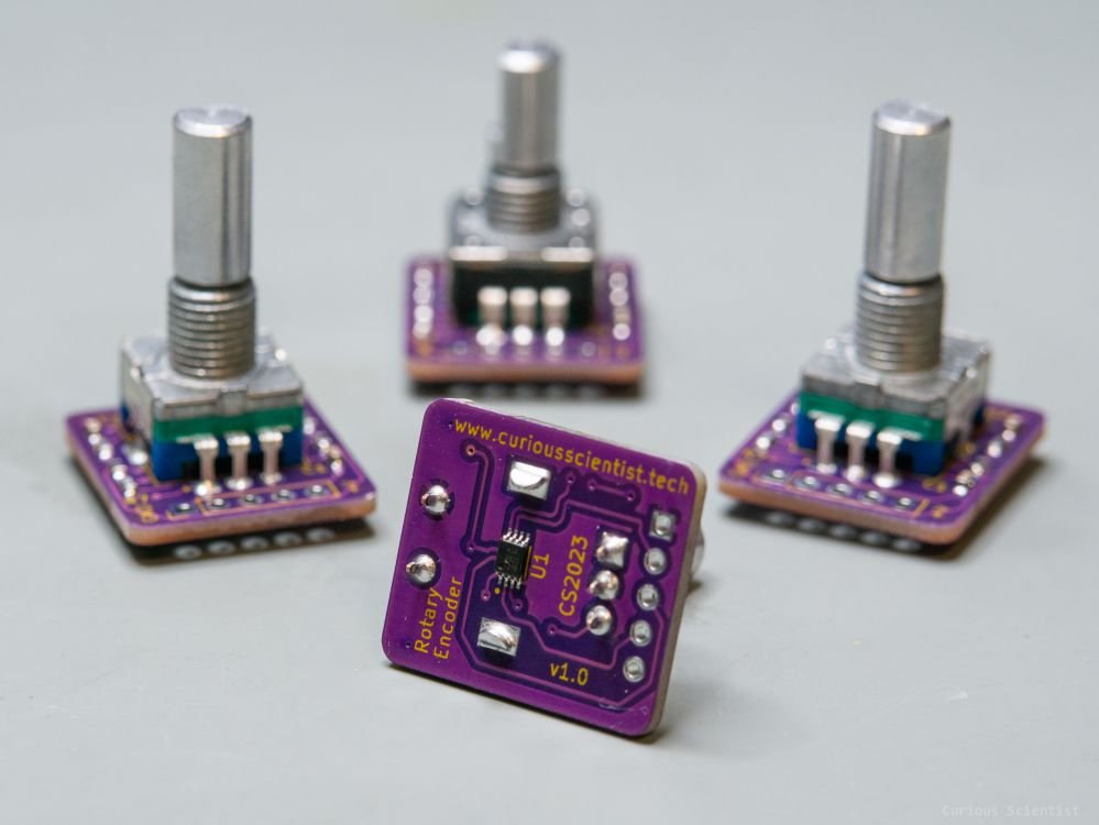
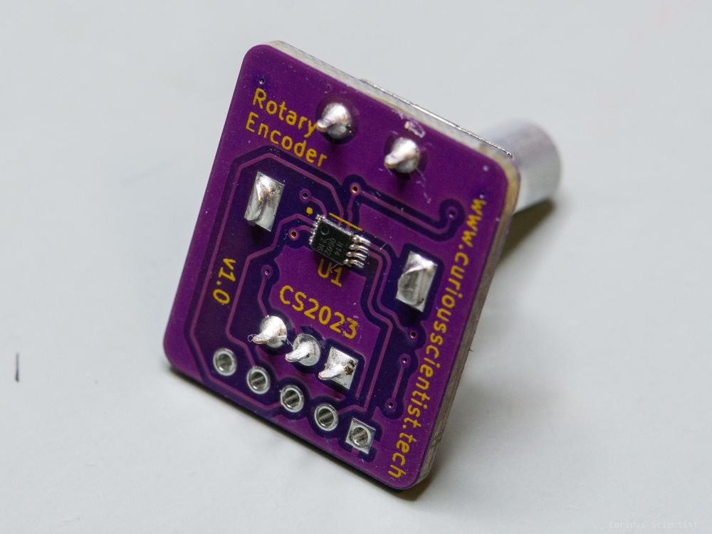
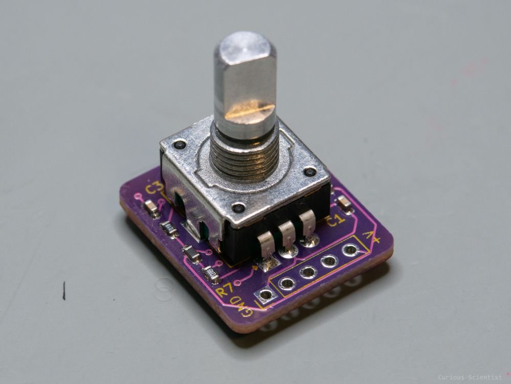
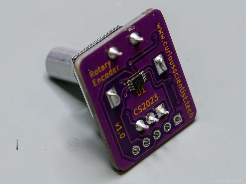
Rotary encoder module with Schmitt trigger
In this video, I show you my approach to making a rotary encoder module. One can buy different rotary encoder modules on the internet for a very cheap price, and I have been doing that for years, too. However, I wanted to come up with my own version of such a module. Typical modules either only contain some pull-up resistors, or they even have RC low-pass filters, but I haven’t encountered any that have a built-in Schmitt trigger circuit that allows to produce perfect square waves.
Probably many people would say that one could debounce a rotary encoder with software, but I wanted to avoid it as much as possible and provide the microcontroller with an as clean as possible signal. Maybe it is an overkill, but I had fun designing and assembling the circuit and I also learned more about the components used in the circuit.
About the circuit
Debouncing is a recurring question on different electronics forums. Some people prefer hardware debouncing, while others prefer software debouncing. Actually, it is nice that people do not agree on a single solution because we can learn a lot from the two groups’s discussions.
Based on my experience with encoders and encoder modules, I wanted to build my own circuit that does not only have passive components (capacitors and resistors) but also has an active component, a Schmitt trigger inverter. I wanted to be sure that my circuit would generate perfect square waves when the rotary encoder was rotated. No bouncing!
First, let’s look at the simulation I made based on the circuit I built.
The rotary encoder is simulated by a push button. When the circuit is in its default state, the current flows towards the input of the Schmitt trigger (left chart) and output voltage appears on its output terminal (right chart). This circuit also charges the capacitor (100 nF) through the two resistors in series (10k + 1k).
When I briefly press the button, the circuit between the power supply and the ground is shorted through the 10k resistor. There is also a short created between the capacitor and the ground through the 1k resistor. The capacitor quickly discharges through the 1k resistor and since the input voltage of the Schmitt trigger drops below the threshold value, its output also drops to zero.
When the push button is released, the capacitor gets charged. The charging time depends on the value of the capacitor and the resistors in the circuit. As you can see on the left-hand side chart, the voltage slowly rises on the input terminal of the Schmitt trigger circuit. During this process, the output is still zero because the voltage hasn’t yet reached the threshold level. Once the threshold is reached, the output of the Schmitt trigger goes high.
I also tried to produce some bouncing by quickly pressing the button. First, just a little burst, then a longer one. You can see that as long as the voltage is below the threshold level of the Schmitt trigger, the output stays zero, despite the bouncing.

Falstad simulation of the rotary encoder
By playing around with the two resistors’ and the capacitor’s values and respecting the threshold levels of the Schmitt trigger circuit, we can adjust the charge-discharge cycles for a given application. Basically, we just need to think if the encoder will be rotated slowly or quickly.
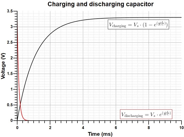
Charging a 100 nF capacitor through 11 kOhm resistance (10 k + 1k) with 3.3 V, then discharging the capacitor through a 1 kOhm resistor.

The output of the RC filter (yellow) and the output of the Schmitt trigger circuit (purple). We can see that the voltage drops to zero almost immediately and it takes about 5 ms to recharge the capacitor to the supply voltage. This is similar to the behaviour expected from the calculations (shown on the left side).
In the examples on the right side, I collected some interesting signals that I measured when I recorded the video. I also added some extra pictures that I captured “off-record”.
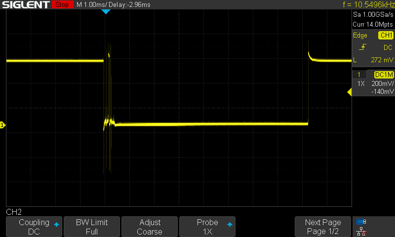
The first picture perfectly illustrates the bouncing. The signal cannot reach the low level properly, after it falls for the first time, it returns to the high level several times. A microcontroller would register those peaks as pulses which would generate false pulses. The goal of this project is to eliminate these peaks.
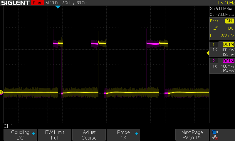
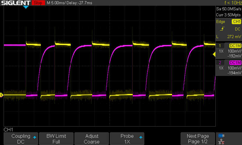
Then, in the next few pictures, I show the typical signals that can be used to determine the rotation direction.
I also show the signal before and after the Schmitt trigger circuit. Once can see that the RC-filtered signal is already good enough, we can transform them into perfect square waves using the Schmitt trigger circuit.
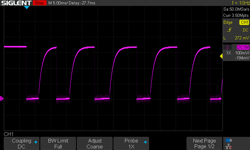
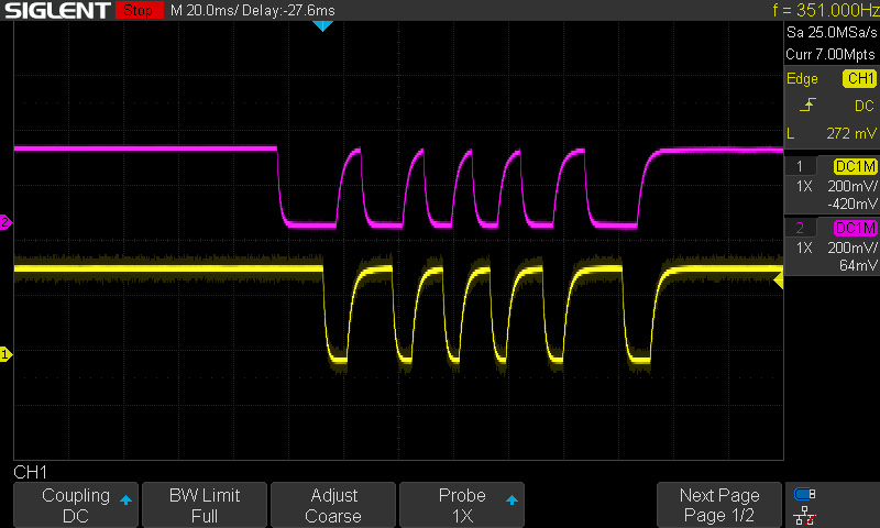
Finally, I show the two rotary encoder channels of the cheap module. We can see that the signal is quite nice. It can also be seen that it takes time to discharge the capacitor. The falling edge is not perfectly vertical but it has a small decaying part towards the zero voltage.


Relevant information
Get this circuit from PCBWay!