Improved miniature cloud chamber
In this video and article, I show you how you can build your own miniature cloud chamber. Unlike most of my video-article combinations, I compressed all the information into a Short, but the article contains a more comprehensive summary for those who want to see the steps in more detail. The advantage of this build is that it is relatively simple to build, it does not require any complicated parts, and it creates the effects on a relatively large surface area.
Introduction
I don’t want to spend too much time on the introduction of the cloud chamber as a device, because I did it in multiple videos. I built a similar, but smaller, cloud chamber before, and I also built a large one with a 20x20 cm effective area. So, apart from this article, I also recommend those two others. Anyway, the basic principles of a cloud chamber are that at its bottom, there is a supersaturated vapour layer formed. Then, when an ionising particle flies through the vapour layer, ionisation provides condensation nuclei. The condensation occurs along the path of the particle and makes spectacular lines and curves of “clouds” in the chamber. Typically, for DIY purposes, the vapour is alcohol vapour, for example, isopropyl alcohol (IPA). The supersaturated layer at the bottom, above the cold base, is a result of a steep temperature gradient in the chamber between the cooled base (-25°C or below) and the room-temperature top of the chamber.
Here, I am going to explain the small extra details that I could not fit into a short-format video. There are details that might be too obvious to explain or mention in the video, but they might not be obvious for everyone. I want to show you how I built the pieces together, and what is needed to successfully replicate my cloud chamber.
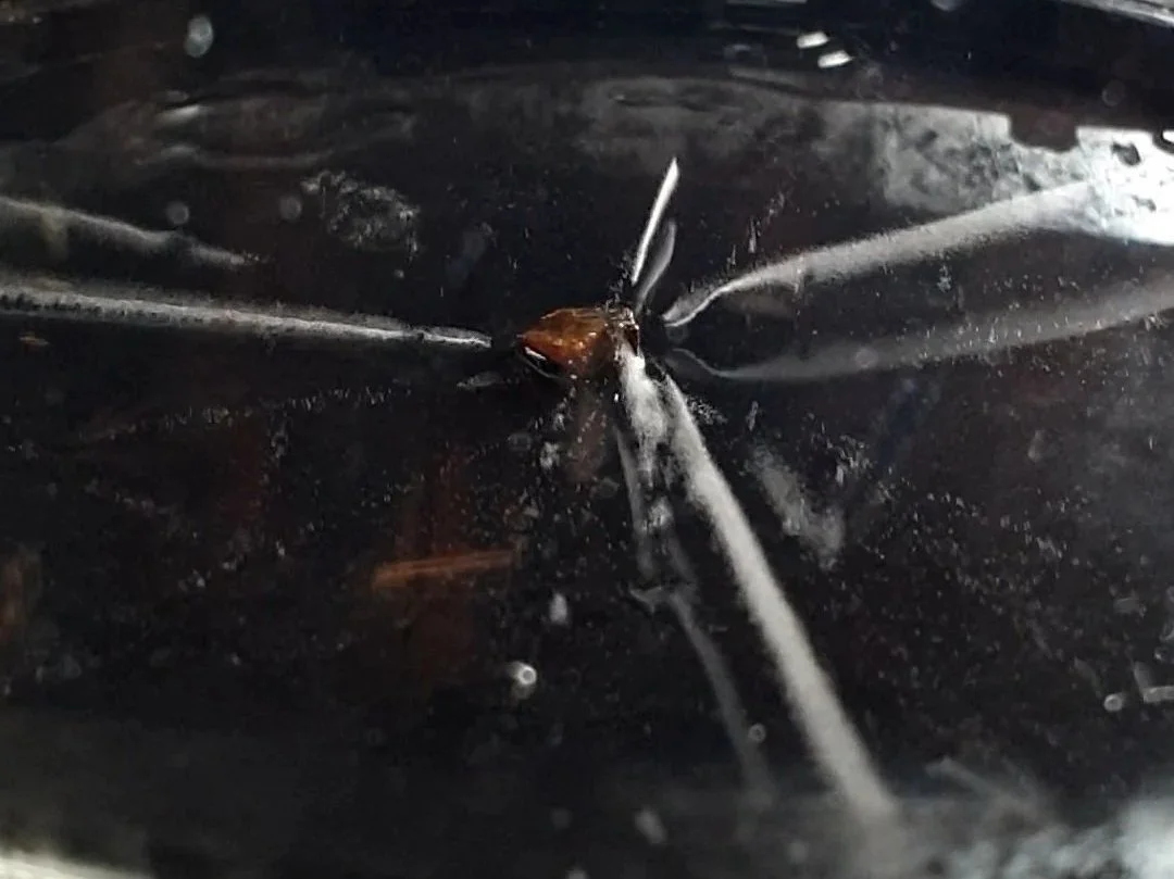
A thorium-containing mineral in the chamber.
The build
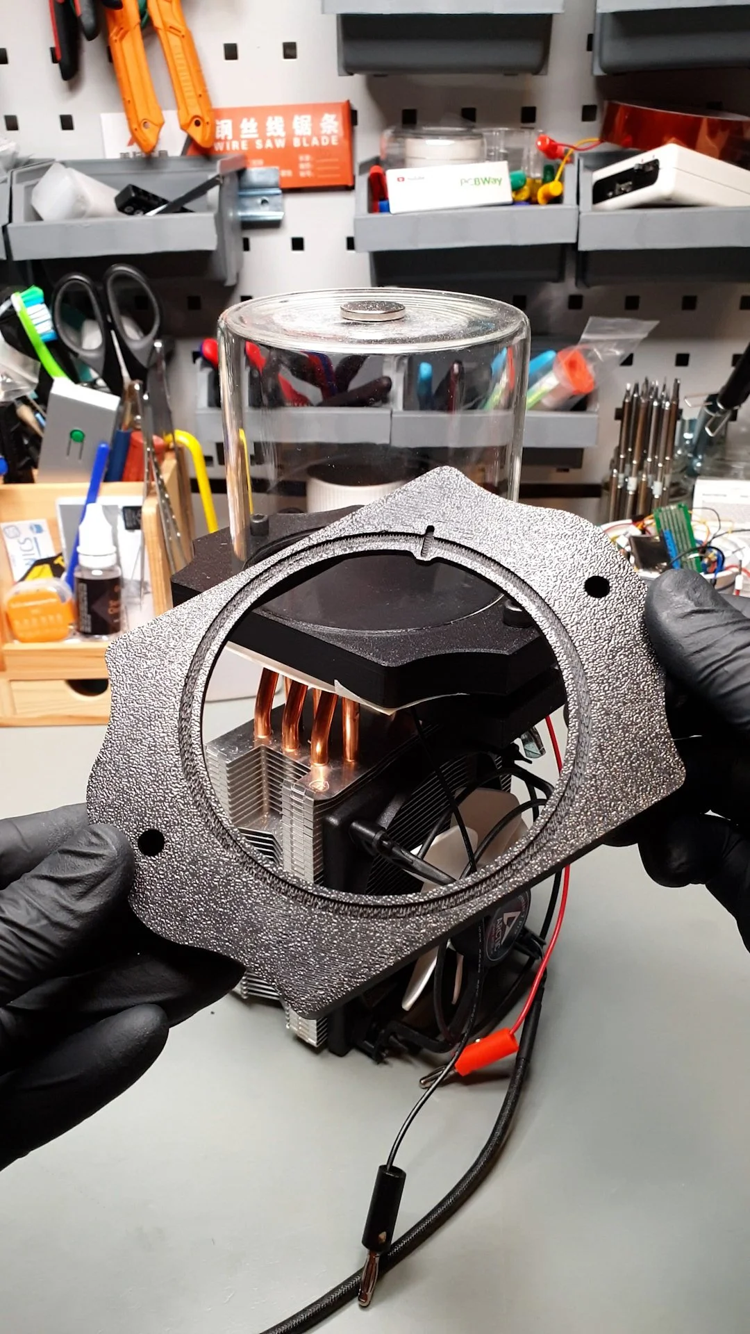
The build, apart from the 3D-printed parts, is entirely based on off-the-shelf components. The main part is the top 3D-printed part that has multiple purposes. It holds the aluminium plate firmly. It holds the jar, the chamber. And it provides clamping on the Peltier cooler.
First, I cut the aluminium plate to size using a jigsaw, and I deburred the edges with a file. I removed the last fractions of millimetres with the file so that the plate tightly clicks into the 3D-printed frame. The top side of the plate that faces the chamber was covered by a black car headlight foil. The black surface creates a good background for the white vapour cloud. Plus, I used a foil instead of painting the plate because the alcohol might dissolve the paint. Installing the foil is a cheaper and cleaner process; it is also simpler than painting, especially at home.
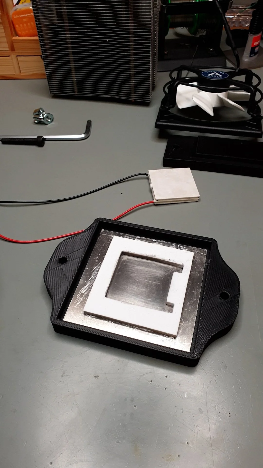
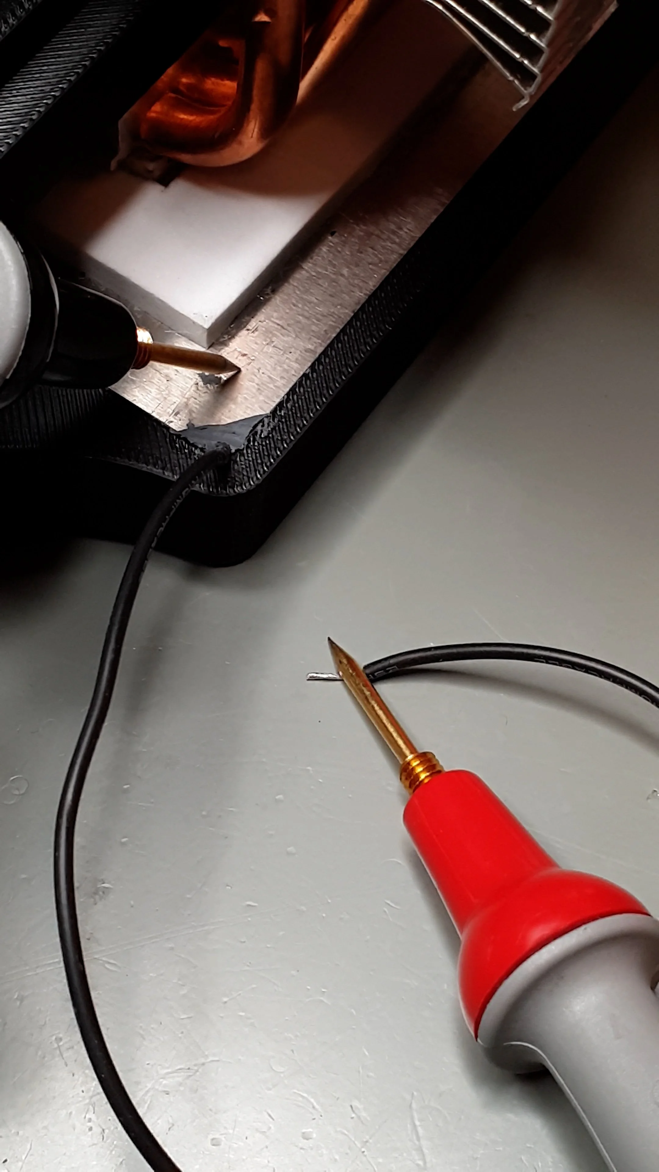
Then, I installed an insulating foam for the Peltier cooler at the centre of the aluminium plate. This foam also provides support for the Peltier cooler, and it helps with the alignment. Once the glue settled, I clicked the aluminium plate into the plastic frame. I carved out a tiny part of the plastic at one of the corners and squeezed a wire between the plate and the plastic frame. Then I fixed the wire in place with epoxy putty. This wire is necessary because I need it to connect the negative side of the high-voltage power supply to the plate. After the epoxy cured, I checked the connection with a multimeter.
Then, I applied high-performance thermal paste on the CPU cooler and on the cold side of the Peltier cooler. First, I squeezed the cold side of the Peltier cooler onto the aluminium plate. I slightly wiggled it while pressing it down to spread the paste evenly and squeeze out the excess paste. I used a Q-tip to remove the excess paste. Since the Peltier cooler was on the table, firmly sitting in the plastic frame, I pressed the CPU cooler onto the hot side of the Peltier cooler and repeated the “press and twist” exercise to spread the paste. One could have done it the other way around, but the CPU cooler is less stable, so it is more cumbersome.
Then, I carefully lifted the whole device and rotated it so it was resting on the CPU cooler. I installed the two screws and the crosshead that clamps the whole cooler and base together. I used winged nuts to make it easier to tighten the screws. The crosshead can slightly bend, but the screws should not be overtightened because the thin ceramic plates of the Peltier cooler can be damaged.
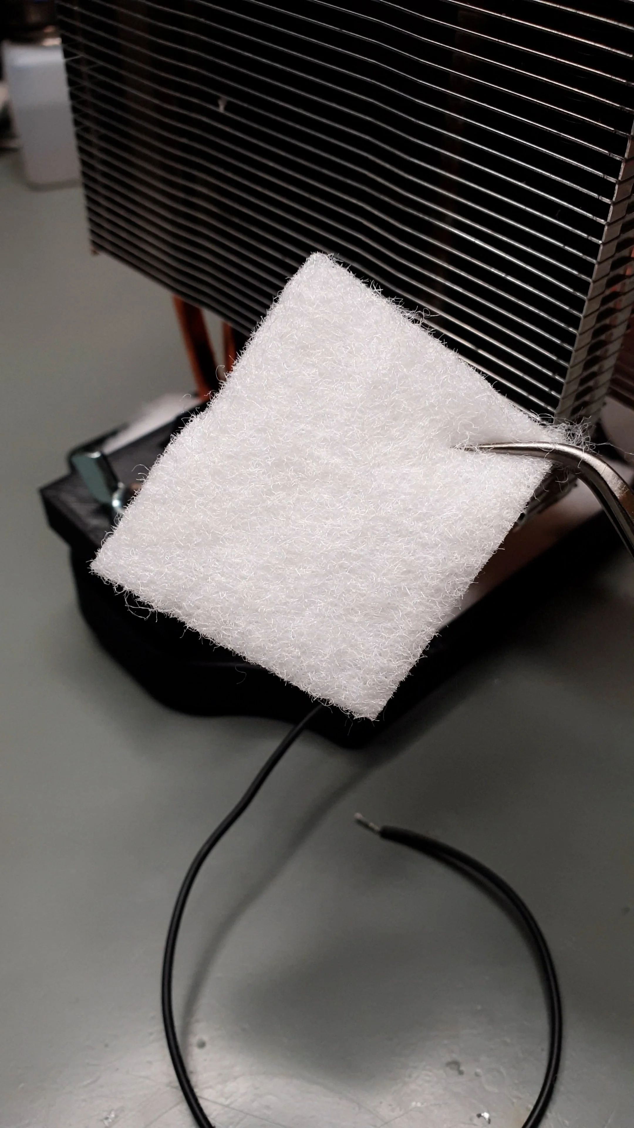
Finally, I cut some polyester wadding to size and carefully tucked in to the backside of the top plate to insulate it as well as possible. I also covered it with some masking tape so it does not fall out.
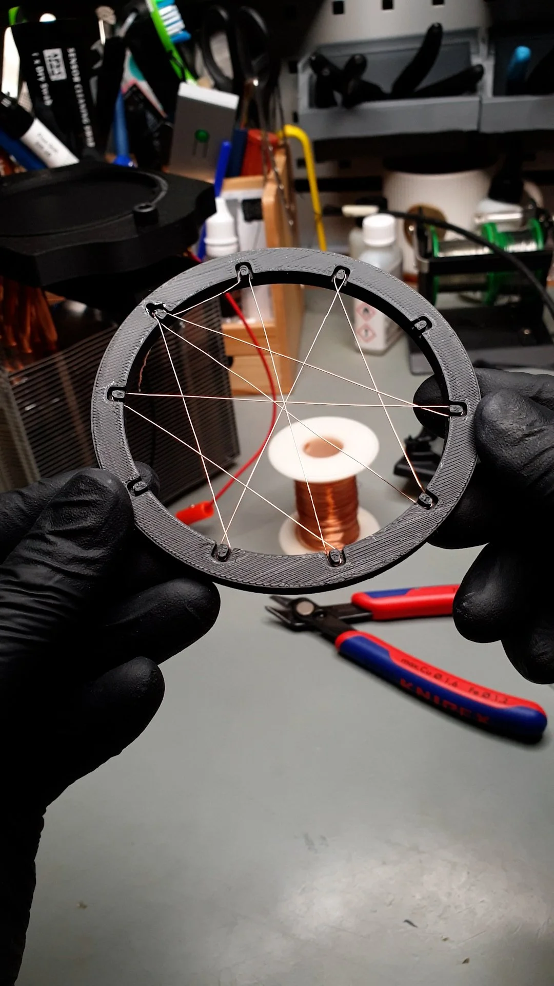
Another “mechanical” part that I had to prepare was the HV grid. I designed a ring that fits almost perfectly in the jar. The ring was shaped so that it has small grooves along its circumference that can support thin wires. I used a thin, enamelled copper wire and folded it around the ring, forming a spider-web structure. The wire of the grid is then attached to an insulated wire that goes through the small channel on the top plate.

Electronics
I picked the components so that the whole system can run from a 12 V 10 A power supply. The sweet spot of the Peltier cooler seems to be at around 12 V. So, the only thing that we have to ensure is that there is enough current. At 12 V, the Peltier cooler draws a bit above 5 A. To be on the safe side, let’s say it draws 6 A.
The fan that blows fresh air through the fins of the heatsink runs on 12 V. It consumes around 200 mA, so it is not a big load for the power supply. The only thing that matters is that it runs at 12 V.
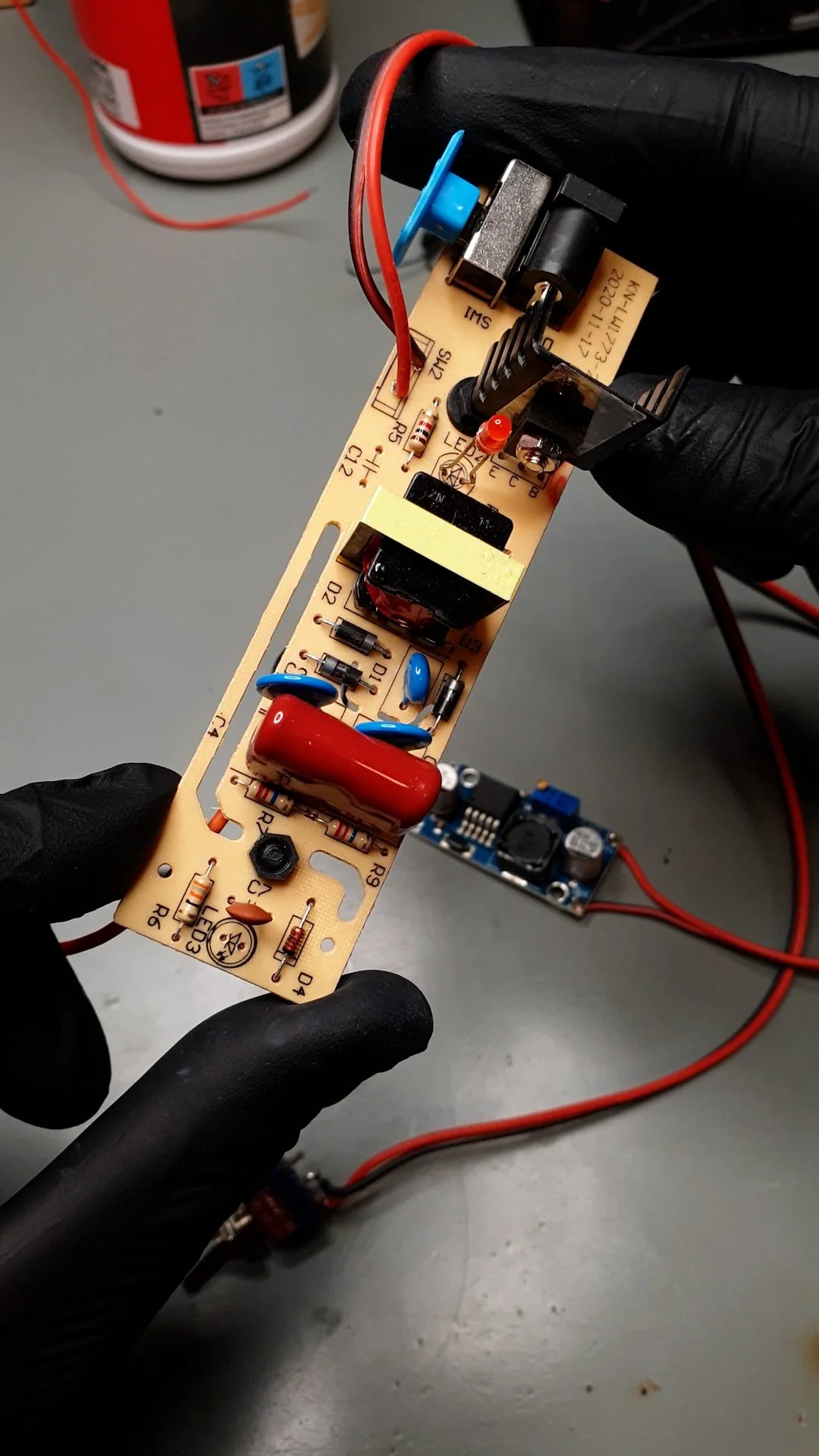
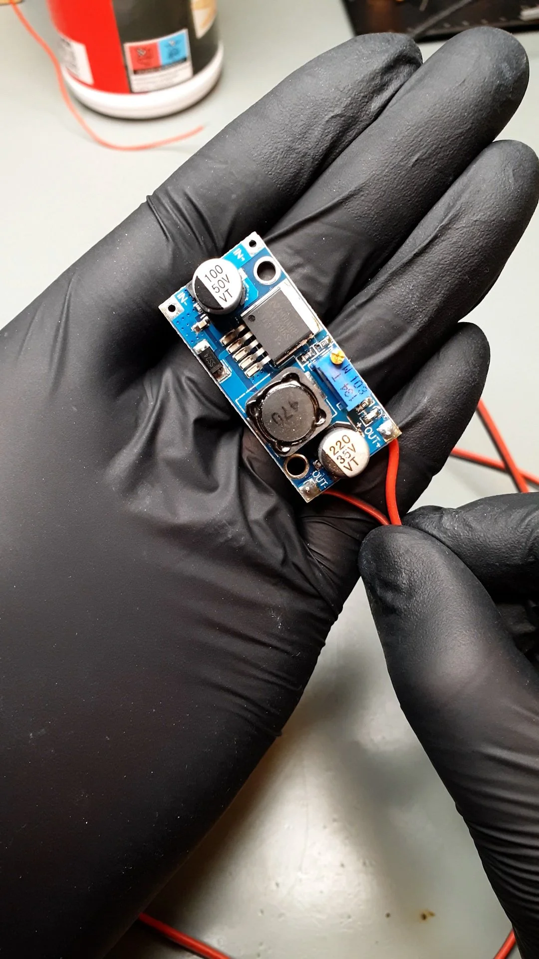
The trickier part is the HV power supply. Originally, it was designed to be powered from a 18650 lithium battery, which was embedded in the handle of the mosquito swatter. This has a maximum voltage of around 4.2 V. So, I had to somehow generate 4.2 V from 12 V. I picked an LM2596-based DC-DC converter for this task. Before connecting it to the HV power supply, I adjusted the potentiometer on it until I was able to read 4.2 V on its output. When the HV power supply is on, the DC-DC converter draws around 200 mA.
So, in total, the whole 12 V rail is loaded with ~5.4 A.
If you want, you can find a 12 V LED strip and add it to the system. In that case, you have to consider a few hundred extra milliAmperes, which is drawn by the LEDs. I used a video light to provide lighting for the chamber, but an LED strip could also work. Or, even a regular flashlight could work if it has a narrow beam.
I powered my chamber using my benchtop power supply, but it is also an easy way to power it with a switching power supply or a wall wart. Everything can run in parallel from the 12 V output of the power supply.
Bill of materials
Below is the bill of materials. Where applicable, I provided an affiliate link for the product. I put the current price of the products next to each item. These might not be the same when you look at them because they might be influenced by ongoing campaigns and stuff. But it is a good indicator.
6-heatpipe CPU cooler ($32)
Mosquito swatter ($5)
Banana plugs ($2)
2 mm Aluminium plate ($4)
The total cost of the build is not more than $100. I think it is a relatively low price for its cool factor, and if you think about it, this is a device that once earned a Nobel prize.
If you want the 3D printed parts, please consider joining my YouTube Channel’s membership. Members get access to extra content.
If you found this content useful, please consider joining my YouTube channel’s membership or leaving a donation.
Also, please consider using my affiliate links when buying relevant gadgets.
FAQ
The list below is some responses to questions I got on YouTube earlier on cloud chamber videos:
Yes, the CPU cooler is upside-down, but it does its job as it should. It cools the hot side of the Peltier cooler sufficiently (otherwise the chamber would not work…).
Yes, the cold plate reaches below -25°C, I measured it. Also, if it couldn’t reach this temperature, the experiment would not work.
There is no need to submerge the heatsink in water. The fan removes the heat just fine, and the cooling is properly sized for the Peltier’s heat dissipation.
There is no need to use water cooling, see above.
Even if it seems that I put too much thermal paste on the cooler, when I assembled the device, the excess got squeezed out. It is fine.
There is no need for radioactive particles to see trails. We are constantly surrounded by the natural background radiation and cosmic rays, and they interact with the cloud chamber.
No, the natural background radiation and cosmic rays are not dangerous.
Yes, a magnetic field around/inside the chamber could produce curved trails. However, based on the size of the chamber, you might need a very strong magnet.
The mineral I used is a piece of thorite. I sourced from a shop that provides supplies for classroom science experiments. Check it with your local science shop.