Stepper motor PID control using a TMC2209 and AS5600
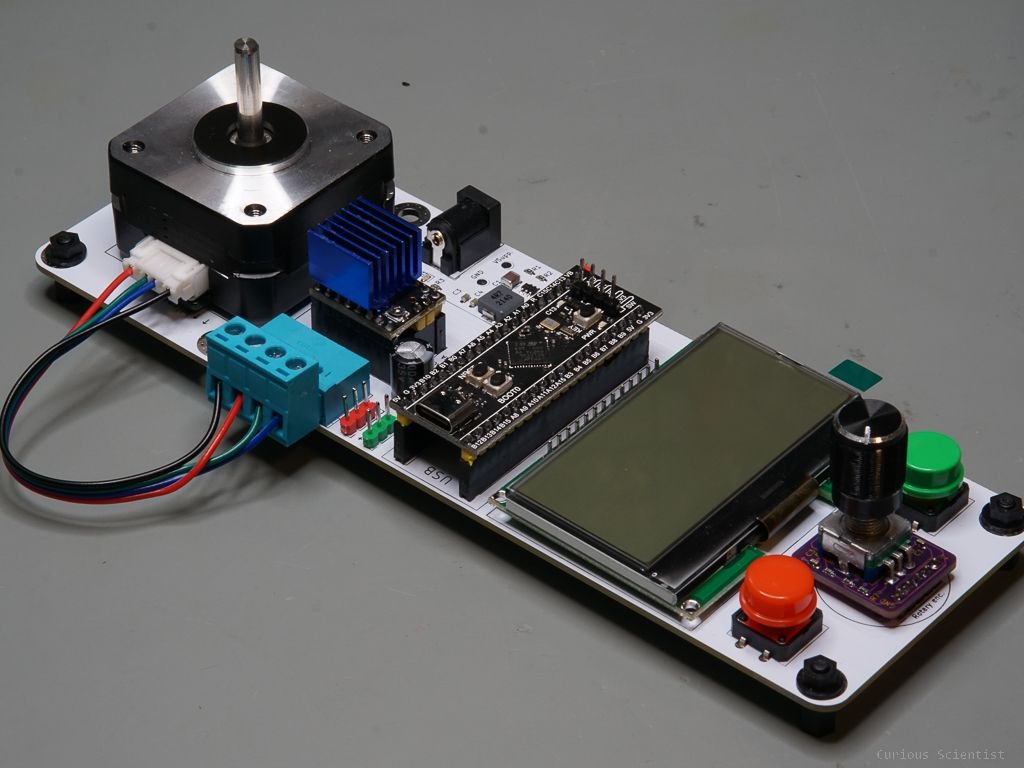
In this video, I show you how to implement a rudimentary PID control for stepper motors using a TMC2209 stepper motor driver and an AS5600 magnetic encoder. Thanks to the PID algorithm, the motor can find its way to the target and it can maintain its position, even if the shaft of the motor is rotated by an external force.
Basic principles
In my previous video, I already introduced my stepper motor development platform. Its purpose is to allow users to quickly and easily develop Arduino-compatible code to control stepper motors in different scenarios.
In an older video, I already showed the basic principles of a PID control setup using a DC motor and a magnetic (Hall) encoder.
In this project, this idea is implemented using a stepper motor and a magnetic (absolute) encoder. What we want to achieve is the same as we want with DC motors. Based on the signal of an encoder that provides the microcontroller with the position, we generate a signal that controls the speed of the motor. The speed is proportional to the distance between the actual position of the motor and the target distance (setpoint). When using DC motors, we typically generate a control signal which is the result of the PID equation. This control signal is then converted into a direction and a PWM value which is then passed to the DC motor driver that drives the motor. The microcontroller regularly checks the position of the motor, and recalculates the control signal and then provides the corresponding PWM value to the motor driver. This is iteratively done until the target is reached.
In fact, we do the exact same stuff with stepper motors, but we respect the fact that the principles of a stepper motor and the encoder we use are a bit different.
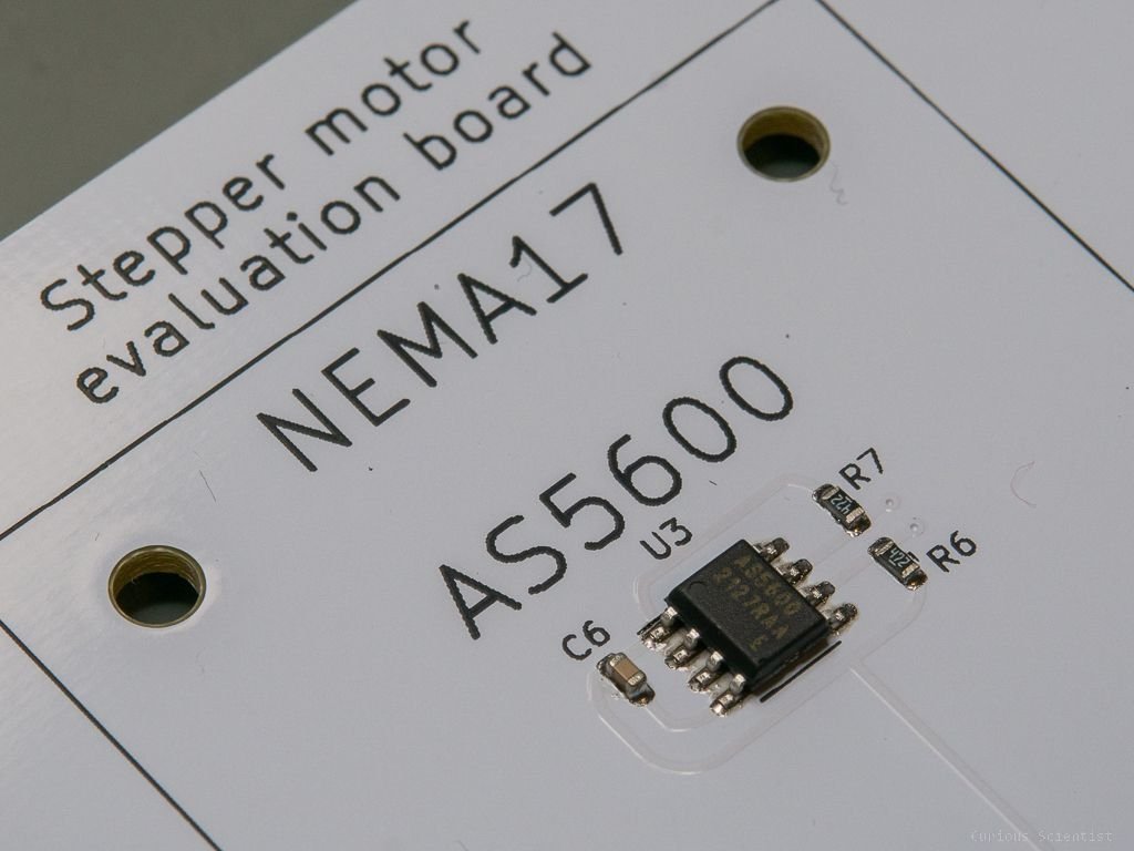
First, we use the AS5600 magnetic encoder. Due to its nature, it has a finite resolution which is about 0.088° (360° / 4096). This could mean that we need to introduce some tolerance, otherwise the motor won’t arrive at an exact position.
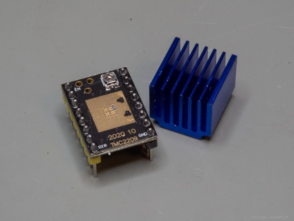
Then, we also have to keep in mind that the motor has a finite resolution as well. Using no microstepping, the motor has 1.8°/step resolution. So, if we try to have a precision below 1.8°, we might find ourselves in trouble. Luckily, the TMC2209 has a default of 1/8 microstepping which means that one step is divided into 8 sub-steps. So, instead of 200 steps/turn, the motor does 1600 steps/turn. Or, its angular resolution becomes 0.225°. This is nice because we can approach a position with a much finer tolerance. Actually, we could achieve 1/256 microstepping which is 0.007°/step which is way below the AS5600 encoder’s resolution. So, we can approach our target (setpoint) with this resolution (theoretically, at least).
So, once we know the limitation of the system, we can just implement the same algorithm for a stepper motor as we implemented for a DC motor.
We read the position of the motor using the AS5600 magnetic encoder. The position is defined in degree angles in this example.
We calculate the PID control signal based on the current position and the target set point
We send an instruction to the motor driver (stepping speed)
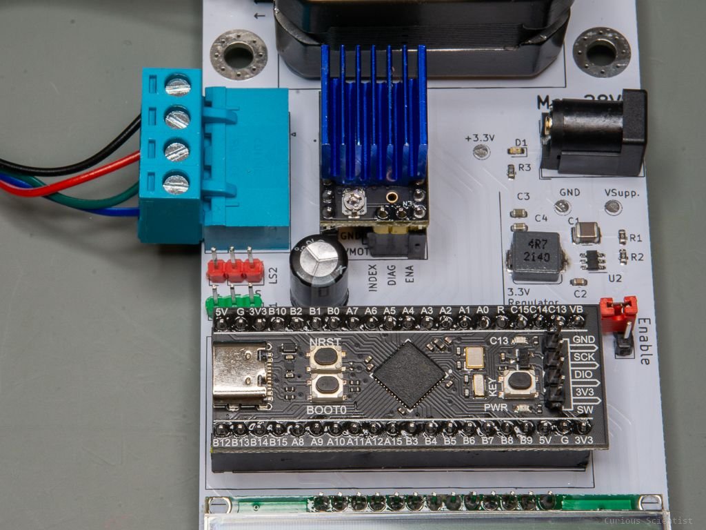
A neat trick I figured out using the TMC2209 stepper motor driver is that we do not need to use the STEP/DIR interface to drive the motor, but we can send instructions to the driver via the UART port. This is great because we do not need to continuously toggle the STEP pin, but it is enough to send an update of the speed value once in every iteration. This results in a smoother motor movement because the MCU is not loaded with constant toggling of a GPIO pin.
Extra resources
Please consider buying the parts using my affiliate links!
4-pin screw terminal connector
Diametrically magnetized magnet (5 mm)
Join my YouTube membership!
Find the PCB and other resources on my PCBWay project page!