AliExpress Finds - Part 2
It is time to continue the series with a new episode where I show you some useful electronics that I got from AliExpress. This is the second article in the series, and I will show you eight gadgets that might be interesting to you. I bought a stepper motor controller, mechanical and magnetic encoders, Peltier coolers, a power supply and a few other gadgets that might be useful in your toolkit as well!
TEC1-25506K10 40 mm x 80 mm Peltier cooler
This Peltier cooler is somewhat special because instead of the usual 40 mm x 40 mm size, one of its edges is 80 mm long. This results in a larger cooled area. Consequently, twice as large an area to be cooled (hot side) as well. It can produce up to 60°C of temperature difference between the hot side and the cold side, and as usual, there is a tradeoff between the temperature difference and the amount of heat that the Peltier cooler can pump from its cold side to its hot side. The rated voltage of the device is 30.5 V, and the rated maximum current is 6 A. Based on these parameters, it seems as if it were two TEC1-12706 devices connected in series. I could not find any good information on the Qmax (pumped heat) of the module, but based on the previous assumption (two 12706 in series), the device is able to pump around 100-110 W of heat from its cold side to its hot side. Since Peltier coolers are never operated at their maximum rating, after a little back-of-the-envelope calculation, in ideal conditions the device could transfer 40 W of heat while the temperature difference between the cold side and the hot side is 40°C. This would produce about 120 W Joule heat. So, the device’s hot side should be cooled with something that can get rid of at least 160 W of heat to allow ideal operation. Probably water cooling is the best solution.
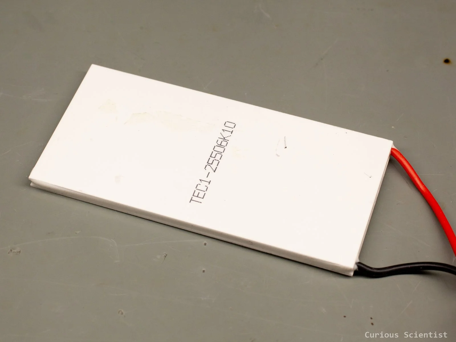
40 mm x 80 mm cooling surface: TEC1-25506K10
TEC2-19008 Multi-stage Peltier cooler
I used a slightly weaker version of this for my cloud chamber, the TEC2-19006. It is basically two Peltier coolers stacked together in one package. With this device, you don’t need to worry about achieving a good balance between the two Peltier coolers when you stack them. Just supply the device with the necessary power and let it work. It can accept up to 8 A of current, and its maximum rated voltage is 16 V. The maximum cooling power is 45 W. What is more interesting is that the temperature difference between the cold side and the hot side is above 80°. So, with a well-cooled hot side and minimum heat introduced to the cold side, reaching below -30°C or even -40°C should not be an issue. As with all Peltier coolers, there is always a tradeoff between the amount of heat moved from the cold side to the hot side and the achievable temperature difference between the two sides. So, you either can go very cold, or move heat, but not both at the same time. This device can help reach a bit colder temperatures while maintaining the usual 40 mm x 40 mm footprint and having just a single pair of supply cables. Really ideal for building DIY cloud chambers. Check out mine!
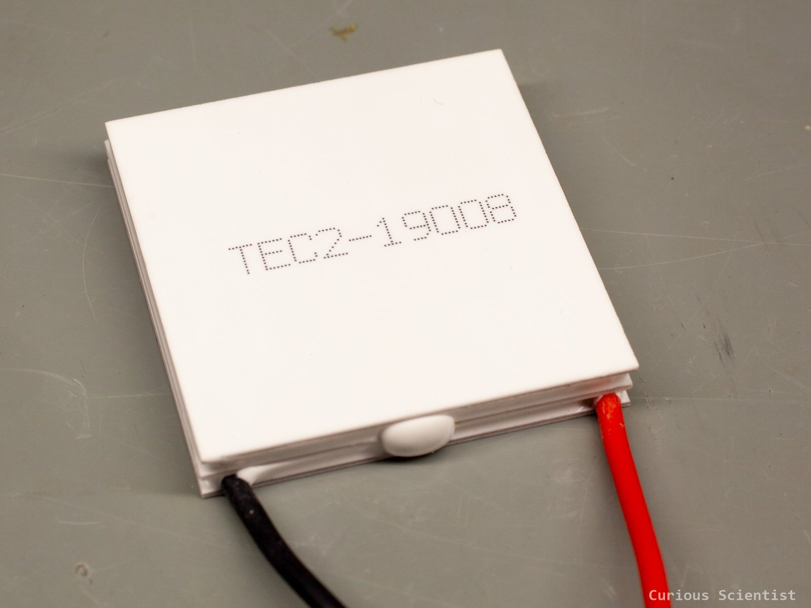
Multi stage Peltier cooler for low temperatures: TEC2-19008
WeAct Studio PD Power Mini V1 Buck
This is another interesting USB PD* power supply. Instead of using the PPS function like the previously introduced 5-36 V, 10 A power monitor with built-in display, this one uses a built-in buck converter, based on the SCT2450 chip. This chip can accept up to 36 V input voltage and can provide up to 5 A continuous output current. According to the datasheet of the device, we can get 1-20 V output voltage and up to 3 A current, and the manufacturer emphasises that maintaining 3 A current draw requires active cooling (“enhanced heat dissipation”).
*It is worth noticing that while the primary way of feeding the circuit is via a proper USB-C cable, the manufacturer provides a female DC terminal-to-USB-C adapter which allows us to supply 24 V from a power adapter. Also, you might wonder where the 24 V comes from a USB power adapter, but the USB PD 3.1 EPR protocol allows 24 V output.
Both the output voltage and the output current can be adjusted with 0.001 steps (“milli”). However, the accuracy of the output voltage is 10 mV, and the current is 2 mA. Yet, these are significantly better (smaller) step sizes than the PPS, because instead of doing PPS communication, here a real switching converter does the heavy lifting. So, the circuit controls the buck converter to achieve the desired output. The brain of the circuit is a CH32X035 microcontroller, which might be familiar to you from my previous 100 W USB-PD PPS power supply project. Here, the chip does the USB PD communication and manages the buttons and display to allow user interaction and controls the buck converter. There is a small 0.96” OLED display on the device and four buttons. The four buttons allow navigation on the display, and one of these buttons is solely dedicated to enabling and disabling the output power. The menu structure is simple. There are five memory slots where the user can store voltage and current settings. The device seems to remember these, even after power-cycling. The settings are easy to modify. Long-pressing the + or the - button enters edit mode. Pressing the S button moves the cursor over the next digit, and short-pressing the + or the - button changes the highlighted digit. Once the desired values are set, the user can exit by long-pressing the S button. Further, device-specific settings can be adjusted in the settings menu that can be reached by long-pressing the S button on the main screen. The output power is provided via a 4-pin 3.81 mm screw terminal, and there is a separate AUX power output of 5 V and 300 mA that is available via 2×4 2.54 male headers (pins). The main output has both overcurrent and short-circuit protection, whereas the auxiliary 5 V has only short-circuit protection. The device can even be controlled from a computer, but in that case the computer must have a USB output that is able to deliver the required power.
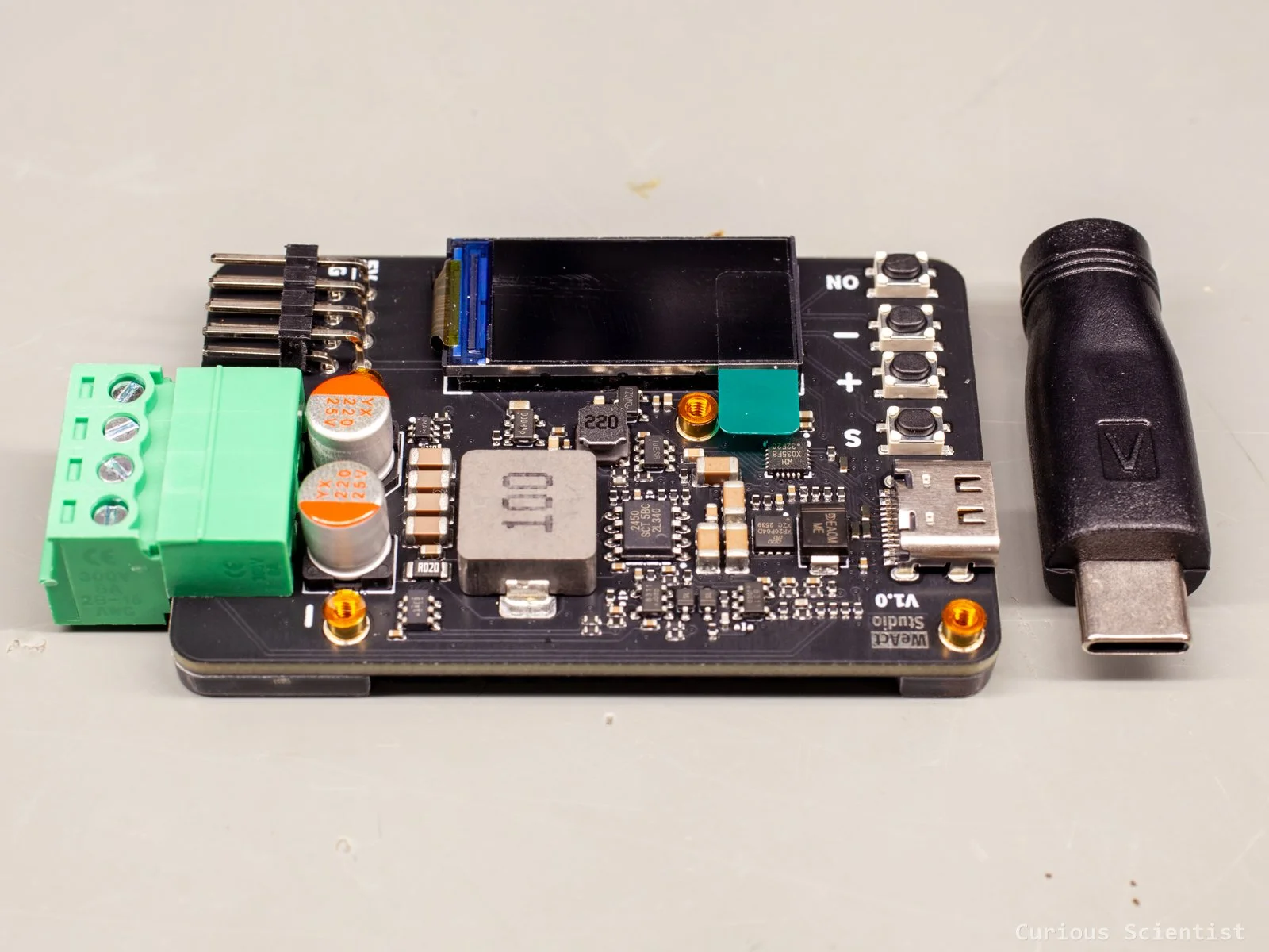
WeAct Studio PD Power Mini V1 Buck and its DC jack to USB-C adapter
5.5 V overvoltage protection circuit
This is a tiny circuit based on the AW33905 chip, which is an overvoltage protection (OVP) load switch. The chip features an ultra-low-resistance (~30 mOhm) nFET load switch. When the input voltage exceeds the OVP threshold, the switch is turned off promptly (~50 ns) to protect the connected device. The chip is able to conduct up to 5 A continuously. The specific version I have turns off above 5.5 V. It is ideal to protect microcontrollers that operate at 5 V. They typically allow a ±10% voltage swing around 5 V, so cutting off just above the 10% seems ideal.
Once the input voltage exceeds the OVP threshold, the onboard red LED turns on. This indicates that the threshold has been reached. To unlock the device, it must be powered off and then on again, or the voltage should be decreased to roughly 5.3 V or below. It is a tiny and cheap device, but it is worth embedding in your projects if there are sensitive components in it. Also, it is worth noticing that this circuit exists in many different voltage ratings, so you can pick the one that is suitable for your application.
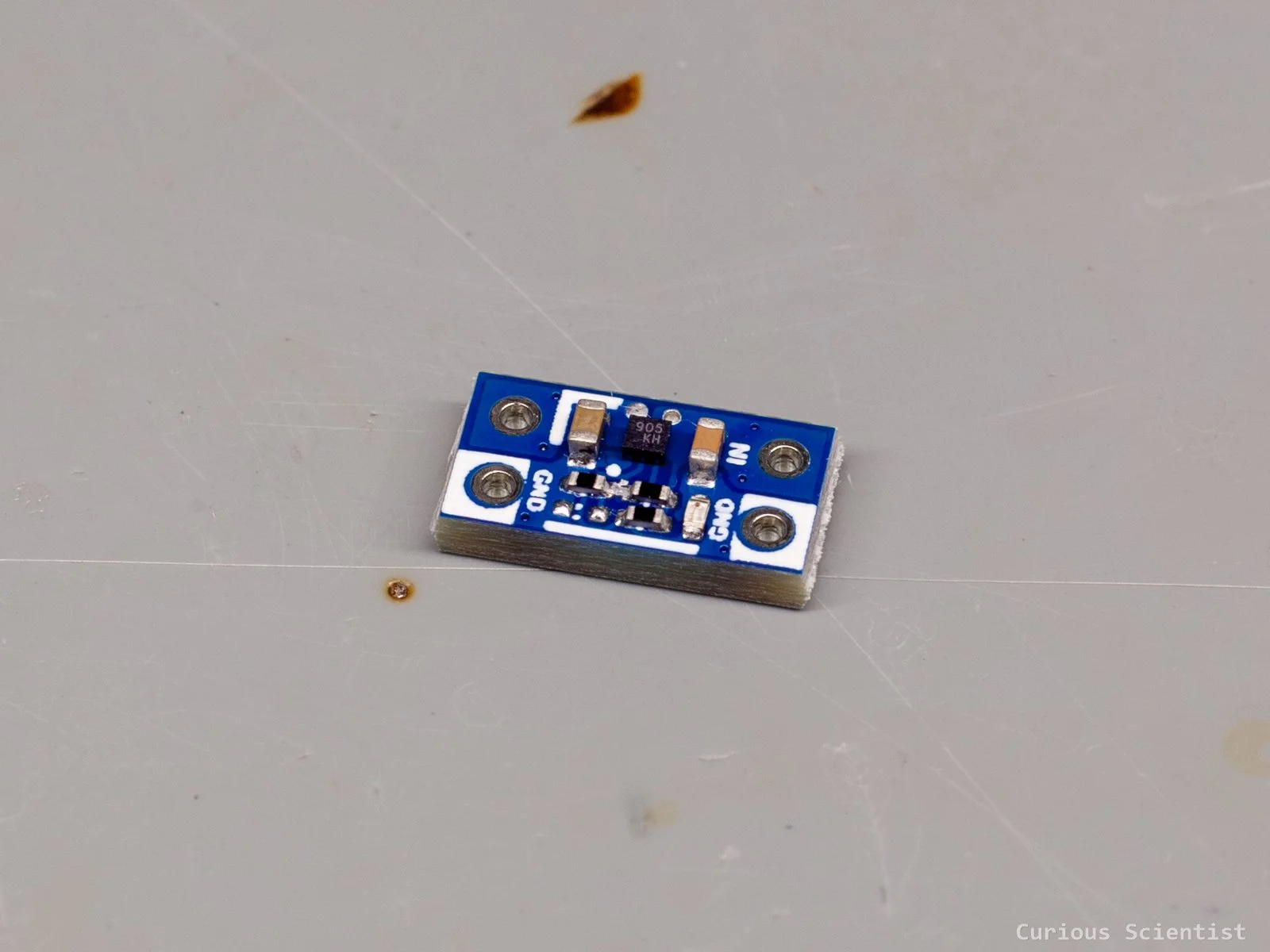
Overvoltage protection circuit
USB-C lithium battery charger with digital display
In the previous article, I already showed some lithium battery-related stuff, but I keep finding new ones, so here’s an interesting one. This device is made for single 3.7 V lithium cells. Ideal for 18650 batteries, or those typical 3.7 V LiPo pouch batteries. Charging can be done through a USB-C port, which allows a bit more than ~500 mA charging current. The USB-C port on the PCB is power-only, so there is no communication or voltage negotiation done by the device. It is a “dumb USB sink”. The charging is controlled by a “C60H”chip. And there is a small microcontroller, GX72116, on the PCB as well. If my detective work is right, this is a Padauk PFS122 8-bit microcontroller. It is probably used for driving the display based on the charge state of the battery.
The device is most probably recycled because it seems a bit used, and there are some additional wires on the PCB, and some of them were snipped. I suspect that these units are recycled from vapes. Two obvious wires are the red (+) and black (-), which are used for charging the battery. They are marked with B+ and B- on the board. However, there are two additional silver wires marked with O+ and O-, and three others: red (M+), blue (M0) and black (M-) in a group whose role is not entirely certain.
But guess what!? Vapes usually have built-in airflow sensors that are used to detect when the user tries to inhale the fumes. These microphone-looking devices detect airflow and close the circuit when airflow occurs. In vapes, this action is used to turn on the heating coils to produce the fumes. To produce these fumes, a high-temperature source is needed. This is achieved by running current through coils, often called an atomiser. So, the leftover 2 silver wires marked with O+ and O- are probably used for this purpose. The O- pin is directly connected to the battery’s negative pole, and the O+ pin goes to an A5SHB High-side MOSFET’s drain pin. Then, this MOSFET’s source pin is connected to the battery’s positive pole.
When the M0 pin is touched, even with bare fingers, the device gets activated. The display turns on and shows the battery charge (battery icon) and, a bit later, the vape cartridge percentage (waterdrop icon), and at the same time, it also activates the MOSFET, and the battery voltage appears between the O+ and O- pins. The output is controlled by the microcontroller, and it is not possible to keep the O+ under voltage indefinitely. The voltage briefly appears on the output and then slowly decays.
So, the vape part is not really usable, but the rest of the circuit, the charger and status indicator part, is quite useful.
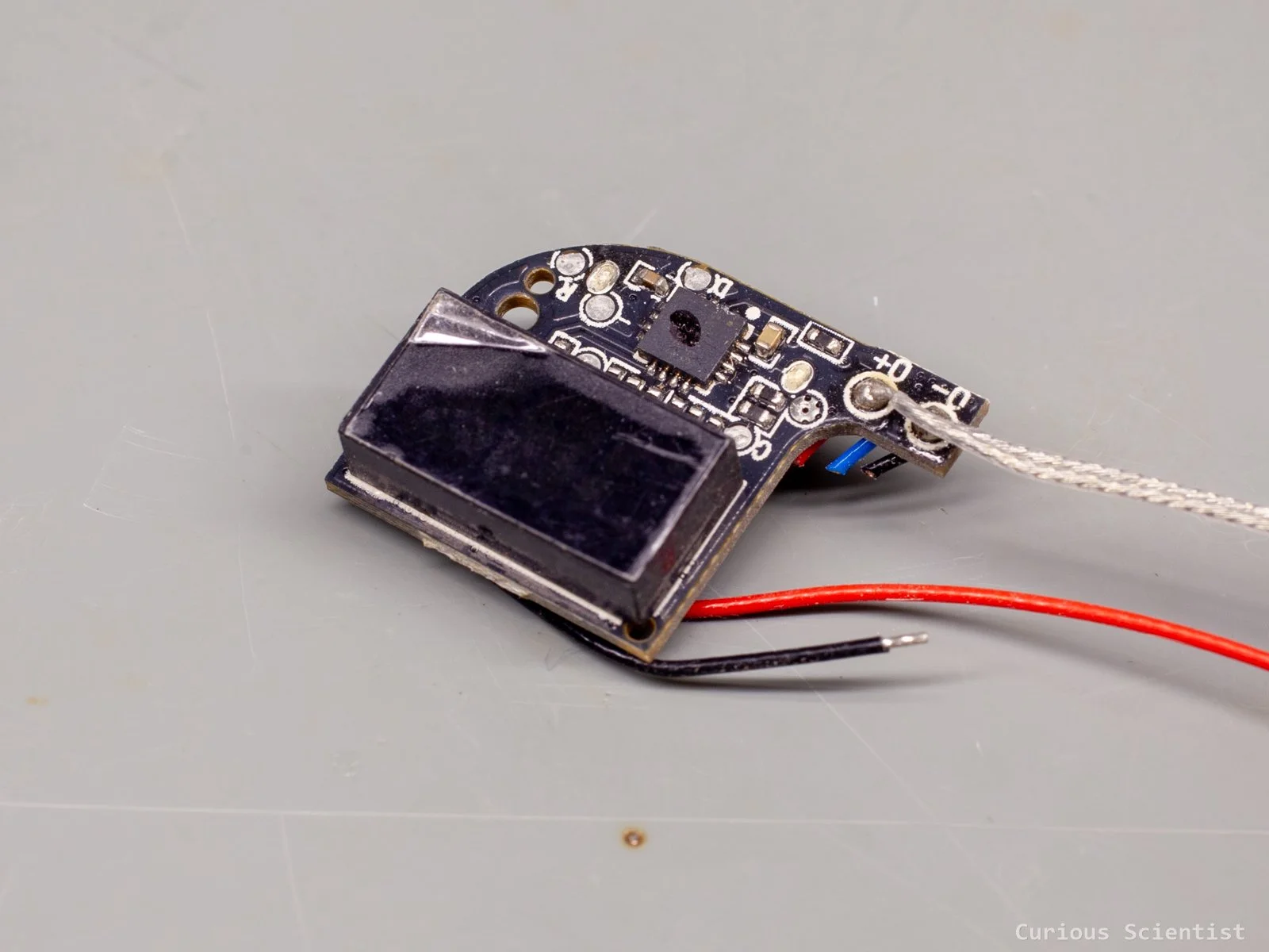
Recycled lithium charger with status display
Dual-shaft rotary encoder
This is not an extremely outstanding product, but it can be very useful in certain situations. In some projects, where I use rotary encoders to change values, it could come in handy if I could have a fine and a coarse adjustment possibility. Sure, it can be done with a single rotary encoder by some software tricks and so on. But sometimes we want a more mechanical approach because it feels better or safer.
So, this encoder has two shafts: an inner and an outer one. Each shafts have their knurled ring that makes the adjustment easier, and it also makes the encoder look better. The encoder also has a switch, so actually it has three options embedded: two encoders and a switch. It has 8 pins: 3-3 for each encoder (CLK, DT, GND) and two for the switch (IN, OUT). The only issue with the pin arrangements is that 5 pins are on the same side of the encoder, of which two pairs are “overlapping”, so it is not possible to use this kind of encoder in a breadboard. But one can easily fabricate a breakout board made of perfboard, or make a custom PCB for it.
I created a super simple demo code for it for Arduino Nano. The user can increase the numbers on a small OLED display using the encoder. The top ring allows a finer, and the bottom ring allows a coarser adjustment. The project can be a good “drop-in sketch” for larger projects where a similar encoder should be treated.
Soon, I will release a PCB for these encoders to make it easier to plug them into breadboards and circuit boards.
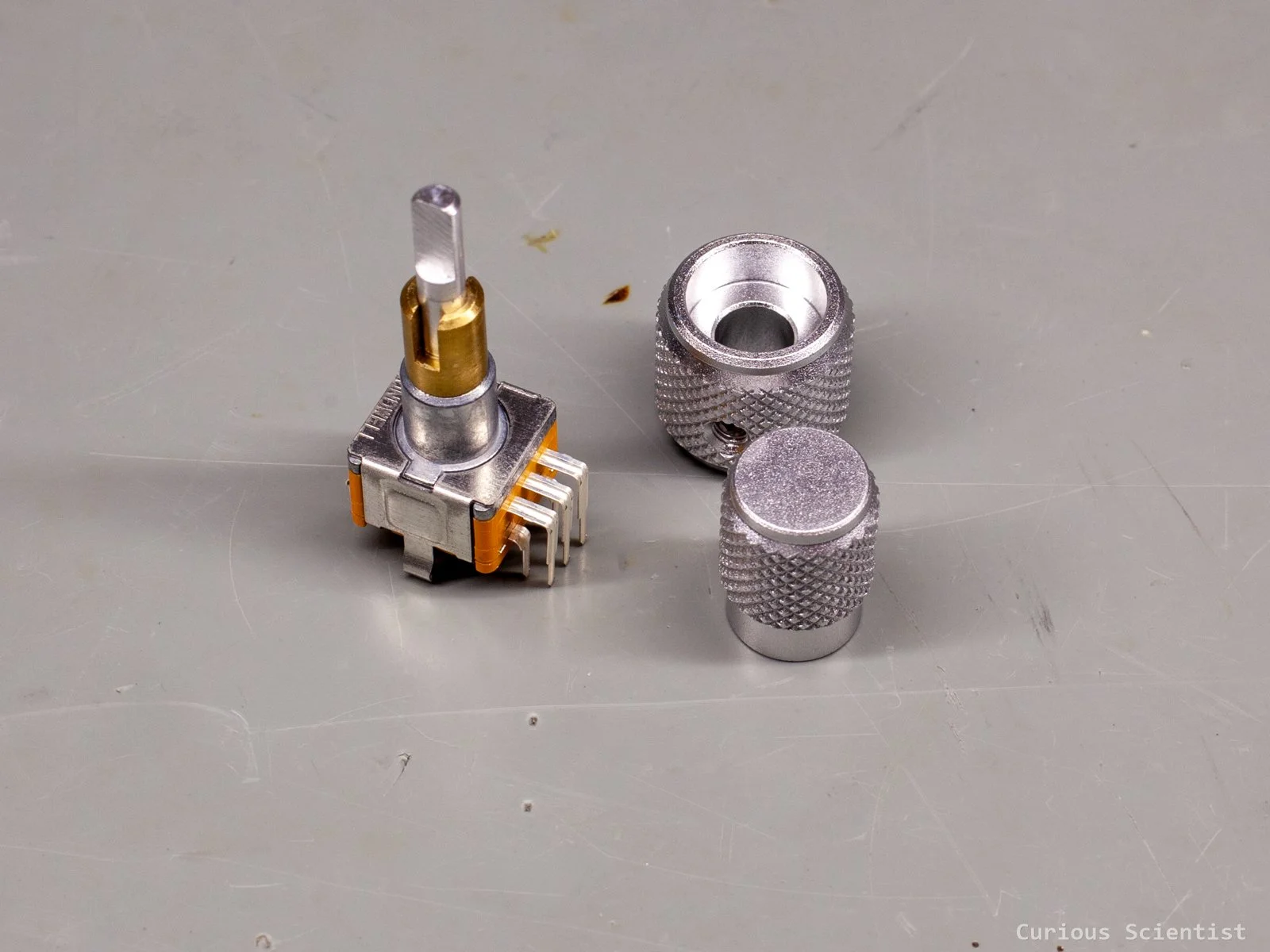
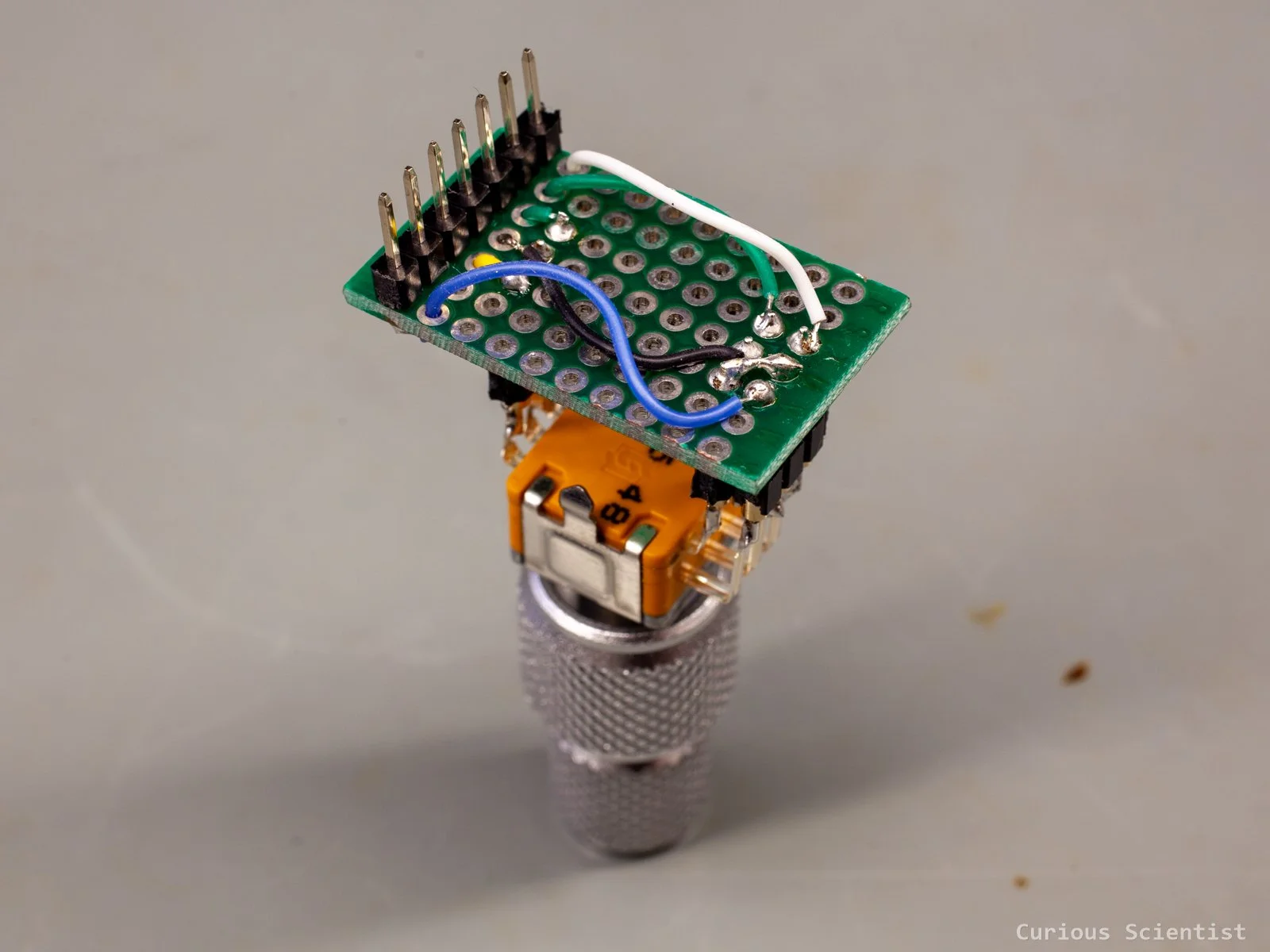
MagnTek MT6701 Differential Hall Magnetic Encoder
You might well know the AS5600 magnetic encoder, and maybe you know about it from me because I have several videos on it, and one of the most popular AS5600 videos on YouTube is mine.
This encoder is fairly similar, but it comes with more features! It has the same basic principles as the AS5600. Inside the chip, there are four Hall-effect sensors distributed at 90° apart. The chip is used with a special magnet that is radially (or diametrically) magnetised, so its south and north are not the top and the bottom of the magnet, but one half and the other. When the magnet is placed over the chip, the four Hall sensors feel different magnetic fields. The resulting output signal of the four Hall sensors together is converted to an angle which represents the position of the magnet.
The output signal, depending on the used communication protocol, can be a 14-bit binary code (I2C and SSI), PWM signal, analogue voltage, ABZ (typical encoder output: A-phase, B-phase and index signal) signal, or UVW signal.
In addition to the typical encoder operation, the encoder can also be used as a push button. The chip is prepared to be able to handle and interpret the different distances between the encoder chip and the magnet. The chip has a built-in function for this, and one can program a Z-threshold which can be used to interpret the distance changes as a button press. This is useful when the chip is used in encoders. The chip can both read the rotation of the encoder knob and the press of the knob, too! Unfortunately, the chip on this module does not support this option, but I am working on a solution.
I will also soon release a very detailed review article of this encoder with some cool use cases!
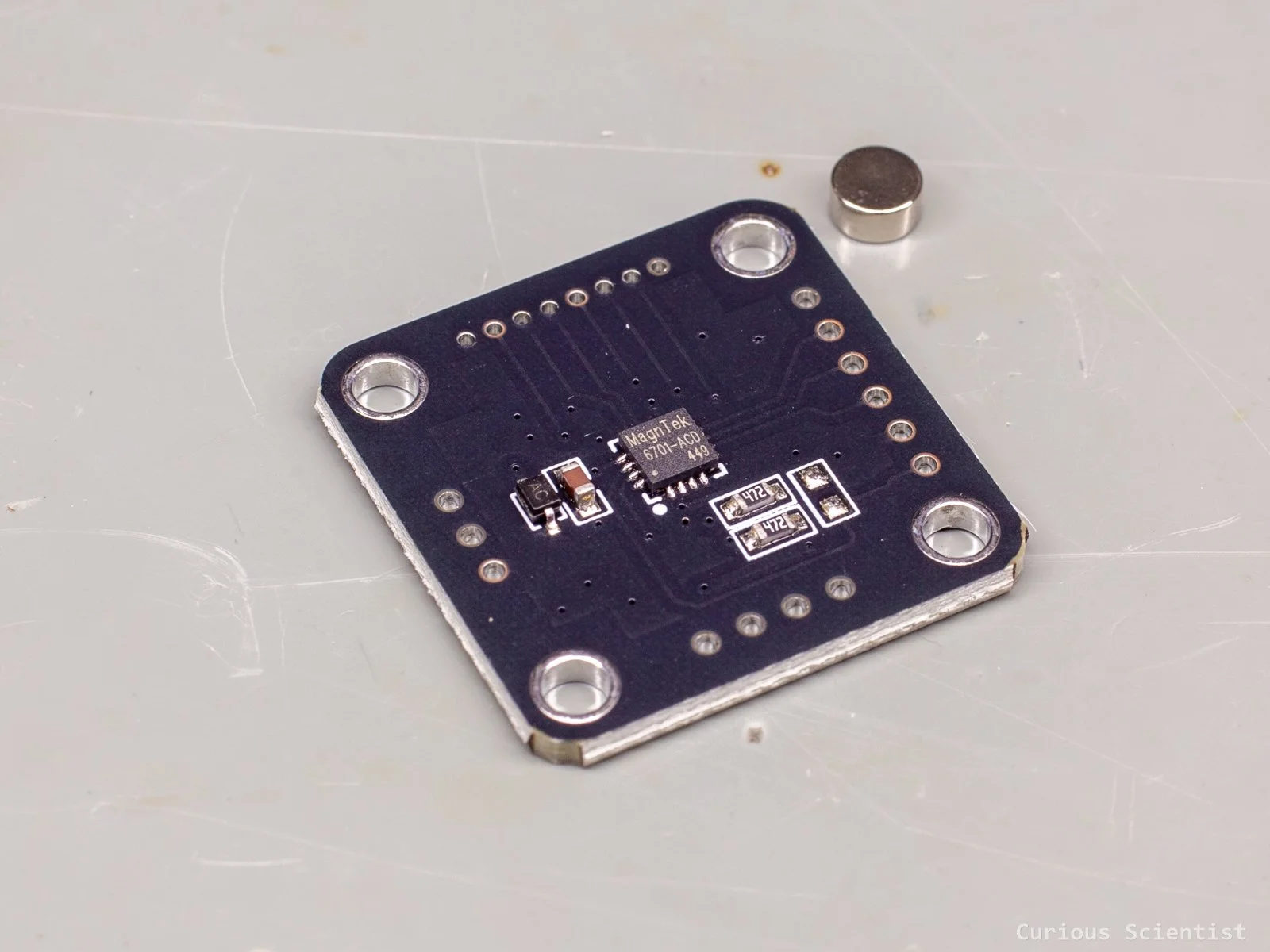
MT6701 -almost perfect- magnetic encoder
SMC05 stepper motor/servo motor controller
This device allows you to generate driving signals for stepper motors or servo motors. I test and demonstrate the product with a stepper motor, so I will focus on the stepper motor-related operation. As I said, the device is a signal generator, so it will still need a stepper motor driver that interprets the driving signals (STEP, DIR, ENABLE) and powers the stepper motor. In my demo, I use it with a TB6600 stepper motor driver and a NEMA23 stepper motor that drives a ballscrew-based linear actuator.
In my opinion, this is a perfect device for those who want to operate a simple stepper motor-based mechanism without involving microcontrollers and programming. A typical approach would be to use an Arduino Nano, program it using the AccelStepper library and then let it do its thing. But, for simple mechanisms, this could be too much extra work, and people might get discouraged. So, with this device, we can program simple operations and drive the stepper motor accordingly.
The device has a 1.8” colour display that allows the user to configure the device and the program that drives the stepper motor. It comes with 20 pre-programmed motion and behaviour patterns. One can drive the motor continuously while a button (FWD or REV) is kept pressed or until it is pressed again. One can set a certain number of pulses that the motor should travel, and this can even be done in an oscillating manner so that the motor rotates back and forth. We can even add up to 4 limit switches to the system and make the motor travel between them. The list is long, and I would not spend hours explaining them. Instead, I warmly recommend reading the datasheet where all these patterns are explained.
The device should be powered with voltages between 12 V and 24 V. If you don’t have a power supply around, but you have a USB-PD adapter, then you could get the previously introduced power supply circuit and use it for powering this module. The supplied 24 V is available on the output side of the device. Ideally, this 24 V output should be used to power the external devices such as the stepper motor driver, the limit switches or other peripherals. Just make sure that the power supply can provide enough current!
As I mentioned, it is possible to add up to 4 limit switches to the controller. They should be NPN normally open switches, and they should be able to tolerate 24 V. Typically, proximity switches are preferred. According to their cable colour coding, the brown wire should be connected to the 24 V positive supply line, the blue wire should go to ground (0V), and the black wire should go to one of the limit interfaces (X1-X4).
We can also add external buttons for RUN, DIR and STOP functions. They should also be 24V-compatible. Finally, there are four output channels O1-O4 which can be used to drive indicator lights, solenoid valves, etc.
The main display shows the selected program and the status of the operation. Speed, number of pulses, outputs, limit switches, everything can be accessed from the display. The buttons on the left are self-explanatory. Forward, reverse, set, exit and confirm. On the right side, the rotary encoder is used for navigation or modifying values, and the button under it is the start/stop button.
We can enter the menu with the SET button. This brings us to a menu with 3 items. The SYSTEM allows us to configure the controller, the MOTOR allows us to adjust the motor parameters, and the ACTION menu is where we can select a program and adjust its parameters.
Chapter 3 of the datasheet describes each mode and parameter very clearly.
With a dedicated USB-to-TTL module, which I don’t have, one can even connect the device to a computer. This allows communication and update functions. The manufacturer provides the communication protocol in the datasheet, so one can develop custom software for it that sends the required commands and parameters to the device. Furthermore, one can get a Bluetooth module for this controller and control it via an app on a mobile phone.
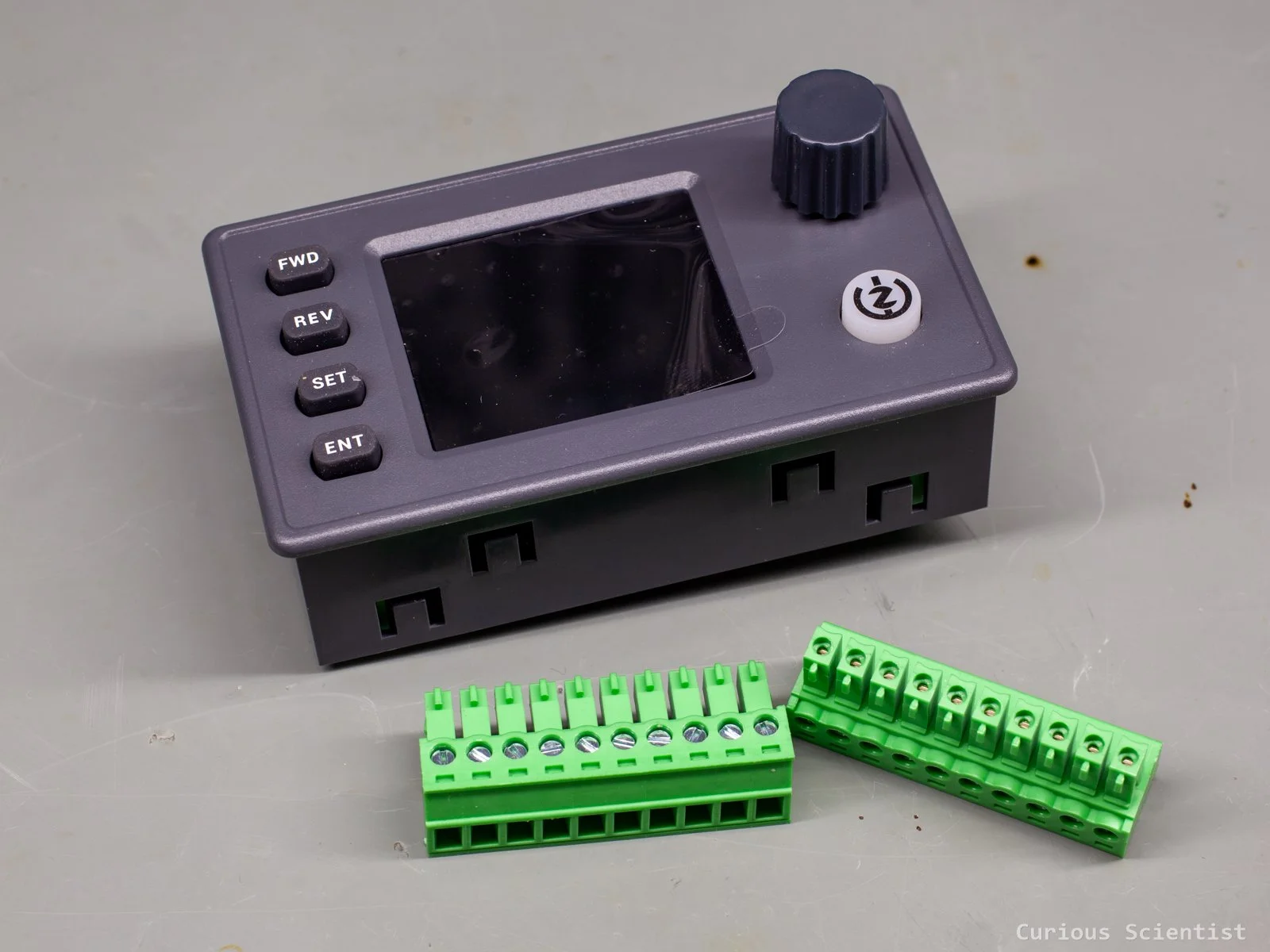
SMC05 stepper motor controller with its screw terminals
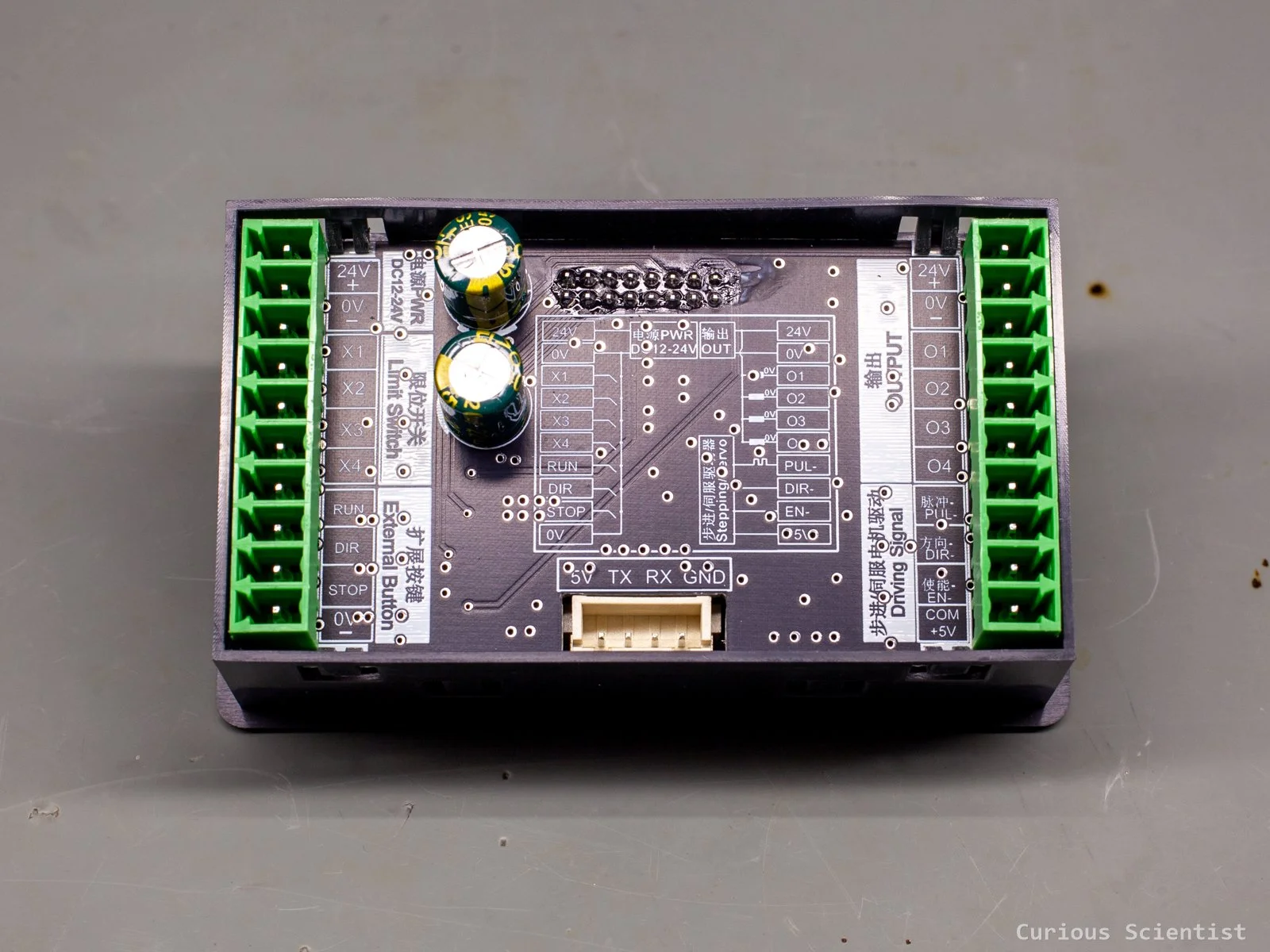
SMC05 stepper motor controller rear panel with all the connections and descriptions