MT6701 - A potentially better (than the AS5600) magnetic encoder
Recently, I have ordered a bunch of AliExpress gadgets, and this encoder board was among them. This is a great magnetic absolute encoder with a lot of features, so in this article I show you the encoder and some relevant project ideas. Similar to the well-known AS5600 magnetic encoder, this is also one. However, this chip packs many more features, such as different output signals, a push-button function, and a higher 14-bit resolution.
Introduction
The MT6701 magnetic encoder is based on the exact same principles as the AS5600. First of all, the chip requires a diametrically magnetised magnet that should be held between 0.5 mm and 2.0 mm above the surface of the chip. The recommended magnet size is 6.0 mm diameter and 2.5 mm height (thickness). This is very important because the chip only reports the correct values if it senses the correct changes in the magnetic field. The way it senses the magnetic field is relatively simple. Inside the chip, there are four Hall sensors at the four corners. As the magnet is rotated over the chip, the four Hall sensors feel different magnetic fields. The net output of the four sensors’ signals determines the angle of the magnet. The chip then reports this 0° to 360° angle in several different channels: I2C, SSI, UVW, analogue output, PWM output, ABZ output. It can measure up to 55000 RPM rotation speed. The chip operates between 3.3 V and 5 V, so it can work with both “older” Arduino boards and newer, for example, ESP32 boards. It uses around 10-14 mA, so it is not exactly a low-power device, but when monitoring motors, low power is probably not an issue anyway.
MT6701-ACD development board with a diametrically magnetized magnet
Analogue output
The chip provides a rail-to-rail linear output that mirrors the 0-360° encoder position. 0° is the lowest voltage and 360° is the highest voltage. The chip has a built-in 12-bit DAC that generates the corresponding output voltage. The user can even program upper and lower clamp points to limit the output voltage. The default is 0% and 100%, so the device outputs the full rail-to-rail range, but a 10% - 90% clamp can be introduced, which limits the voltage between 0.5 V and 4.5 V in the case of a 5 V supply voltage. Due to the clamping, a certain range of the measured angles won’t be accessible. When using a 5 V supply voltage, 0-30° (A_Start, signal clamped LOW) and 330-360° (A_Stop, signal clamped HIGH) angles will “disappear” because they are within the clamped region.
I just tested the normal operation mode of the analogue output. I used a multimeter and measured the output of the chip. It produced a stable output, and the voltage seemed to scale with the angles well. I measured the output voltages at four positions ~90° apart from each other and plotted the output voltage vs. angle points. The fitted line lies on the points perfectly, so the voltage-angle correlation is as linear as it can be.
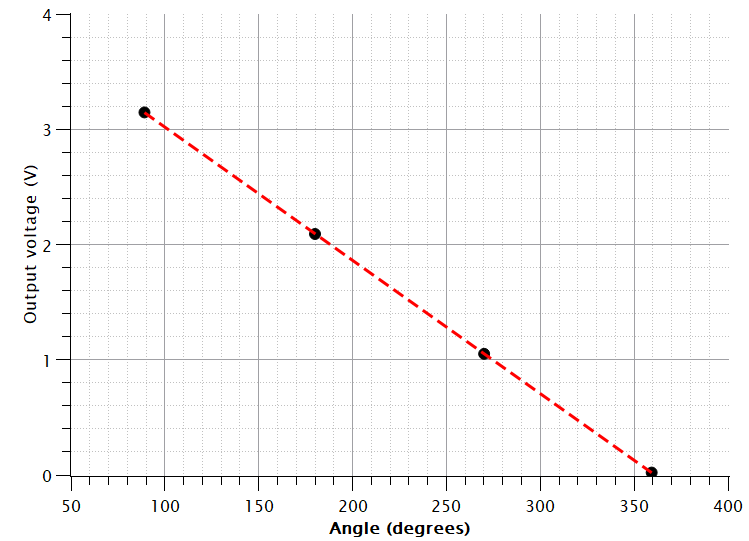
Voltage-angle points and a perfectly fitting linear fitting
PWM output
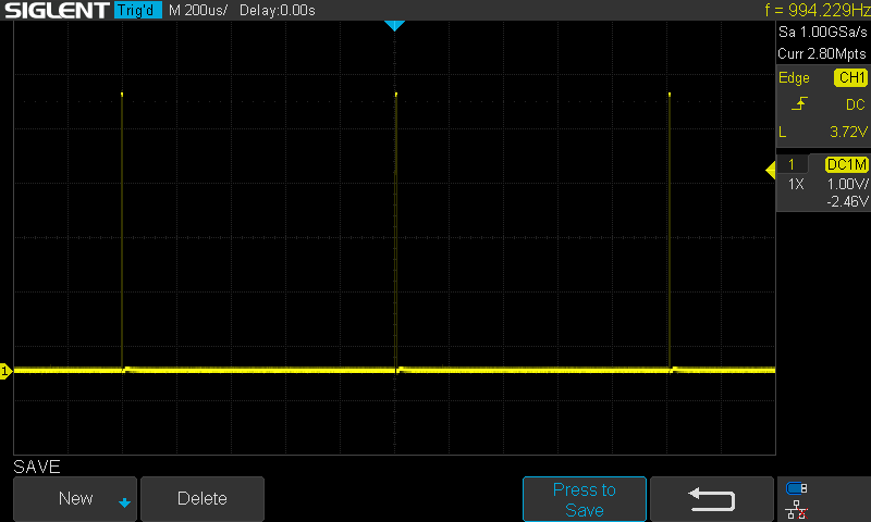
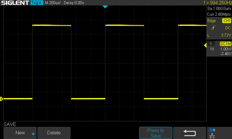
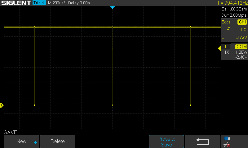
Apart from an analogue output, the device can also generate a PWM output on the same pin. The data is represented with 12-bit resolution, and a frame contains 4119 PWM clock periods. The signal consists of a 16-clock-period HIGH signal, then 4095 PWM pulses and finally, 8 clock periods of LOW signal. The length of the frame can be adjusted: it can be 994.4 Hz or 497.2 Hz (1/t = frequency). One should keep in mind that the chip must be reprogrammed for this operating mode. By default, the chip provides an analogue output.
ABZ output
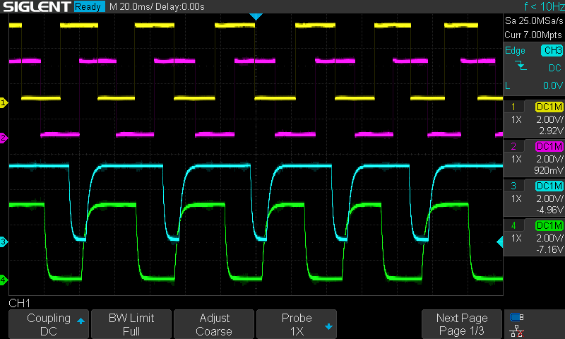
This output is similar to the output of regular optical or mechanical encoders. A and B signals produce identical but phase-shifted pulses, depending on the direction of the rotation, and Z produces a pulse for every rotation (indexing signal). So, while A and B can help to track the rotation direction and speed, Z helps to keep track of the accumulated number of turns. The resolution of the ABZ function can be programmed between 1 and 1024 PPR. This allows the chip to become a direct replacement for other types of encoders without the need to change anything in the signal processing of the new sensor.
I reprogrammed the chip to provide 24 PPR because that’s one of my mechanical encoder’s outputs. I tested it in both directions and with different speeds. I captured the signals using my 4-channel oscilloscope, and everything looked fine. As opposed to mechanical encoders, this output was free of any bouncing or other typical disturbances that we can experience when using a mechanical rotary encoder. One important note is that the MODE pin of the chip must be connected to GND, and since the A and B pins share the SDA and SCL lines, the I2C and SSI modes are unavailable while using the chip in ABZ output mode.
Of course, when the chip must be reconfigured, we just need to disconnect the MODE pin, so we regain the i2c or SSI mode of the chip, and we can communicate with it again.
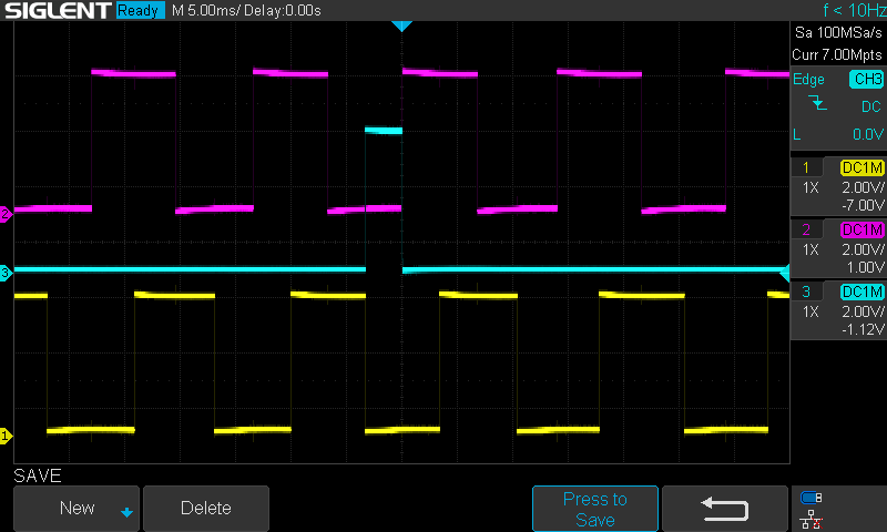
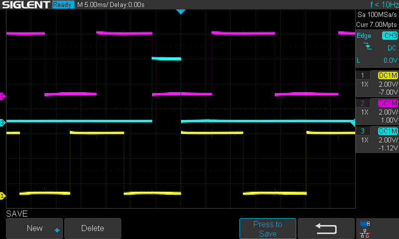
UVW output
The UVW output generates three identical pulses that are 120° out of phase with each other. This output is optimised for brushless motors; the signals emulate the three Hall-sensor signals that can be found in BLDC motors. So, this signal can be used for commutation feedback. We can program the UVW pole pairs in the encoder to match the motor’s characteristics. One important note is that the MODE pin of the chip must be connected to GND. This is somewhat against the information shown in the datasheet because the MODE pin should be used for switching between ABZ and I2C/SSI mode. But I could not get any UVW signals without connecting the MODE pin to GND. This automatically disables the I2C and SSI operation modes of the chip.
In UWV output mode, since the MODE pin has to be connected to GND, the encoder can’t communicate via I2C or SSI. However, ABZ mode is still outputting signals.
UVW (yellow, magenta, cyan) pulses
I2C output
It is a very typical i2c protocol. The 14-bit data is split between two registers: 0x03 and 0x04. The user must read the 0x03 register first, and then read the 0x04 register. The 0x03 register contains the angle value’s upper bits, and the 0x04 register contains the lower bits. Since the data is 14 bits, bits 0 and 1 are not used from the 0x04 register. Once the two registers’ data are combined together, a simple formula is used to calculate the angle in absolute degree units between 0-360°.
For example, on the captured package on the right side, we can see the following:
First, the MCU sends out the 0x06 value, which is the i2c address of the encoder. This initiates the communication.
Then, the MCU sends the 0x03 command to read the high byte of the angle register
Then, the MCU requests data from the 0x06 address
The encoder returns the content of the 0x03register: 1101 1001 → High byte
The encoder returns the content of the 0x04 register: 0001 1100 → Low byte
Then, we need to convert these two 8-bit values into a 14-bit value.
We place the high byte in an empty (all zeroes) 16-bit integer and shift it left by 6 positions.
1101 1001 << 6 = 0011 0110 0100 0000
We shift the low byte right by two positions and then combine the remaining bits with the previously created 16-bit integer
0011 0110 0100 0000 | (0001 1100 >> 2) = 0011 0110 0100 0111
We convert the above 16-bit (14-bit) number into a decimal number: 13895
We apply the formula from the datasheet: 13895/16384 × 360° = 305.31°
An I2C package
int16_t readMT6701RawAngle()
{
  Wire.beginTransmission(0x06);
  Wire.write(0x03);

  if (Wire.endTransmission(false) != 0)
  {
    return -1;
  }

  if (Wire.requestFrom(0x06, uint8_t(2)) != 2)
  {
    return -1;
  }

  const uint8_t highByte = Wire.read();
  const uint8_t lowByte  = Wire.read();

  return (uint16_t(highByte) << 6) | (lowByte >> 2);
}
SSI output
This is somewhat similar to SPI, but it is unidirectional. There are three signals, CSN, CLK and DO, and the communication is unidirectional only. The encoder sends data to the microcontroller, but the microcontroller does not send anything to the encoder. The angle is read out in a 24-bit package. When the microcontroller pulls the CSN pin LOW, the package can be read out according to the clock (CLK) pulses. The package contains 14 bits for the angle data, 4 bits for the magnetic field status and 6 bits of CRC code. The angle data is converted to degrees with the same formula as in the case of the i2c protocol. The magnetic status (bits 1 and 2) can have three values: normal, too weak and too strong. Plus, the third bit (bit 2) can be used for detecting a button press, and the fourth bit (bit 3) can be used to see if the status is normal or loss of track (internal tracking can not keep up with the changing magnetic angle).
A 24-bit package is shown on the right side.
The CS pin is pulled LOW, and the clock (CLK) starts generating the pulses. Each data bit should be captured at the falling edge of the CLK pulse.
Once the 24-bit package is completed, CS goes high.
We need to extract bit 0-13 which are the 14 bits of the angle data:
1111 1010 0111 1000 0001 1011
We simply convert the above binary data to decimal and convert it to degrees using the same formula we used in the i2c example:
16030/16384 × 360° = 352.22°
But the package has 10 further bits that we can use: 00 0001 1011
The next 4 bits are used for determining the magnet’s status: 00 00
The first two bits (Mg[1:0]) tell about the field strength. Zero means normal.
The third bit tells about the push button status. Zero means normal (no button press was detected).
The last bit tells about the tracking status of the magnet. Zero means normal (encoder can keep track of the magnet).
The final 6 bits (01 1011) are used for CRC. These are error detection bits.
First, the CRC polynomial in the datasheet is not a mathematical polynomial. It is just some engineering garbage language made for confusing people. The datasheet states the polynomial as x^6 + x + 1. This, in practice, means that we have a 7-bit binary, since the highest exponent is six, but machines like to count from zero, so there is an extra position, zero as well. Then, it also means that at the sixth bit (7th position), this binary value is one. Then, the x means that at the first bit (x^1) we also have a one, and finally at the zeroth bit (x^0 = 1) we also have one.
This becomes 1000011, which is the generator pattern. But in 6 bits (length of CRC), this remains 000011
Then, we need to go through every 18 bits of the remaining datastream and do the following:
Compare the incoming bit with the leftmost bit of the current CRC (1 XOR 0 = 1)
Shift the CRC left by one position 000000 → 000000
When the comparison results in 1, XOR the shifted CRC with 000011 (000000 XOR 000011 = 000011)
When it is zero, don’t do anything
When we finish this shifting for all 18 bits, we should have 011011 as the result. This is exactly what we got from the controller as the CRC number.
An SSI package
int16_t readMT6701SSIRawAngle(
    uint8_t &fieldStatus,
    bool &pushDetected,
    bool &lossOfTrack,
    uint8_t &receivedCRC,
    uint8_t &calculatedCRC,
    bool &crcOK,
    uint32_t &rawFrame)
{

  digitalWrite(TFT_CS, HIGH);

  SPI.beginTransaction(SPISettings(500000UL, MSBFIRST, SPI_MODE1));

  digitalWrite(MT6701_SSI_CS, LOW);
  delayMicroseconds(2);

  rawFrame  = uint32_t(SPI.transfer(0xFF)) << 16;
  rawFrame |= uint32_t(SPI.transfer(0xFF)) << 8;
  rawFrame |= uint32_t(SPI.transfer(0xFF));

  delayMicroseconds(1);
  digitalWrite(MT6701_SSI_CS, HIGH);

  SPI.endTransaction();

  receivedCRC = rawFrame & 0x3F;

  const uint32_t angleAndStatus = rawFrame >> 6;

  calculatedCRC = calculateMT6701CRC6(angleAndStatus);
  crcOK = receivedCRC == calculatedCRC;

  const uint8_t status = (rawFrame >> 6) & 0x0F;

  fieldStatus = status & 0x03;
  pushDetected = (status & 0x04) != 0;
  lossOfTrack = (status & 0x08) != 0;

  if (MT6701_SSI_VALIDATE_CRC && !crcOK)
  {
    return -1;
  }

  return (rawFrame >> 10) & 0x3FFF;
}
Applications
Rotary encoder with push-button function
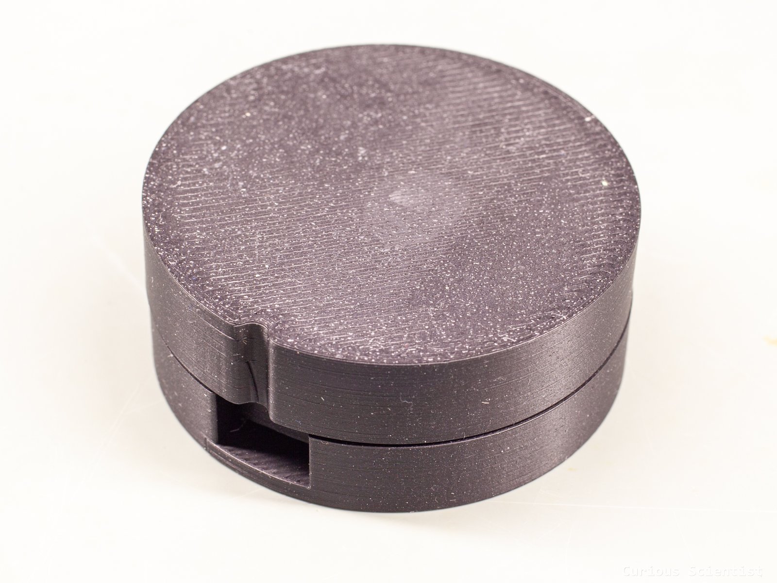
This one took several iterations, and the first board with the QFN16 chip on it did not even allow me to fully utilise it. I wanted to focus on the push-button function of the encoder when I designed the 3D-printed body for it.
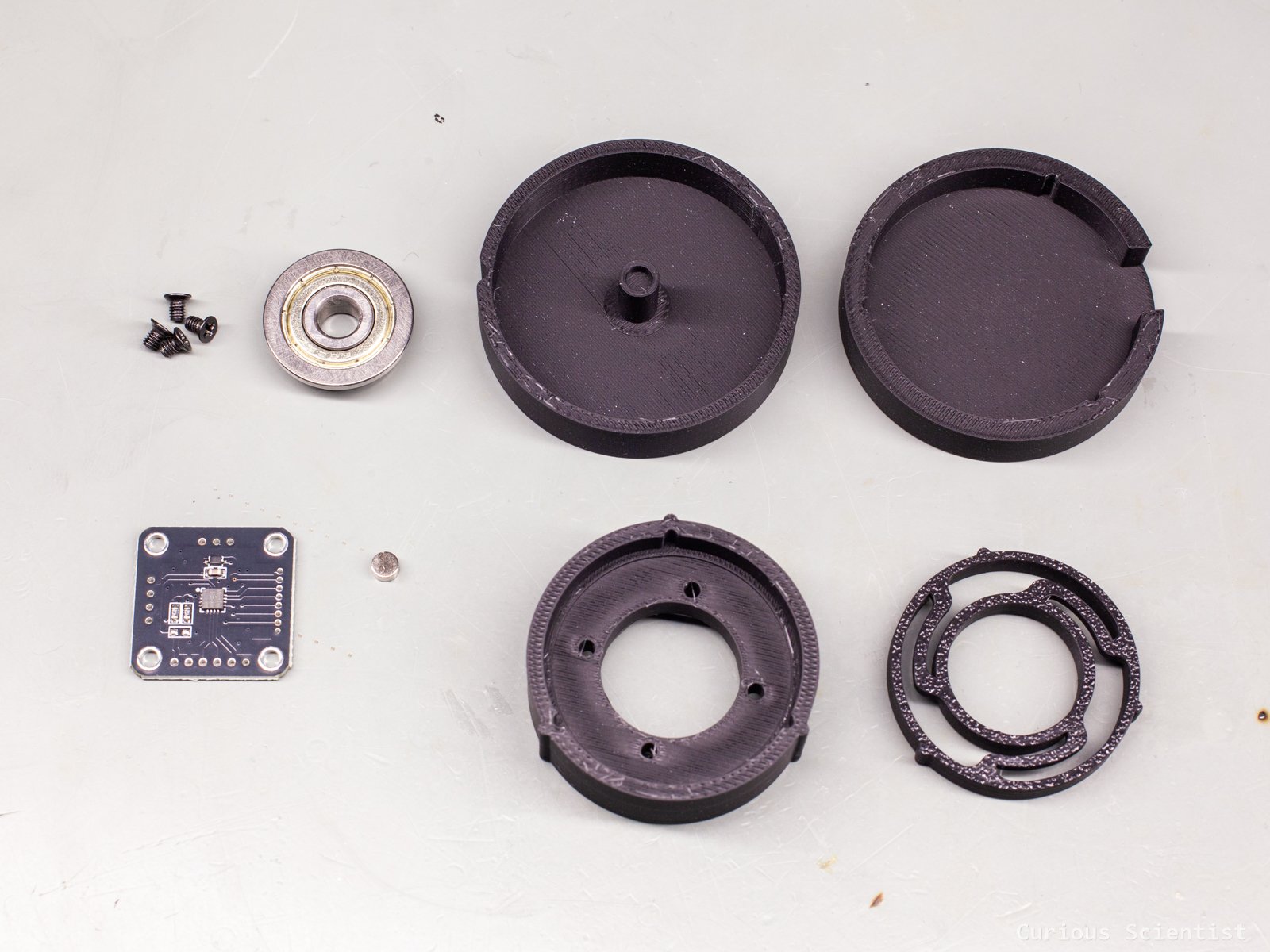
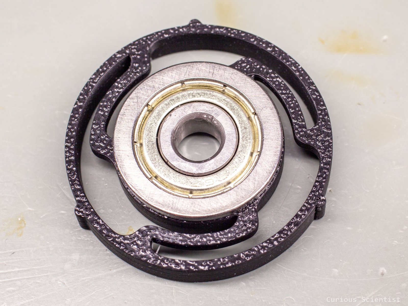
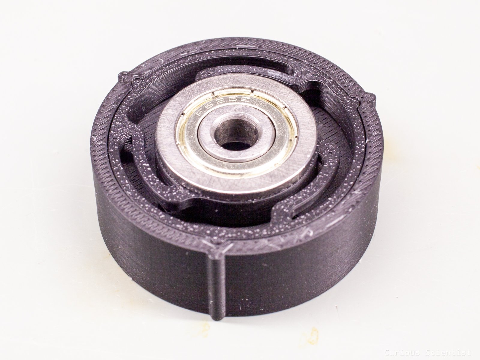
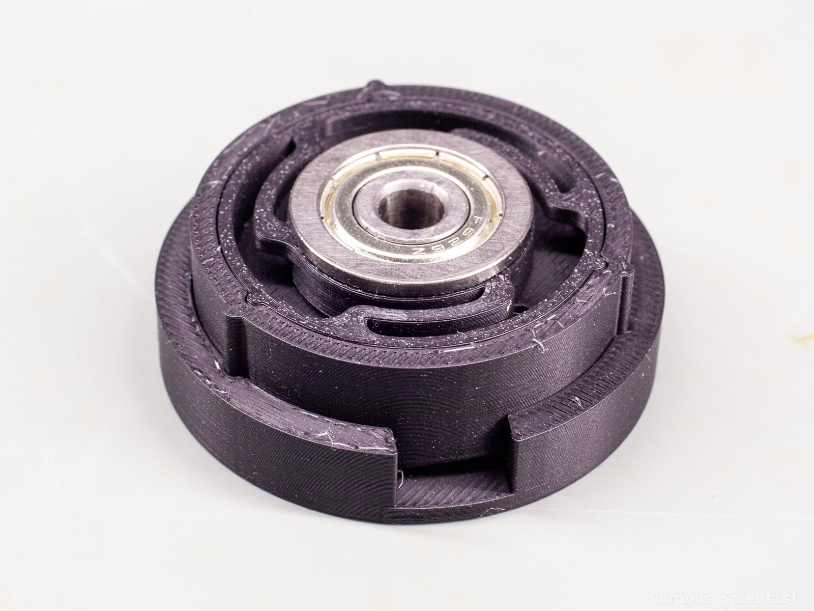
So, the chip’s push-button function is based on the idea that the chip can detect and interpret the magnet’s vertical displacement. If this displacement is well-controlled (fast and straight enough), the chip can send a push signal either via the SSI package or via the dedicated push pin (5) of the chip. To make this vertical displacement possible, I designed a smart mechanism for the knob. I drew a torsion spring that can be slid into the main body of the knob, and it supports a flange bearing in its centre. The suspension of the flange bearing has a roughly 1 mm play downwards, which, according to the datasheet, should be enough. The suspension is mechanically stopped by the main body of the encoder, so the user can not push the knob so much that the magnet would hit the encoder chip. The torsion spring’s body received three little ridges that slide in the three corresponding slots in the main body of the encoder. This allows a tight fit, and it hinders the suspension’s rotation when the knob is rotated.
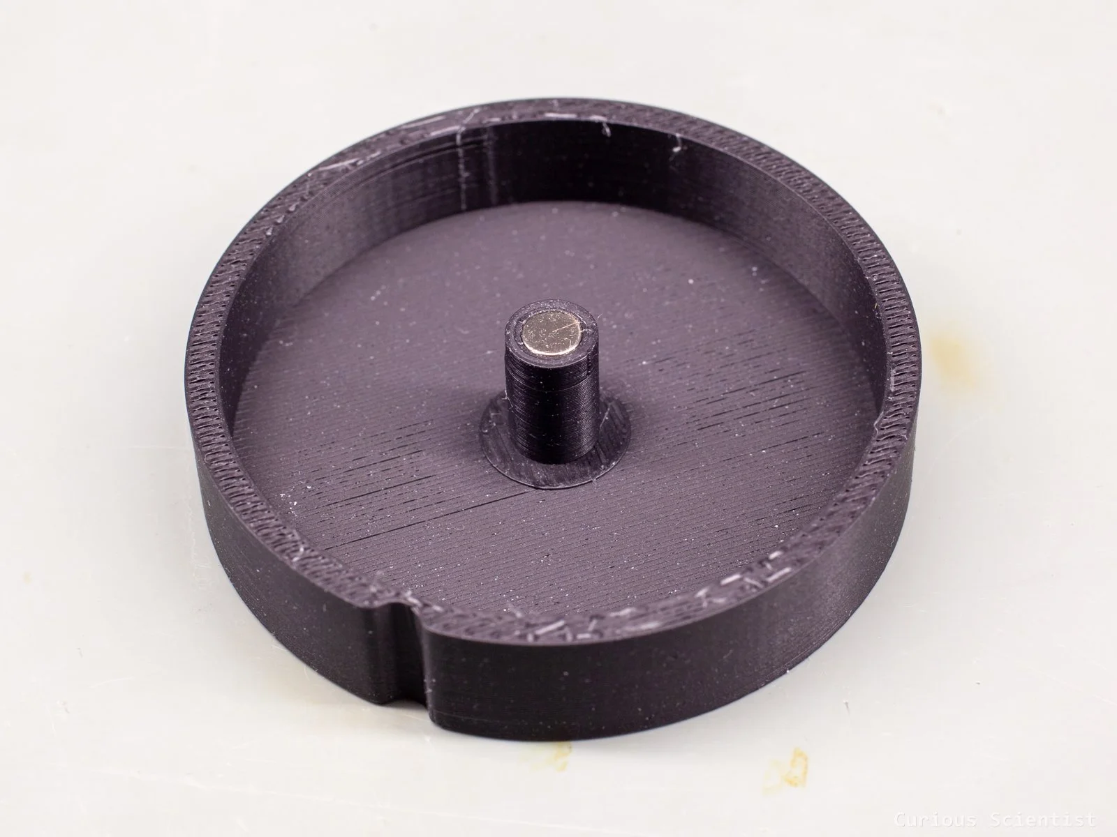
The knob is just a regular-looking knob, and on its inside there is a column with a slot for the magnet in it. It is tightly holding the magnet, but a drop of glue won’t hurt when installing the magnet in the slot. The columnar part is held by the flange bearing that sits in the torsion spring.
The bottom of the whole construction also received a tight-fitting cup. This makes the whole knob look smooth, and it protects the bottom of the encoder’s PCB. I used the same ridge-slot idea to fit the cup to the main body of the encoder that I used for the torsion spring. It allows a snug, but easy-to-disassemble fit.
So, despite my efforts and after trying different chips (QFN-16 and SOP-8), I was unable to make the button function work. Big bummer. I specifically designed the 3D-printable housing to utilise the push-button function, but it seems that the chip manufacturer is lying, or intentionally holding back certain information. I even sent them an email, but they did not bother replying.
Stepper motor encoder
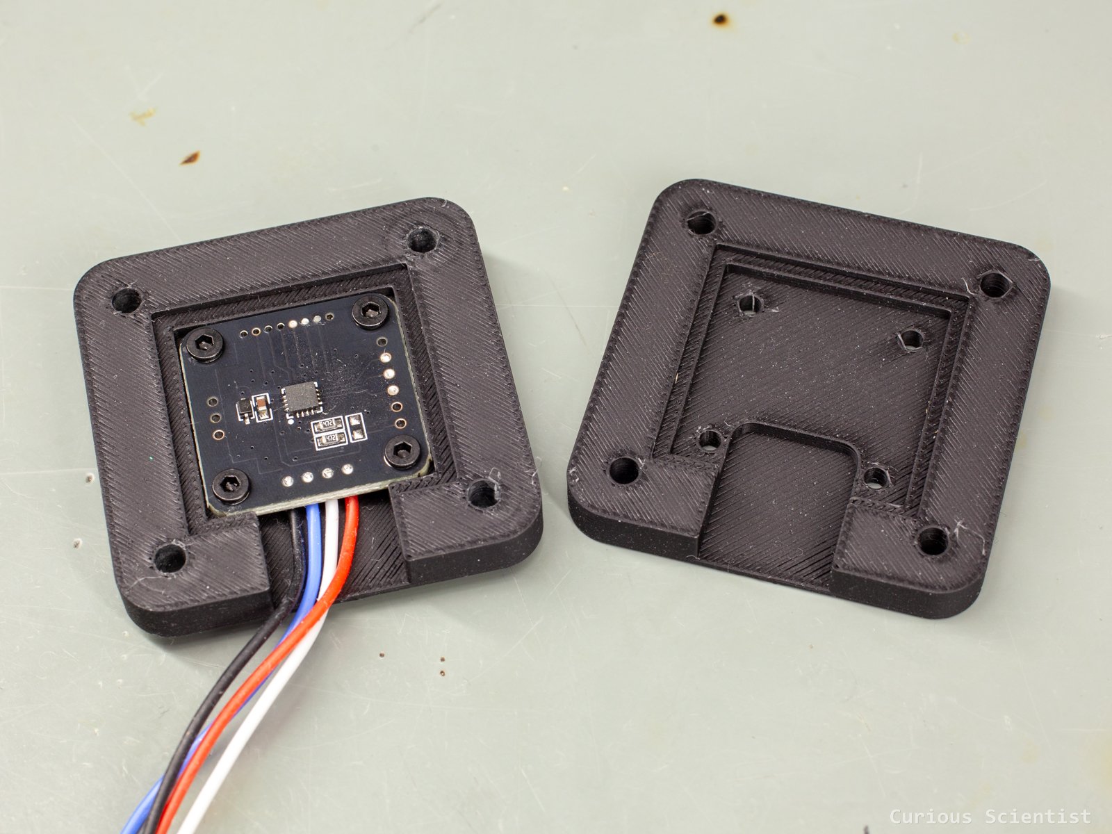
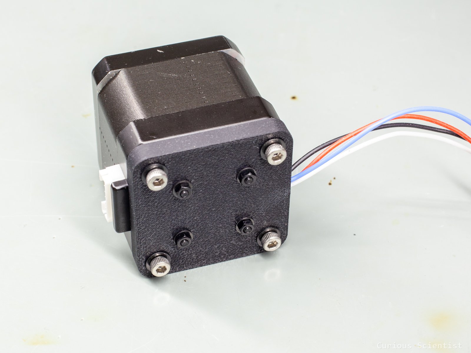
This is similar to what I did with the AS5600 encoder. I designed and 3D printed an attachment that accommodates the sensor’s PCB and fits the back of a NEMA17 stepper motor.
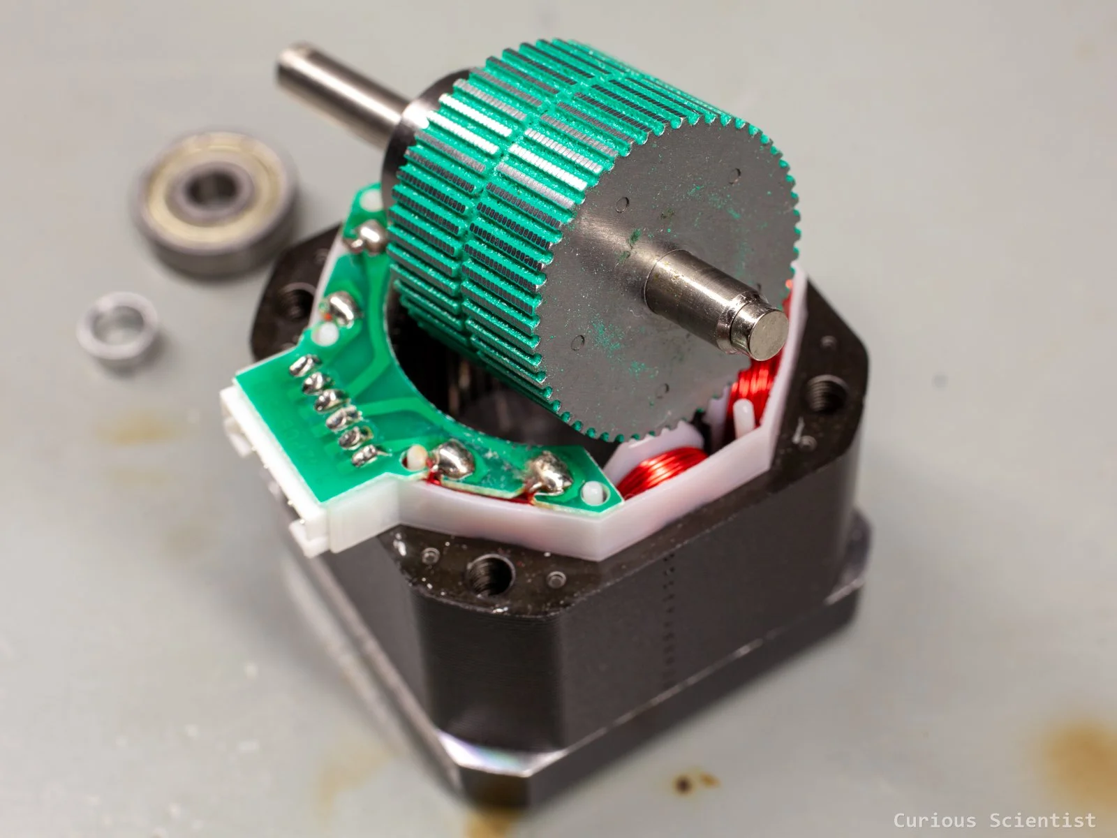
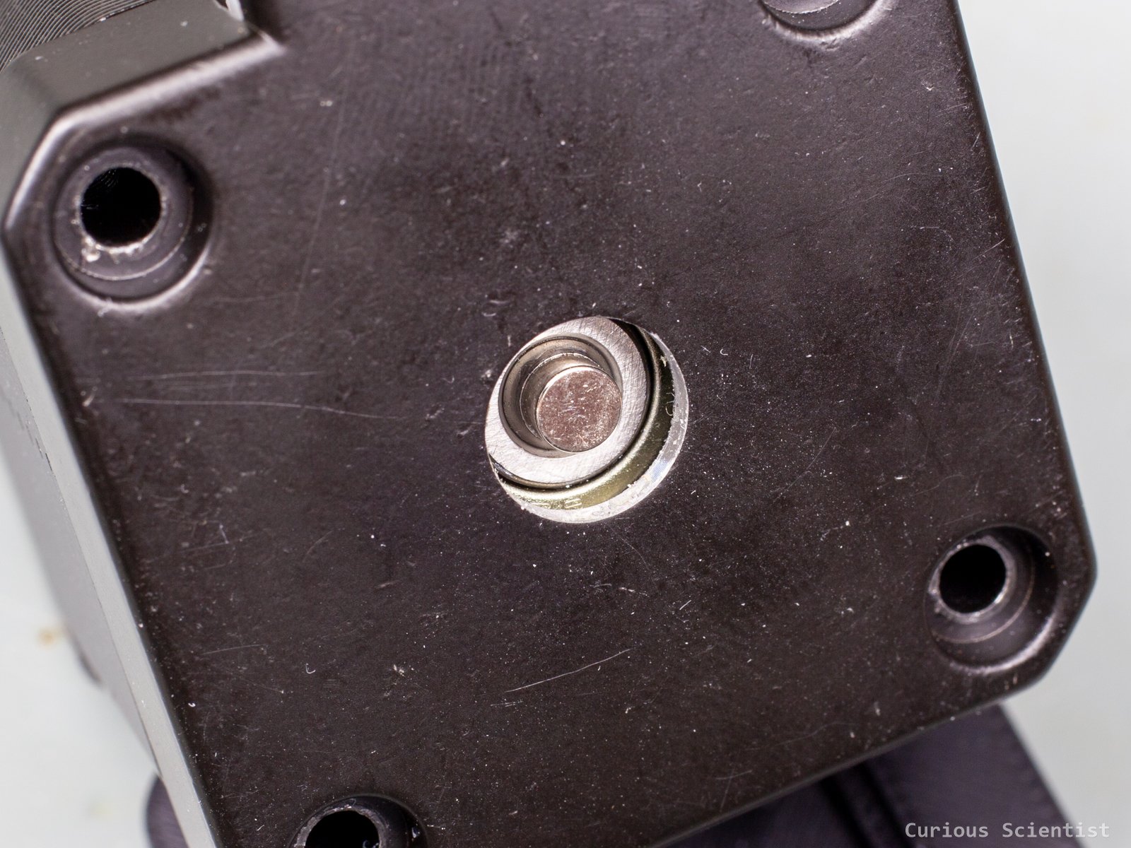
First, I disassembled the stepper motor and glued the magnet on the shaft. This was a bit difficult because of the diametrically magnetized magnet. It always wanted to fly away. The glueing was not simple either. I put a drop of super glue on the shaft, then I removed part of it and let it cure just a little bit. Then I put the magnet on the shaft and kept it pressed against the shaft for a while to ensure adhesion. Oh, and of course, I degreased both the shaft and the magnet to allow good adhesion for the glue.
Then I reassembled the stepper motor. I mounted the sensor PCB in the 3D-printed attachment. I just used four M2 bolts with nuts and washers. The attachment was then mounted on the stepper motor. I could not reuse the stepper motor’s four M3 bolts, so I had to find new, longer (40mm) ones. The original bolts were precisely chosen for the stepper motor. I tightly screwed the bolts into the motor, and the setup was done.
If you found this content useful, please consider joining my YouTube channel’s membership or leaving a donation.
Also, please consider using my affiliate links when buying relevant gadgets.
MT6701 vs. AS5600 Comparison
| Property | AS5600 | MT6701 |
|---|---|---|
| Absolute resolution | 12-bit: 4096 positions per revolution, about 0.0879° per count. | 14-bit: 16384 positions per revolution, about 0.0220° per count. |
| Angle range | 0–360°, with programmable start and stop range. | 0–360°, with programmable zero and analog/PWM start and stop angles. |
| I²C | Yes. Fixed address 0x36. | Yes. Default address 0x06, optionally programmable to 0x46. |
| SSI | No. | Yes. 24-bit frame with angle, status, and CRC. |
| CRC protection | No CRC on the normal I²C angle reading. | SSI includes a 6-bit CRC. |
| Analog output | 12-bit ratiometric analog output. | 12-bit ratiometric analog output with programmable range. |
| PWM output | Yes. Several selectable frequencies. | Yes. Approximately 497.2 or 994.4 Hz. |
| AB quadrature | No. | Yes. Programmable from 1 to 1024 PPR. |
| Index / Z output | No. | Yes. Programmable position and pulse width. |
| UVW commutation | No. | Yes. Programmable from 1 to 16 pole pairs. |
| Differential ABZ | No. | Available on the QFN-16 version as −A, −B, and −Z. |
| Direction setting | Direction selected using a hardware pin. | Direction selected using an EEPROM setting. |
| Magnet diagnostics | Magnet detected, too strong, or too weak; also provides AGC and magnitude data. | Normal, too strong, too weak, push detected, and loss of track through SSI status. |
| Contactless pushbutton | No dedicated push function. | Dedicated PUSH output and SSI push-status bit. |
| Typical accuracy | Approximately ±1° under specified conditions. | Approximately ±1° typical and ±1.5° maximum. |
| Response | Approximately 150 µs sampling period, with configurable filtering. | Approximately 5 µs propagation delay at constant speed. |
| Maximum speed | No explicit maximum RPM stated in the compared datasheet. | Up to 55,000 RPM. |
| Supply current | Approximately 6.5 mA in normal mode. | Approximately 10 mA typical. |
| Low-power modes | Yes. | No comparable programmable low-power mode documented. |
| Supply voltage | 5 V operation or direct 3.3 V operation, depending on wiring. | 3.0–5.5 V. EEPROM programming requires more than 4.5 V. |
| Nonvolatile memory | OTP memory with limited permanent programming cycles. | Reprogrammable EEPROM through I²C. |
| Magnetic field range | Approximately 300–900 gauss. | Approximately 200–1000 gauss. |
| Typical air gap | Approximately 0.5–3 mm, depending on magnet geometry. | Approximately 0.5–2.0 mm. |
| Packages | SOIC-8. | SOP-8 or 3 × 3 mm QFN-16. |
| Operating temperature | −40°C to +125°C. | −40°C to +125°C. |