AS5600 magnetic position encoder
In this video I show you how to use the AS5600 magnetic position encoder. This is a very powerful chip for projects where you need a precise information about the position of a shaft. Therefore, it is extremely useful for stepper motor-related projects because you can use the sensor to directly measure the displacement of the shaft of the stepper motor. Its angular resolution is 0.08789°/bit, so if you use it with a stepper motor that has a 1.8° angular resolution, you can use the motor up to 3200 step/turn microstepping and still get decent numbers.
Here you can find the datasheet of the encoder if you need more information.
Schematics
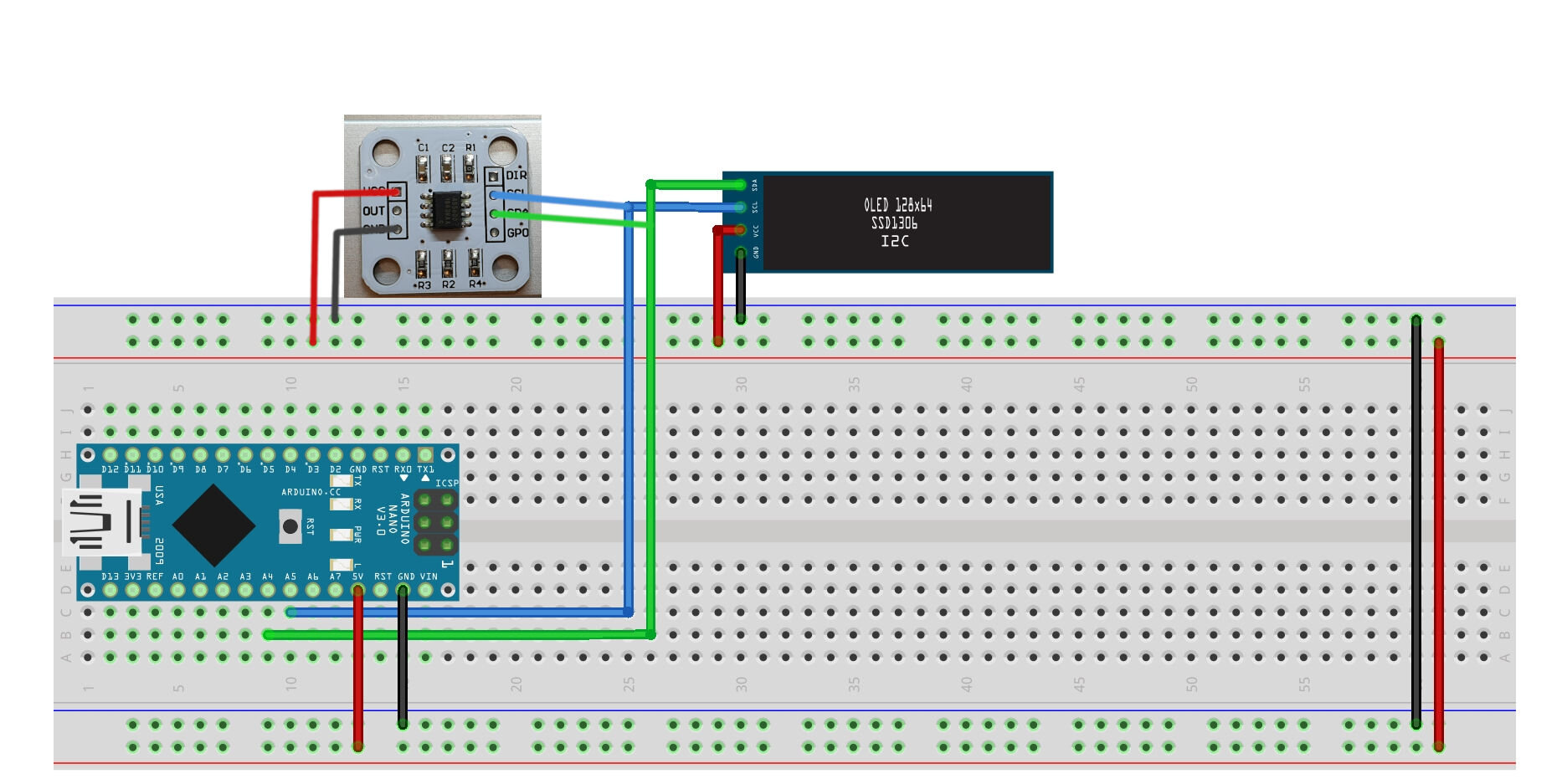
This example uses an Arduino Nano. Both the OLED display and the AS5600 encoder is connected to the Arduino via the i2C connection. On Nano, the i2C pins are the A4 (SDA - green) and A5 (SCL - blue). Both devices are connected to 5 V. Note: If you see issues with fluctuating values, connect the DIR pin to GND.
Arduino source code
#include <Wire.h> //This is for i2C
#include <SSD1306Ascii.h> //i2C OLED
#include <SSD1306AsciiWire.h> //i2C OLED

// i2C OLED
#define I2C_ADDRESS 0x3C
#define RST_PIN -1
SSD1306AsciiWire oled;
float OLEDTimer = 0; //Timer for the screen refresh
//I2C pins:
//STM32: SDA: PB7 SCL: PB6
//Arduino: SDA: A4 SCL: A5

//---------------------------------------------------------------------------
//Magnetic sensor things
int magnetStatus = 0; //value of the status register (MD, ML, MH)

int lowbyte; //raw angle 7:0
word highbyte; //raw angle 7:0 and 11:8
int rawAngle; //final raw angle
float degAngle; //raw angle in degrees (360/4096 * [value between 0-4095])

int quadrantNumber, previousquadrantNumber; //quadrant IDs
float numberofTurns = 0; //number of turns
float correctedAngle = 0; //tared angle - based on the startup value
float startAngle = 0; //starting angle
float totalAngle = 0; //total absolute angular displacement
float previoustotalAngle = 0; //for the display printing

void setup()
{
  Serial.begin(115200); //start serial - tip: don't use serial if you don't need it (speed considerations)
  Wire.begin(); //start i2C
	Wire.setClock(800000L); //fast clock

  checkMagnetPresence(); //check the magnet (blocks until magnet is found)

  ReadRawAngle(); //make a reading so the degAngle gets updated
  startAngle = degAngle; //update startAngle with degAngle - for taring

  //------------------------------------------------------------------------------
  //OLED part
  #if RST_PIN >= 0
  	oled.begin(&Adafruit128x32, I2C_ADDRESS, RST_PIN);
  #else // RST_PIN >= 0
  	oled.begin(&Adafruit128x32, I2C_ADDRESS);
  #endif // RST_PIN >= 0

	oled.setFont(Adafruit5x7);
	oled.clear(); //clear display
	oled.set2X(); //double-line font size - better to read it
  oled.println("Welcome!"); //print a welcome message
  oled.println("AS5600"); //print a welcome message
  delay(3000);
	OLEDTimer = millis(); //start the timer

}

void loop()
{
    ReadRawAngle(); //ask the value from the sensor
    correctAngle(); //tare the value
    checkQuadrant(); //check quadrant, check rotations, check absolute angular position
    refreshDisplay();
    //delay(100); //wait a little - adjust it for "better resolution"

}

void ReadRawAngle()
{
  //7:0 - bits
  Wire.beginTransmission(0x36); //connect to the sensor
  Wire.write(0x0D); //figure 21 - register map: Raw angle (7:0)
  Wire.endTransmission(); //end transmission
  Wire.requestFrom(0x36, 1); //request from the sensor

  while(Wire.available() == 0); //wait until it becomes available
  lowbyte = Wire.read(); //Reading the data after the request

  //11:8 - 4 bits
  Wire.beginTransmission(0x36);
  Wire.write(0x0C); //figure 21 - register map: Raw angle (11:8)
  Wire.endTransmission();
  Wire.requestFrom(0x36, 1);

  while(Wire.available() == 0);
  highbyte = Wire.read();

  //4 bits have to be shifted to its proper place as we want to build a 12-bit number
  highbyte = highbyte << 8; //shifting to left
  //What is happening here is the following: The variable is being shifted by 8 bits to the left:
  //Initial value: 00000000|00001111 (word = 16 bits or 2 bytes)
  //Left shifting by eight bits: 00001111|00000000 so, the high byte is filled in

  //Finally, we combine (bitwise OR) the two numbers:
  //High: 00001111|00000000
  //Low:  00000000|00001111
  //      -----------------
  //H|L:  00001111|00001111
  rawAngle = highbyte | lowbyte; //int is 16 bits (as well as the word)

  //We need to calculate the angle:
  //12 bit -> 4096 different levels: 360° is divided into 4096 equal parts:
  //360/4096 = 0.087890625
  //Multiply the output of the encoder with 0.087890625
  degAngle = rawAngle * 0.087890625;

  //Serial.print("Deg angle: ");
  //Serial.println(degAngle, 2); //absolute position of the encoder within the 0-360 circle

}

void correctAngle()
{
  //recalculate angle
  correctedAngle = degAngle - startAngle; //this tares the position

  if(correctedAngle < 0) //if the calculated angle is negative, we need to "normalize" it
  {
  correctedAngle = correctedAngle + 360; //correction for negative numbers (i.e. -15 becomes +345)
  }
  else
  {
    //do nothing
  }
  //Serial.print("Corrected angle: ");
  //Serial.println(correctedAngle, 2); //print the corrected/tared angle
}

void checkQuadrant()
{
  /*
  //Quadrants:
  4  |  1
  ---|---
  3  |  2
  */

  //Quadrant 1
  if(correctedAngle >= 0 && correctedAngle <=90)
  {
    quadrantNumber = 1;
  }

  //Quadrant 2
  if(correctedAngle > 90 && correctedAngle <=180)
  {
    quadrantNumber = 2;
  }

  //Quadrant 3
  if(correctedAngle > 180 && correctedAngle <=270)
  {
    quadrantNumber = 3;
  }

  //Quadrant 4
  if(correctedAngle > 270 && correctedAngle <360)
  {
    quadrantNumber = 4;
  }
  //Serial.print("Quadrant: ");
  //Serial.println(quadrantNumber); //print our position "quadrant-wise"

  if(quadrantNumber != previousquadrantNumber) //if we changed quadrant
  {
    if(quadrantNumber == 1 && previousquadrantNumber == 4)
    {
      numberofTurns++; // 4 --> 1 transition: CW rotation
    }

    if(quadrantNumber == 4 && previousquadrantNumber == 1)
    {
      numberofTurns--; // 1 --> 4 transition: CCW rotation
    }
    //this could be done between every quadrants so one can count every 1/4th of transition

    previousquadrantNumber = quadrantNumber;  //update to the current quadrant

  }
  //Serial.print("Turns: ");
  //Serial.println(numberofTurns,0); //number of turns in absolute terms (can be negative which indicates CCW turns)

  //after we have the corrected angle and the turns, we can calculate the total absolute position
  totalAngle = (numberofTurns*360) + correctedAngle; //number of turns (+/-) plus the actual angle within the 0-360 range
  //Serial.print("Total angle: ");
  //Serial.println(totalAngle, 2); //absolute position of the motor expressed in degree angles, 2 digits
}

void checkMagnetPresence()
{
  //This function runs in the setup() and it locks the MCU until the magnet is not positioned properly

  while((magnetStatus & 32) != 32) //while the magnet is not adjusted to the proper distance - 32: MD = 1
  {
    magnetStatus = 0; //reset reading

    Wire.beginTransmission(0x36); //connect to the sensor
    Wire.write(0x0B); //figure 21 - register map: Status: MD ML MH
    Wire.endTransmission(); //end transmission
    Wire.requestFrom(0x36, 1); //request from the sensor

    while(Wire.available() == 0); //wait until it becomes available
    magnetStatus = Wire.read(); //Reading the data after the request

    //Serial.print("Magnet status: ");
    //Serial.println(magnetStatus, BIN); //print it in binary so you can compare it to the table (fig 21)
  }

  //Status register output: 0 0 MD ML MH 0 0 0
  //MH: Too strong magnet - 100111 - DEC: 39
  //ML: Too weak magnet - 10111 - DEC: 23
  //MD: OK magnet - 110111 - DEC: 55

  //Serial.println("Magnet found!");
  //delay(1000);
}

void refreshDisplay()
{
  if (millis() - OLEDTimer > 100) //chech if we will update at every 100 ms
	{
    if(totalAngle != previoustotalAngle) //if there's a change in the position*
    {
        oled.clear(); //delete the content of the display
        oled.println(totalAngle); //print the new absolute position
        OLEDTimer = millis(); //reset timer
        previoustotalAngle = totalAngle; //update the previous value
    }
	}
	else
	{
		//skip
	}
  //*idea: you can define a certain tolerance for the angle so the screen will not flicker
  //when there is a 0.08 change in the angle (sometimes the sensor reads uncertain values)
}
