A medium format-looking camera with 6k video capabilities
In this video, I show you another enclosure I designed around the Hawkeye Firefly Split V6 camera I introduced earlier. I already designed a compact “cinematic” enclosure for this FPV camera earlier, but now I show you a probably more stylish version. It is designed to mimic the looks (and some functions) of Hasselblad and Mamiya medium format film cameras.
Introduction
Just as a quick recap about the Hawkeye camera: It caught my attention because it packs a 1-inch type sensor, and it can record up to 6K (5472 x 3648, 25 FPS, 8-bit) footage. Primarily, I wanted to use it for my metallurgical microscope as a permanent microscope camera, but with some mods, mainly 3D-printed stuff, it can also be used as a regular camera for recording anything or taking pictures. For example, I attached a C-mount microscope lens to it and recorded amazing close-up footage of my circuits, and they turned out to be rather popular.
The camera module comes with a C-mount shell, so with some adapters, any lenses can be mounted in front of the sensor. But there’s also a good selection of C-mount lenses on the market, and they are adjusted for the short flange focal distance of the mount. Using other lenses will “suffer” from a large crop factor; even wider lenses will behave as tele lenses when mounted on a C-mount adapter.
The processor module has USB-C connectivity, a micro SD card slot, a micro HDMI connector and a few buttons. The processor requires cooling, at least passively with sizeable heatsinks, but it is better to provide airflow with a small fan. The manufacturer provides a heatsink that can be stuck on the surface of the processor module’s metal shell, but in my opinion, it is better to remove the shell and stick heatsinks directly on the memory and the CPU.
Inspiration and execution
So, after building the cinematic camera, I realised that the full mobility of the camera is not 100% solved because even though the external display/phone could be mounted on the camera body via a standard cold shoe mount, the power source still had to be connected in a clunky way. I had to use an external power source, for example, a power bank, and then split the USB cable into 3 cables to power the camera, the display and the built-in cooler fan.
I wanted to squeeze everything into a single enclosure, and therefore, I kept thinking about alternative ideas to do so. I wanted a simple power source, a simple display, and a somewhat nice design for the enclosure. After a little thinking, I figured that I could build something similar to those analogue medium-format cameras. They are relatively compact and have a simple shape (much simpler to model and print than a DSLR body), and have some features that I found very suitable for the project.
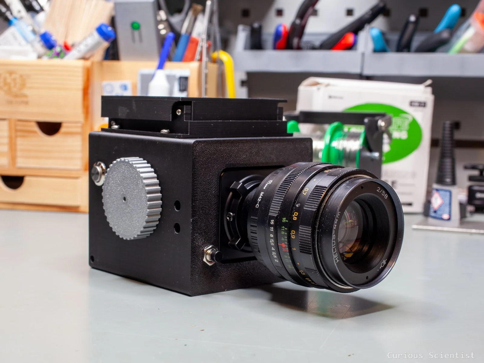
So, I made the camera mimic the look of a Hasselblad camera. Of course, I did not design it to be as nice as the Hasselblad 500C, but there are some tiny similarities like the shutter button, the dial on the right side and the viewfinder on the top side.

The Hawkselblad camera
Mechanical design
The camera has a cubic body that contains everything. It is about 89 mm wide, 82 mm tall and 98 mm long. I tried to design it so it is relatively easy to print. It took 3,5 hours and 108 g PLA filament with my Bambulab X1C printer and I used some tree supports to avoid sagging features.
The front side accommodates the C-mount flange I upcycled from a CCTV camera shell. I used the same C-mount flange for my “cinematic camera” shell, so I kept the idea because it worked just fine. The C-mount flange is attached to the camera via those four ears. Furthermore, there is a small push button on the front which is used as the exposure button.
The right side of the shell has a recessed part that holds my 5-way joytick PCB I designed specifically for the Hawkeye camera module earlier to replace its original, button-based remote. Plus, it also has a hole for the main switch that connects/disconnects the battery from the rest of the circuit.
The left side also has a recess with more features. There are two tiny circular pockets on the side. They are made to hold small 3 mm x 1 mm (D x t) magnets. The rectangular hole allows the user to access the USB-C port and the micro SD card slot on the camera’s processor module.
The bottom has 5 holes, out of which 4 are used to hold the processor module in place, and the 5th, which is right in the centre of the bottom plate. is to accommodate a 1/4” threaded insert for tripod mounts.
The top has a large hole to accommodate the flap mechanism for the display. The mechanism is attached to the main body by four screws, which are screwed into the threaded insert nuts I pressed into the four holes on the two sides of the big opening.
Finally, the back side has a “drawbridge-style” door. The door clicks into place by utilising tightly fitting parts, and it rotates by a simple hinge mechanism I made using brass insert nuts and bolts.
The viewfinder and the flap mechanism are made of four 3D-printed parts. The main part is a “skirt” that connects to the top of the camera body and holds together the other three parts. The bottom side of the skirt has a cutout for the display and four screwholes for the support plate of the display and its driver. Two parts are sitting on the top of the skirt, and they are the collapsible viewfinder. They fold into the skirt and the camera body perfectly by utilising a smart mechanism. The front side of the flap is also the cover of the whole viewfinder. When it is folded down to the closed position, it covers the skirt from all sides. The back side folds down in front of the display when the viewfinder is closed.
The mechanism is based on a “hockey stick” shaped groove on the rear flap. The groove is connected to the front side via screws. To stop the nuts from unscrewing themselves, I locked them with a drop of super glue.
The fourth part of the viewfinder is a holder, a support plate for the display and its driving circuit. On one side, it holds the display in place and on the other side, it holds the driving circuit. The plate has guides that help to position the display correctly, and it also has a cutout so the ribbon cable can go through it. The four holes at the corners are aligned with the four holes at the bottom of the skirt.
The display is a 2” LCD with a 4:3 aspect ratio and a 640 x 240 resolution. It is not a high-resolution display, but it is enough for this purpose. The display connects to the camera via a single cable - it receives the video signal as a composite signal (CVBS). The quality is decent enough, and it provides good flexibility when it comes to cabling.
But the main reason I picked this display is its power supply capabilities. The display driver accepts input voltages from 3 V up to 15 V. So, I could directly power it from a lithium battery. This is another step of flexibility I really liked.


The back side of the C-mount flange with the four ears


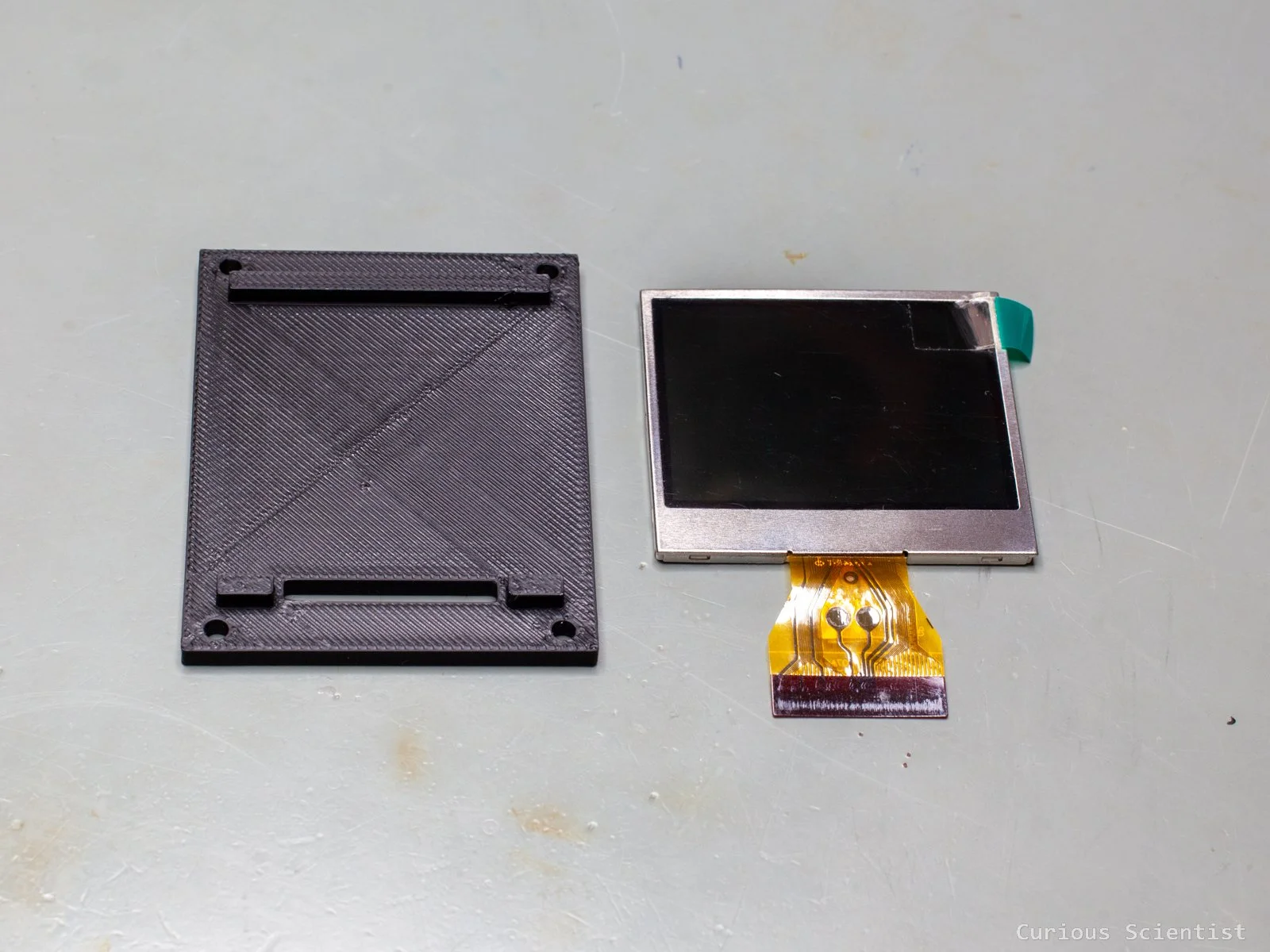
The 3D-printed support plate and the 2” display used in the viewfinder
Before installing the viewfinder, I had to wire everything together. The easiest way to explain it is to start from the battery. The negative pole of the battery was connected to a common node, a 4-slot screw terminal. This node then served as the ground connection for the push button, the camera module and the display. The positive pole first went through the main switch, which is a latching button. Then, the other side of the main switch (the “output”) went into a common node, a 3-slot screw terminal. This then fed the camera module and the display module with 7.4 V. So, when I switch the camera on with the main switch, both the display and the camera module get powered.
Here I want to mention that during the assembly, I used a green colored push button as the shutter button. Towards the end of the assembly process, when I tested the camera, I noticed a weird behaviour from the camera. It was freezing up, and it was constantly trying to take pictures. I realised that I accidentally used a normally closed type of button, so the shutter was constantly triggered, and this made the camera act weird. Later, I replaced the button with a normally open type, so the shutter is only triggered when the button is pressed. When the button is pressed, the shutter line (green cable from the camera module’s 5-wire connector) is pulled to ground, which then triggers the camera to take a picture.
One might notice that the cables are unnecessarily long. Yes, good observation, but until I was sure that everything worked as it should, I wanted to keep the wires as-is, so I do not need to do unnecessary extra work. Plus, in the beginning, I had to route the wires carefully because the viewfinder’s flaps reach deep into the housing when it is closed. The finalised design has much more neat cable management.
Another thing that a careful reader might point out is the screw terminals. If you read the article, but haven’t watched the video, you might think that I left it with exposed pins. I actually covered the metal parts with a Kapton tape to avoid shorting the battery to anything else inside the enclosure. If it were a “final build”, I would have gone with a large heat-shrink tube and would have put the whole thing in it, just to be on the safe side.
The camera processor is mounted inside the housing in a way that its USB-C port and micro SD card slot can be accessed. I did not want to expose these ports directly, so I made a recess that has a magnetic mount for a small door that covers the above-mentioned ports.
The joystick received a serrated wheel. The wheel not only provides an aesthetic feature by covering the otherwise exposed PCB, but it also makes it easier to bump the joystick. Honestly, it is a bit confusing in the beginning to try not to rotate but push the wheel, but after a few minutes, it becomes more comfortable to use it.
The final build received a battery as well. The battery is a 7.4 V, 3000 mAh module, basically two 18650 batteries in series, packed in the typical blue heat shrink foil. The battery pack is attached to the inner side wall via an adhesive velcro tape.
The insides look a bit crowded, but the viewfinder opens and closes normally, and as I mentioned earlier, the final build will get better cable management with proper length.
Get the relevant parts using my affiliate links:
Hawkeye Firefly Split V6 Pro camera
CCTV housing with C-mount flange


The processor module with custom heat sinks and the camera module, both installed in the housing


Hawkselblad with closed viewfinder