ESP32-S3 multiple SPI buses - SPI, VSPI, HSPI, FSPI, WTF…!?
In this article, I will clarify the differences between the different SPI buses on an ESP32-S3 microcontroller, and will show some examples using an ADS1256 24-bit AD converter with my ADS1256 library and an ILI9341 SPI display with Adafruit’s library. The reason why I wrote this article is that I recently had an assignment on this topic, and it was very difficult to find a proper description on the internet. All the typical “go-to websites” have the information wrong. So, the purpose of this article is to become a good help provider on this topic and demystify the use of different SPI buses. Maybe this article can become the “go-to resource” for SPI on ESP32-S3 modules.
ESP32-S3 hardware
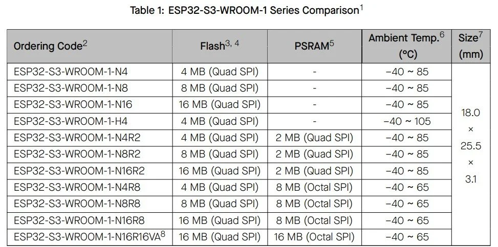
In this demonstration, I am using the ESP32-S3 DevKitC-1 module with an “N8R8” chip on it. The N8R8 means that it has 8 Mb flash (quad SPI) memory (Nx) and 8 Mb PSRAM (Octal SPI) (Rx). There are numerous models in the ESP32-S3-WROOM-1 series, so one must be aware of the naming.
When it comes to SPI, it is very important to know whether the chip has an octal SPI PSRAM or not. According to Espressif System’s documentation, modules with octal SPI PSRAM cannot use GPIO 35, GPIO 36 and GPIO 37 pins because they are used for internal communication between the ESP32-S3 chip and the PSRAM. This is particularly important because the pins are physically available on the board, but if you use them, you will most probably encounter “Guru meditation error” when the module tries to boot (been there, done that).
Before going deeper into the details, let me reiterate the ESP32-S3 Series Datasheet V2.0 regarding the four different types of SPI buses available on the board, and their most relevant properties.
SPI0: It is used by the chip’s GDMA controller and cache to access flash/PSRAM
SPI1: It is used by the CPU to access flash/PSRAM
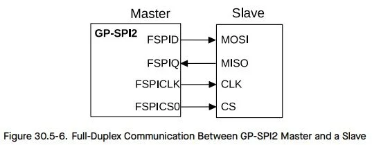
SPI2: general-purpose SPI, also known as Fast SPI, FSPI or GP-SPI2
SPI3: general-purpose SPI, also known as SPI3, GP-SPI3 or HSPI
This means that SPI0 and SPI1 are internally occupied with these specific modules (N8R8!), so we can only use SPI2 and SPI3. But, it is important to note that the alternative SPI pins on GPIO 35 - GPIO 37 won’t work. Other popular websites discussing this microcontroller often (always) wrongly state the pins and their function, so be extra careful where you get your information. For example, they often refer to VSPI, but the S3-series does not have such a thing.
If you dig deeper into the Arduino files and open the esp32-hal-spi.h file, you will see that if you happen to use an S3-series microcontroller, the library will use either FSPI or HSPI:
#if CONFIG_IDF_TARGET_ESP32C2 || CONFIG_IDF_TARGET_ESP32C3 || CONFIG_IDF_TARGET_ESP32C6 || CONFIG_IDF_TARGET_ESP32H2 || CONFIG_IDF_TARGET_ESP32S3
#define FSPI 0
#define HSPI 1
So, logically, SPI2 is FSPI, and SPI3 is HSPI. As you can see, there is no such thing as VSPI for an ESP32-S3 microcontroller!
FSPI can use the default pins of the ESP32-S3, and they are distributed between GPIO 9 and GPIO 14. More precisely, we need GPIO 11 (FSPID), GPIO 12 (FSPICLK) and GPIO 13 (FSPIQ). To decipher the cryptic naming, especially FSPID and FSPIQ (FSPICLK at least makes sense), we can again refer to the datasheet and discover that FSPID is the data in pin, which is the MOSI pin. And FSPIQ is the data out pin, which is the MISO pin. Interestingly, they named the pins from the slave’s perspective: so when they say data in pin, it is the data in pin on the slave device! But, this will actually make some sense when I show the demonstration code because one of the devices I use has DIN and DOUT pins as SPI pins.
In my demonstration, one SPI device -the display- will use the FSPI with the default pins, and another device -the ADS1256 module- will use the HSPI with totally arbitrary pin assignments, but will avoid the GPIO 35 - GPIO 37 pins. So, the first device will be a good demonstration to show how the default SPI (FSPI/SPI2) works, and the second device will be a good demonstration to present the flexibility of the GPIO Matrix feature of the chip, which allows arbitrary pin assignments for HSPI/SPI3. The two devices will work simultaneously, but on different SPI buses, to further demonstrate how everything works.
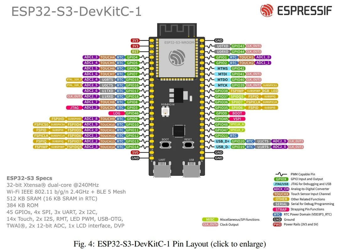
Pinout diagram. Source: Datasheet (click on the picture)
Test setup
To demonstrate the FSPI and HSPI, I used the above-mentioned ESP32-S3 DevKitC-1 module with an ILI9341 LCD and ADS1256 module. The display uses the default FSPI pins, and the ADS1256 uses the HSPI bus with custom pin assignments. The display uses the Adafruit_ILI9341 and the Adafruit_GFX libraries.
If we dig deeper into the Adafruit_ILI9341.h and .cpp files, we will find this block of code that states that if only the “non-SPI” pins are defined in the constructor, then the library will use the default SPI. In this case, this is FSPI, since it is the first general-purpose SPI.
/**************************************************************************/
/*!
    @brief  Instantiate Adafruit ILI9341 driver with hardware SPI using the
            default SPI peripheral.
    @param  cs   Chip select pin # (OK to pass -1 if CS tied to GND).
    @param  dc   Data/Command pin # (required).
    @param  rst  Reset pin # (optional, pass -1 if unused).
*/
/**************************************************************************/
Adafruit_ILI9341::Adafruit_ILI9341(int8_t cs, int8_t dc, int8_t rst)
    : Adafruit_SPITFT(ILI9341_TFTWIDTH, ILI9341_TFTHEIGHT, cs, dc, rst) {}
The ADS1256 module uses my own ADS1256 Arduino library. The library allows custom SPI pins; we just have to tell which SPI bus we use, and then we have to pass the SPI pins to this custom SPI and initialise it. So, I assigned the HSPI bus with custom pins.
SPIClass spiADS(HSPI);
ADS1256 A(ADC_DRDY, ADS1256::PIN_UNUSED, ADC_SYNC, ADC_CS, 2.500, &spiADS);

void setup()
{
    spiADS.begin(ADC_SCK, ADC_MISO, ADC_MOSI, ADC_CS);
}

Photo of the actual setup
Coding and demonstration
To make it into a spectacular demonstration, I connected a 100-gram load cell to the A0-A1 differential input of the ADS1256 module. The ILI9341 display will draw a continuous rolling chart of the output voltage of the load cell. I did not calibrate the load cell; therefore, I just plotted the output voltage. It does not matter for this demonstration whether the display shows ADC code, voltage or grams…etc. In addition to the graph itself, I also print the actual value of the most recent reading on the display, plus I send the data to the serial port so I can confirm the readings.
This is a good demonstration to show that both devices can work on separate SPI buses, plus it can also show that the display can operate at a high refresh rate without any lagging or glitches. With software SPI, the display would have a hard time keeping up with the roughly 60 FPS frame rate.
Regarding the ADS1256 code, there is really nothing to explain, because I simply recycled the example code from my library, and I added an extra case to the switch-case block that starts an acquisition and plots the sampled values on the display. The only difference is that I cleaned up the example file, and I just kept the project-specific lines. That is actually what the previous section shows. Those three lines are the lines that were changed slightly.
Therefore, I will pay more attention to the display part. I basically embedded the display-related code into my ADS1256 example code, so it is more interesting to talk about the display-related lines.
The core code I want to discuss here is the one that adds the samples to the “oscilloscope” I made for the display. It is not really an oscilloscope; it is rather a rolling chart.
This function is called in each loop() iteration in the main code, and it receives a conversion result from the ADS1256 as a floating-point number. The number is simply the measured voltage on the A0-A1 differential input, generated by the load cell connected to it.
The code works along the following principles:
The function stores the new sample in a ring buffer called scopeValues[]. The scopehead keeps track of the sample’s position, and when its value reaches the size of the display area, it wraps to 0 and starts to fill up the array again.
The code checks the number of valid samples. Simply because we need at least 2 points to draw a line. So, if we have just one point, we jump out of the function and carry on.
The code searches for the minimum and maximum Y values on the visible chart area for dynamic autoscaling. Both vMax and vMin start from the same value, and as the code walks through the samples, it checks the items in the scopeValues[] array and checks if the actual value could be smaller than vMin or larger than vMax. Later, these values are used when the actual values are mapped into pixel values along the Y-axis.
The framebuffer is cleared by replacing every pixel with the background colour. It is just a nested loop formalism that goes through all items of a matrix (scopeBuffer[][]) and replaces each item with the background colour (black).
The horizontal lines are redrawn. These are just some equally placed lines to help guide the eyes of the user.
The actual trace is put into the framebuffer. The actual pixels cannot have fractional values; they can only be integers, so the Bresenham’s algorithm is used to draw straight line sections between adjacent points.
Finally, the framebuffer is sent to the display.
Another interesting function can be the mapToY() function. This function converts the readings into pixel values on the display.
First, to make sure that the code does not have to perform a division by zero, we “nudge” the vMin if it is the same value as vMax. The necessity of this code block will make more sense when we look at how n is calculated. The denominator has (vMax - vMin), and if they are equal, the term would become zero. So, this is why we need the “nudging”.
Then, another check is done in order to clamp the out-of-range values. Negative values are clamped to 0 because the smallest pixel value will be zero. And, the largest values will be one.
Still, the n is just a number between 0 and 1. It is a normalised value that we are going to use as a multiplier.
In the last line, this is what we see. The (1-n) is just because of how we measure the display coordinates. Then the result of this is multiplied by the number of vertical pixels - 1. The result is cast into an integer because the pixels cannot be fractional values.
static int mapToY(float v, float vMin, float vMax)
{
  if (vMax == vMin)
  {
    vMax = vMin + 1.0f;
  }

  float n = (v - vMin) / (vMax - vMin);

  if (n < 0)
  {
    n = 0;
  }

  if (n > 1)
  {
    n = 1;
  }

  return (int)((1.0f - n) * (SCOPE_HEIGHT - 1));
}
Finally, the pin layout is also useful information. Instead of spending a lot of time on drawing the circuit diagram, I simply list the pins. You just need to be able to read to understand which GPIO pin on the ESP32 is connected to which pin on the ADS1256 and the display.
I named the variables with self-explanatory names. Their name is the pin on the given module and the numbers are the GPIO pin numbers on the ESP32. You can see that the ADC avoids the GPIO 35 - GPIO 37 pins and that the LCD uses the default pins of the FSPI bus.
constexpr int ADC_DRDY = 4;
constexpr int ADC_CS = 2;
constexpr int ADC_RST = 16;
constexpr int ADC_SYNC = 18;
constexpr int ADC_SCK = 38;
constexpr int ADC_MOSI = 1;
constexpr int ADC_MISO = 41;

constexpr int LCD_CS = 21;
constexpr int LCD_RST = 17;
constexpr int LCD_DC = 10;
constexpr int LCD_LED = 42;
constexpr int LCD_MOSI = 11;
constexpr int LCD_SCK = 12;
constexpr int LCD_MISO = 13;
Get the relevant parts using my affiliate links
ESP32-S3 DevKitC-1 compatible board
If you found this content useful, please consider joining my YouTube channel’s membership or leaving a donation.
Also, please consider using my affiliate links when buying relevant gadgets.
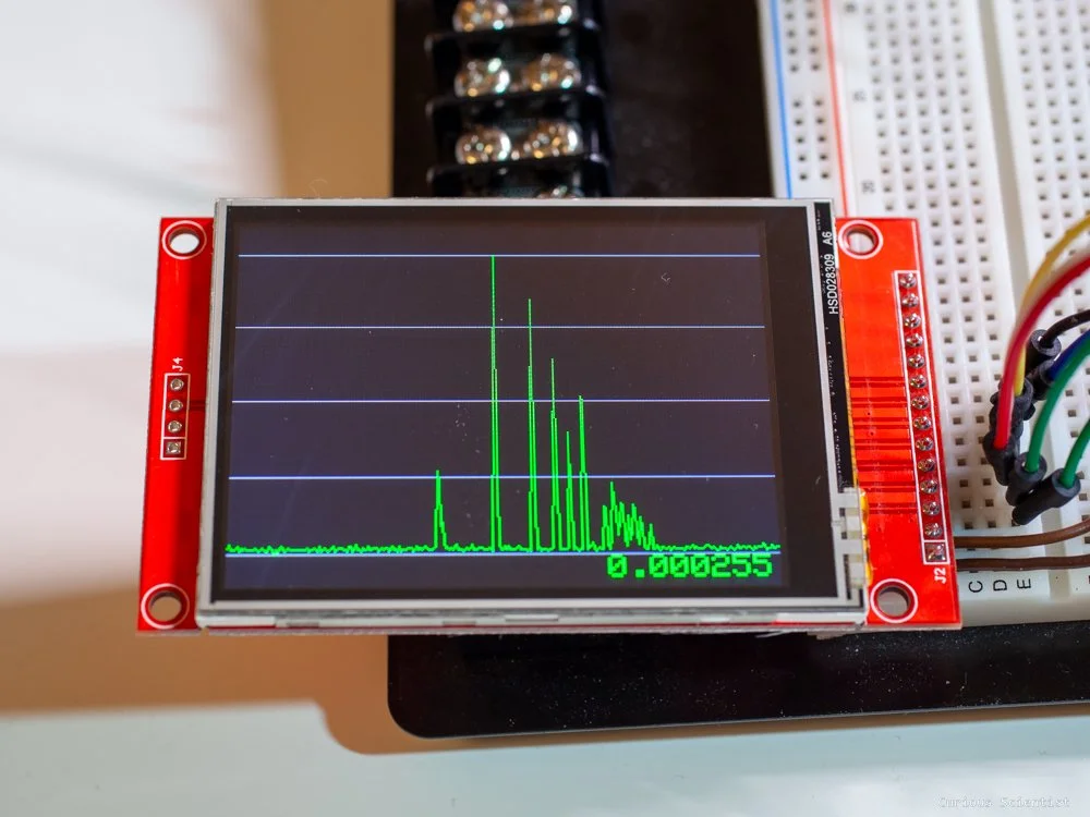
Photo of an actual real-time graph. I bumped the load cell a few times.
void scopeAddSample(float sample)
{
  scopeValues[scopeHead] = sample;
  scopeHead++;

  if (scopeHead >= SCOPE_WIDTH)
  {
    scopeHead = 0;
    scopeFilled = true;
  }

  int count = scopeFilled ? SCOPE_WIDTH : scopeHead;

  if (count < 2) return;

  float vMin, vMax;
  {
    int start = scopeFilled ? scopeHead : 0;
    int index = start;
    vMin = vMax = scopeValues[index];

    for (int i = 1; i < count; i++)
    {
      index = (start + i) % SCOPE_WIDTH;
      float v = scopeValues[index];
      if (v < vMin)
      {
        vMin = v;
      }
      if (v > vMax)
      {
         vMax = v;
      }
    }
  }

  for (int y = 0; y < SCOPE_HEIGHT; y++)
  {
    for (int x = 0; x < SCOPE_WIDTH; x++)
    {
      scopeBuffer[y][x] = SCOPE_BG;
    }
  }

  for (int i = 0; i <= 4; i++)
  {
    int gridY = (SCOPE_HEIGHT * i) / 4;

    if(gridY < 0)
    {
      gridY = 0;
    }
    if(gridY >= SCOPE_HEIGHT)
    {
      gridY = SCOPE_HEIGHT - 1;
    }

    for (int x = 0; x < SCOPE_WIDTH; x++)
    {
      scopeBuffer[gridY][x] = SCOPE_GRID;
    }
  }

  int start = scopeFilled ? scopeHead : 0;
  int index0 = start;
  int y0 = mapToY(scopeValues[index0], vMin, vMax);

  for (int i = 1; i < count; i++)
  {
    int index1 = (start + i) % SCOPE_WIDTH;
    int y1 = mapToY(scopeValues[index1], vMin, vMax);
    int x0 = i - 1;
    int x1 = i;
    int dx = abs(x1 - x0);
    int sx = x0 < x1 ? 1 : -1;
    int dy = -abs(y1 - y0);
    int sy = y0 < y1 ? 1 : -1;
    int err = dx + dy;
    int e2;
    int xx = x0;
    int yy = y0;

    for (;;)
    {
      if (xx >= 0 && xx < SCOPE_WIDTH && yy >= 0 && yy < SCOPE_HEIGHT)
      {
        scopeBuffer[yy][xx] = SCOPE_TRACE;
      }

      if (xx == x1 && yy == y1) break;

      e2 = 2 * err;

      if (e2 >= dy)
      {
        err += dy;
        xx += sx;
      }

      if (e2 <= dx)
      {
        err += dx;
        yy += sy;
      }
    }
    y0 = y1;
  }

  tft.drawRGBBitmap(SCOPE_X, SCOPE_Y, (uint16_t*)scopeBuffer, SCOPE_WIDTH, SCOPE_HEIGHT);
}