A genius way of handling multiple buttons
In this article, I show you a genius way of handling multiple buttons with a microcontroller. I “discovered” this method when I got my Hawkeye Firefly Split V6 PRO camera and used its remote controller. The remote controller has 5 buttons, but there are only two cables coming from it. This made me curious; therefore, I reverse-engineered the circuit and studied its working principles. Below, I will show you everything about the circuit, and I will explain how you can make your own circuit based on the principles I present.
Introduction
As I mentioned earlier, I was initially puzzled by this remote: it has only two wires despite featuring five buttons. In a typical implementation, each button would be assigned to its own GPIO pin, with the internal pull-up resistor enabled for each input. By that logic, the module should require six wires (five signals plus ground), not two.
So, what’s going on here?
The designer used a clever approach.
In this remote, all buttons share a common ground return. One button - the DOWN button - connects the signal line directly to ground, bypassing all onboard resistors. The remaining four buttons each connect a dedicated resistor to ground when pressed:
UP → 15 kΩ
LEFT → 27 kΩ
ENTER → 45.3 kΩ
RIGHT → 6.8 kΩ
On the main board, the other wire from the remote connects to an ADC input via a pull-up resistor (presumably around 10 kΩ) tied to the supply rail (assume 5 V for this example). The second wire from the remote is tied to system ground.
When no button is pressed, the ADC pin is pulled high to VCC through the pull-up, with the remote’s resistors effectively floating. Pressing one of the four resistor-equipped buttons completes a voltage divider between the pull-up resistor on the main board and the corresponding resistor in the remote, producing a distinct voltage at the ADC input. By reading this voltage, the firmware can determine which button was pressed.
The DOWN button is the exception: when pressed, it shorts the ADC pin directly to ground through zero ohms, producing a reading of (ideally) 0 V.
In summary, this design uses a resistor ladder to multiplex multiple button inputs into a single ADC channel, reducing the wiring requirement from six conductors to just two.
I summarised the necessary details for each button press in the table below.
| Function | Resistor to GND | Divider Formula (Vnode) | Expected Vnode (V) | Expected ADC (10-bit) |
|---|---|---|---|---|
| NONE | Open | 5·open | 5.000 | 1023 |
| DOWN (C) | 0 Ω (direct) | 5·0/(10k+0) | 0.000 | 0 |
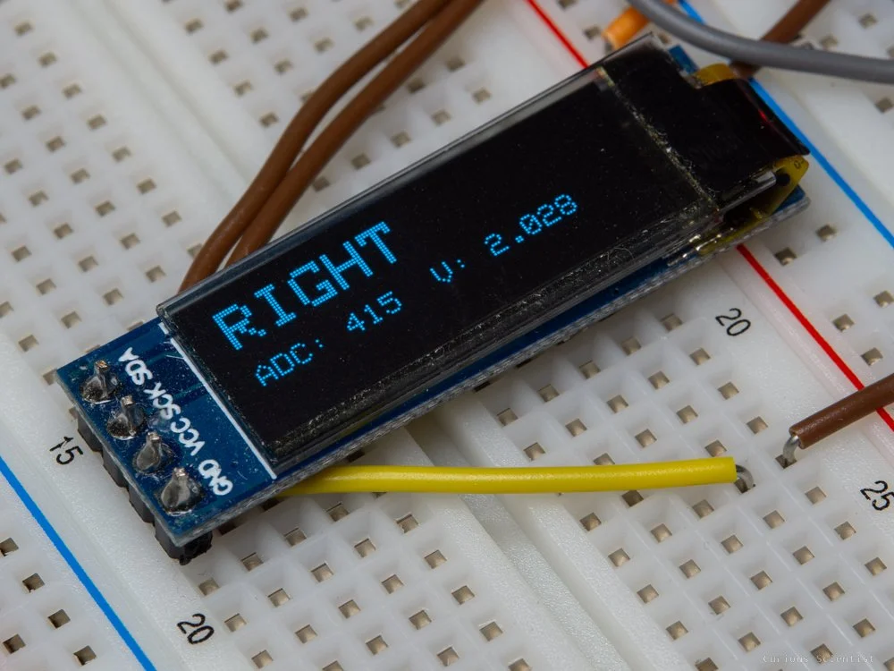
| RIGHT (E) | 6.8 kΩ | 5·(6.8k)/(10k+6.8k) | 2.024 | 414 |
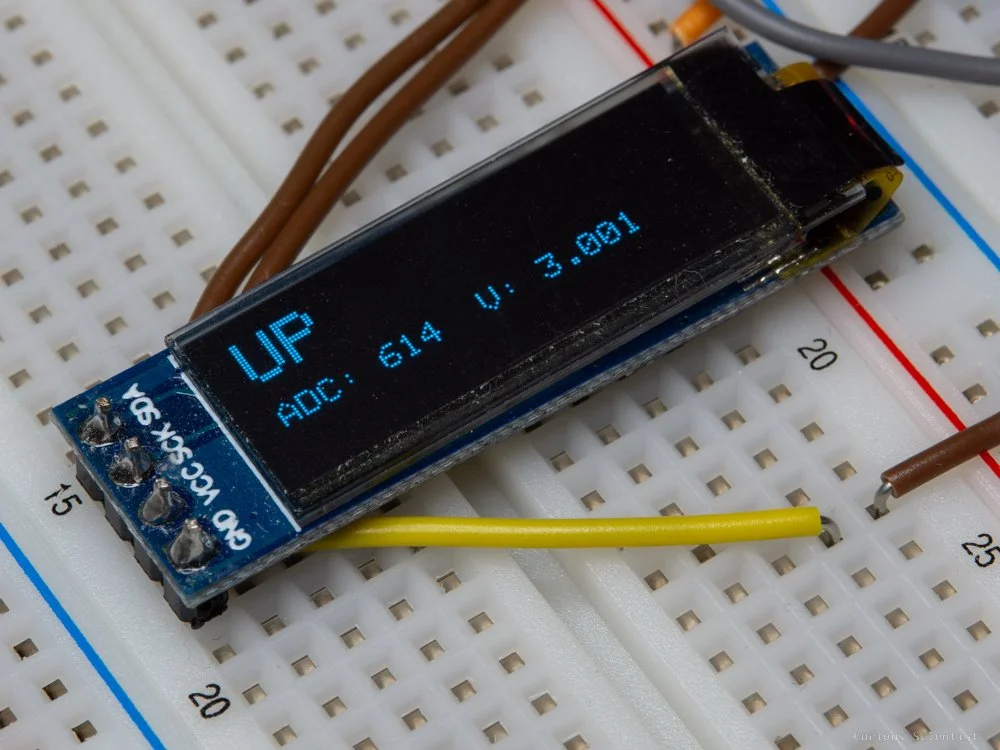
| UP (A) | 15 kΩ | 5·(15k)/(10k+15k) | 3.000 | 614 |
| LEFT (B) | 27 kΩ | 5·(27k)/(10k+27k) | 3.649 | 747 |
| OK (F) | 45.3 kΩ | 5·(45.3k)/(10k+45.3k) | 4.096 | 838 |
My Hawkeye camera’s 2-wire remote controller.

Reverse-engineered circuit of the remote controller.
Of course, no circuit is without its limitations.
From the table above, it’s clear that the intended detection method is to identify a specific button press by measuring the corresponding voltage at the ADC input. For instance, if the ADC returns a code of approximately 414 (≈ 2.024 V), the firmware can infer that the RIGHT button is pressed.
However, this only holds true if the supply voltage is close to 5 V and the resistor values match their nominal specifications. The resistor tolerances can be addressed by using precision components -1 % or better. Supply voltage is less controllable, but with a quality USB power source, it will usually be close enough to 5 V. In addition, the firmware can implement an initial calibration routine to determine the actual ADC codes for each button at runtime, further compensating for component and supply variations.
Another potential complication arises if two buttons are pressed simultaneously - for example, moving the switch diagonally so that two resistors are connected to ground in parallel. This would produce an “invalid” ADC code that does not correspond to any single button, making identification ambiguous. Fortunately, in this particular design, the physical construction of the 5-way switch prevents true simultaneous actuation of two directional buttons. Even if it were possible, the application (navigating a camera menu) provides no meaningful scenario for pressing two buttons at once - pressing UP and LEFT simultaneously, or ENTER together with any other key, has no functional value. From both a mechanical and logical standpoint, it’s safe to assume that only one button will be pressed at a time.
Because high-precision resistors yield stable, repeatable voltage levels, the same method can be extended to support a greater number of inputs on a single ADC pin. By carefully selecting resistor values, multiple distinct voltage levels can be created, allowing many more buttons to be multiplexed onto one analogue input -provided the one-button-at-a-time assumption still holds.
struct Button
{
  const char* name;
  int expected;
};

Button buttons[] =
{
  {"DOWN",   0},
  {"RIGHT",  414},
  {"UP",     614},
  {"LEFT",   747},
  {"OK",     838},
  {"NONE",   1023}
};

const char* selectByTolerance(int adc)
{
  for (int i = 0; i < numberOfbuttons; i++)
  {
    if (abs(adc - buttons[i].expected) <= tolerance)
    {
      return buttons[i].name;
    }
  }
}
Core algorithm of the Arduino code that determines which button was pressed
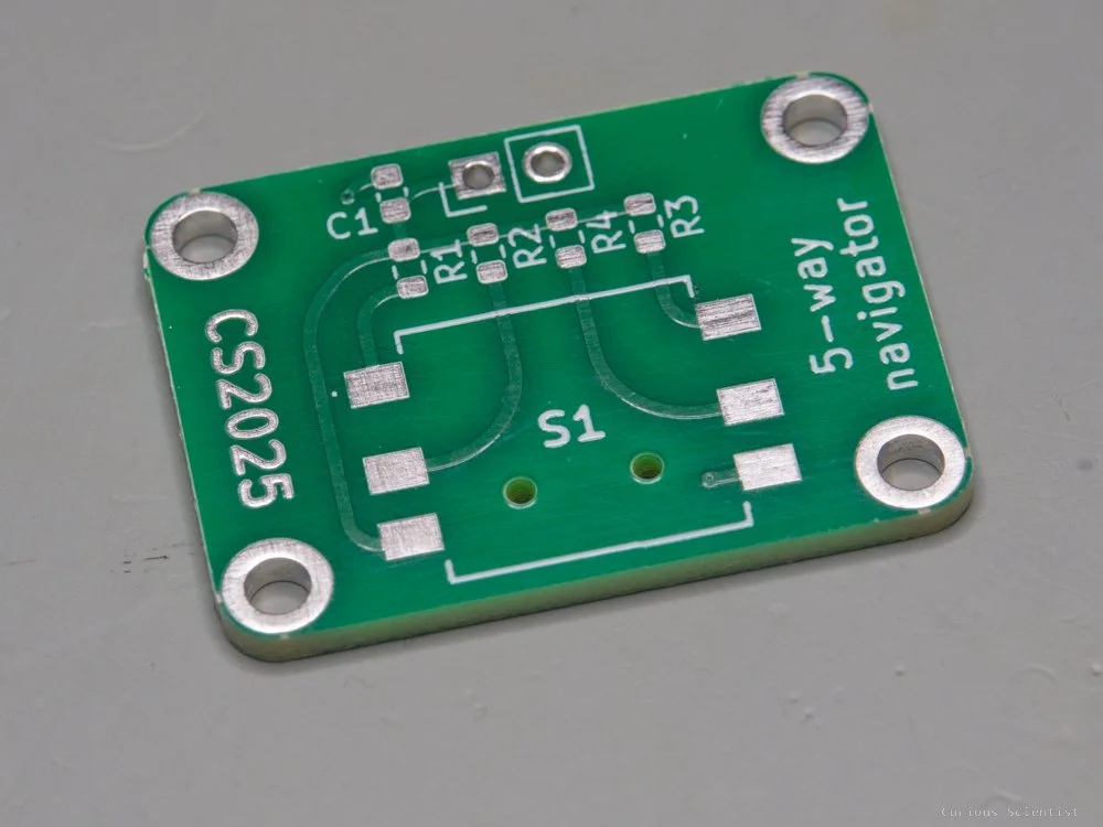
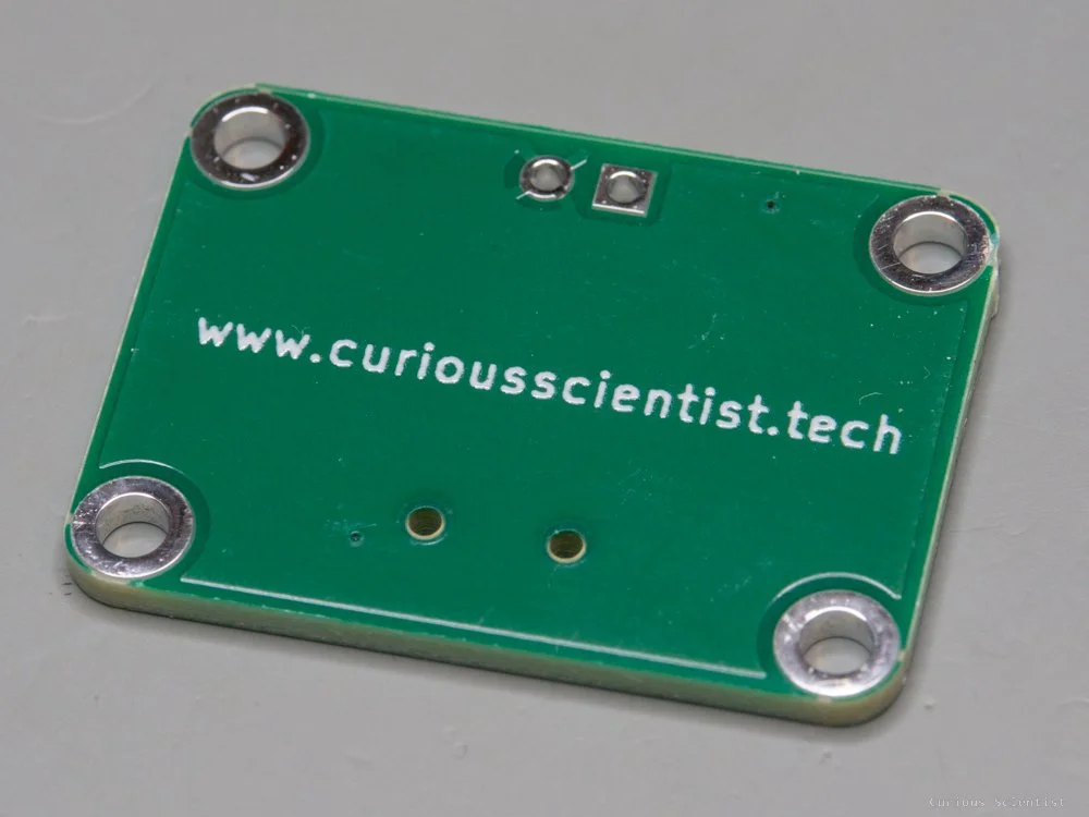
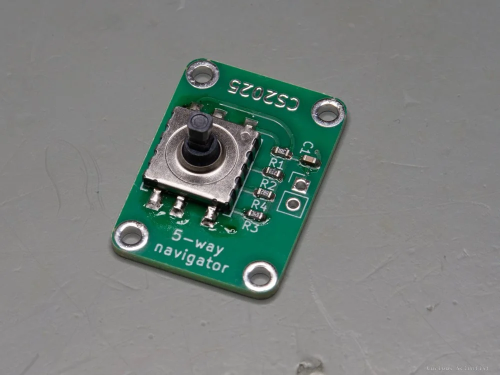
Custom circuit
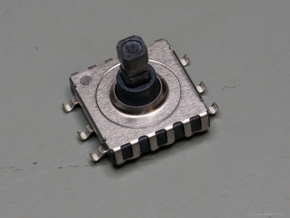
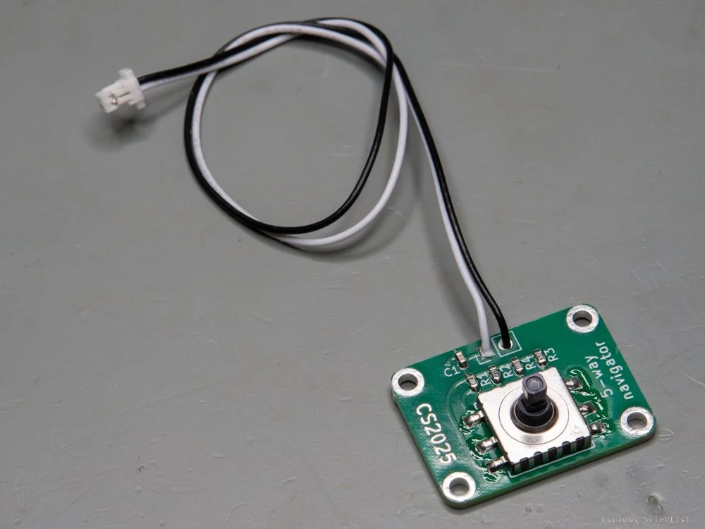
So, of course, I had to add my own twist to this circuit. To continue the elegance of having so few wires, I also reduced the number of components. Instead of five buttons, I used a MU-AS90R multidirectional switch in my circuit. This made it possible to halve the size of the original board while still having four mounting holes on it.
With this improvement, the circuit becomes easier to assemble and easier to use as well. The switch basically acts as a joystick; however, it does not have tilt angle-dependent values. It is just ON/OFF in a certain direction.
I also added mounting holes to the PCB. The camera’s original remote control does not have any mounting points, so it can only be glued to a surface. This makes it cumbersome to use.
The circuit is not only useful for my camera but for any application where you would need a 5-way navigation. For example, if you create something where you need to navigate in a menu, this circuit is perfect. It allows navigation in all directions, plus it has the 5th option, which could be used as an “enter” button.

Additional resources
Get the relevant parts using my affiliate links!
Get the PCB from PCBWay!

Become a channel member!