In my recent project, I made an RGB ring light for my macro camera setup to provide adjustable light for the subjects I record and take pictures of. In the meantime, I kept searching for different LED solutions, and I stumbled upon the SK6812 family. I discovered that they share a lot of common things with the popular WS2812B ‘NeoPixel’ RGB LEDs that I used in the ring light, and they have even more capabilities and versions.
I am introducing two versions in this article. The SK6812 RGB-NW, which is an RGB light source with an additional natural white (NW) LED in the same package as the three individual red, green and blue LEDs. This additional LED produces a much clearer white colour, so the LED can be an even better candidate for macro lights while maintaining the possibility of adding tones by activating the individual red, green and blue LEDs. The SK6812 WWA is a white LED with two different whites and an amber LED. There is a blue-white LED for colder white and a warm-white LED for warmer white colour. The third, amber LED produces a relatively narrow band of yellow (amber) wavelength to provide additional warmth to the light.
Introduction
These LEDs resemble the famous WS2812B “NeoPixel” chips. Same 5050 packaging, same pin arrangement and basically the same control principles. We can use these chips as a drop-in replacement for the WS2812B chips with essentially no effort.
The SK6812 RGB-NW is a bit different from a regular WS2812B chip because it also has a dedicated white (NW - “Natural white”) LED built in. This allows us to produce a much better white light than by simultaneously switching on all three base colours, red, green and blue. Actually, this LED family has BW - blue white, and WS - warm sunlight white LED versions as well. The difference between these three products is the colour temperature of the white LEDs. BW provides a colour temperature around 6000-7000K, NW is around 4000-4500K, and WS is around 2700-3000K. I will only focus on the NW version because I have this type, but the other two LEDs are controlled in the exact same way, so there’s no difference other than the emitted white light’s colour temperature.
The SK6812 WWA differs more. There are no red, green and blue LEDs on this one. Instead, there is a “blue-white”, a “warm-white”, and an amber LED in the package. The white LEDs’ difference can be found in the proportion of the intensities in their blue and yellowish colours. While the “blue-white” (obviously) has a more intense blue contribution, the “warm-white” produces a light that has more pronounced yellow colours. The amber LED is then just an LED with a wavelength between 585-595 nm, according to the datasheet.
Back to the similarities between this chip family and the WS2812B: it is not only the packaging and the pin layout, but the control signal of the LED is also very similar. A small tweak to my already existing SPI driver allowed me to control these LEDs with my CH32 evaluation board. But this is not surprising at all, because the LEDs work using the exact same principles.
There are three types of pulse sequences that control the LED:
Code 0
SK6812 RGB-NW: consists of a 300 ns HIGH pulse and a 900 ns LOW pulse
SK6812 WWA: consists of a 300 ns HIGH pulse and at least an 800 ns LOW pulse
Code 1
SK6812 RGB-NW: consists of a 600 ns HIGH pulse and a 600 ns LOW pulse
SK6812 WWA: consists of a 600 ns HIGH pulse and at least a 200 ns LOW pulse
Reset, which is at least an 80 us long LOW pulse for both chips
So, same, roughly 1.2 us long packages for CODE 0 and 1 and a bit longer reset code. The HIGH pulses are somewhat restricted in a sense that for the WWA LED, they have an explicit upper limit. T0H can’t be longer than 400 ns, and T1H can’t be longer than 1 us. Still, the two types of LEDs can run with the exact same code, with the only difference that the RGB-NW needs a 4th byte to control the white LED. So, the RGB-NW is controlled by 32-bit packages and the WWA is controlled by 24-bit packages.
This also means that the LEDs could be used as a drop-in replacement for the WS2812B LEDs, and only a tiny modification to the code is required.
This tiny modification is due to the slightly different timing and the fact that the additional colour requires an additional 8-bit code. So, instead of 24-bit packages, we need to send out 32-bit packages. Plus, the WS2812B expects the colours in G-R-B order, and here we have R-G-B-W.
Each colour’s brightness level is represented by 8 bits. 0 means that the LED is OFF, and 255 means full brightness. The LEDs consume 8.13 mA (R), 8.20 mA (G), 8.23 mA (B), and 16.56 mA (W), and when all LEDs are ON, the total (measured) consumption becomes 40.4 mA. The total consumption is really close to the sum of the individual consumptions (41.12 mA). Let’s also not forget that these LEDs have an onboard controller chip that is awake even when the individual LEDs are off. Therefore, the chips draw some current even when they are not driving any of the LEDs. This can have an impact on battery-operated projects; therefore, it is good to know the current draw. I measured 256 uA as standby consumption. This could be excessive for certain applications, especially when considering that even high-performance microcontrollers with wireless capabilities can deep-sleep while using sub-ten microamps. But we can always directly switch the supply pin to avoid unnecessary current “leakage”.
Similarly, in the WWA LED, the blue-white LED draws 11.45 mA, the warm-white LED draws 11.27 mA, and the amber LED draws 11.32 mA. So, the individual LEDs’ consumption is basically the same. The measured total consumption is 33.57 mA, which is very close to the sum of the individual consumptions (34.04 mA). Similar to the RGBNW LED, this one also has an onboard controller. It draws 276 uA while the LEDs are off.
SK6812 WWA (in focus) and SK6812 RGBNW (slightly out of focus)
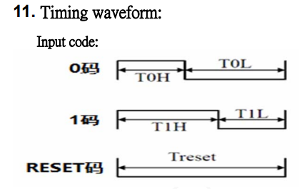
Timing waveforms of both type of chips. Only their pulse lengths differ a bit.
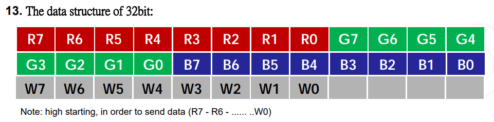
SK6812 RGBNW’s 32-bit data structure
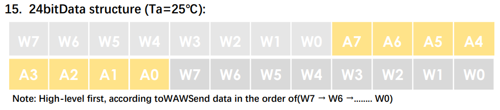
SK6812 WWA’s 24-bit data structure
Colour and brightness
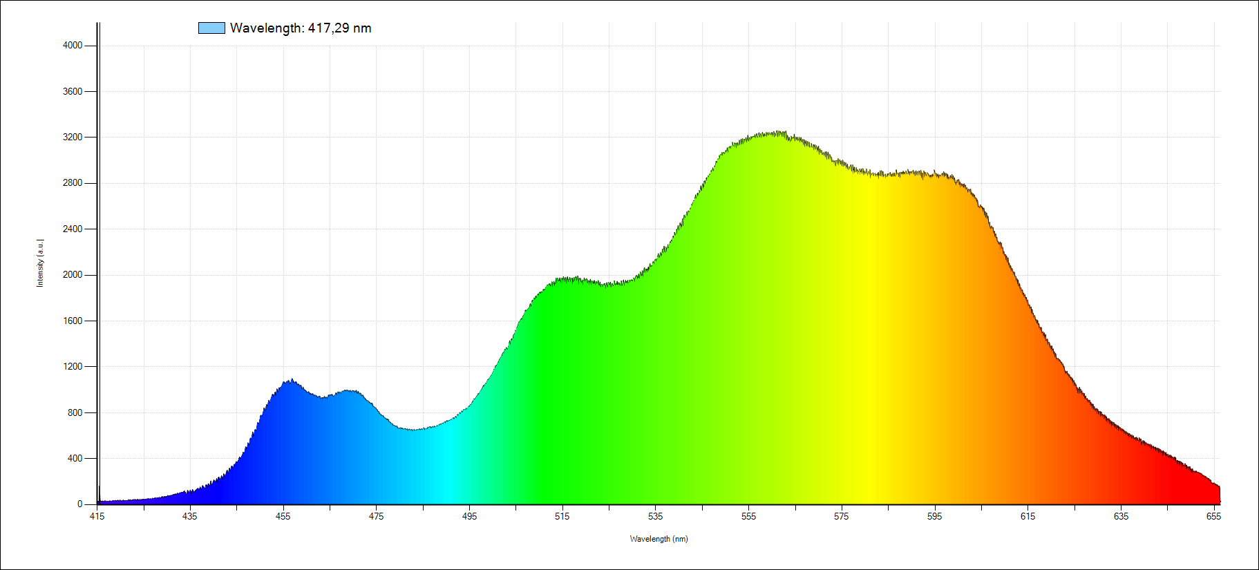
To check the colour and the brightness of the LED, I did some semi-scientific evaluation. I used my spectrometer to determine the spectrum of the individual LEDs. This can help us compare the white colour produced by the white LED and by mixing the three colours together. This is an interesting topic, because if we want to use the LEDs to illuminate subjects that we want to photograph, it is important to render the subject’s colours properly. By rendering, I mean that we are using a light source that reveals the colours of the subject faithfully. As a reference, daylight is considered to be providing CRI = 100, so a perfect score. I don’t have the tools and the knowledge to properly determine the CRI value of these LEDs, so I won't dig deeper, and I will just rely on objective observations.
According to the datasheet, the SK6812 RGB-NW has the following wavelength values for the base colours:
Red: 620-630 nm (628 nm)
Green: 515-525 nm (520 nm)
Blue: 460-470 nm (466 nm)
The measured values are in parentheses. So, it seems that both the datasheet and my calibration are good because my measurements ended up in the middle of the provided ranges. Sure, my curve-fitting technique was very qualitative, but the results were really promising.
Obviously, since the white colour is a mixture (or maybe it is better to say combination) of ALL wavelengths within the visible spectrum, I can only measure its spectrum and qualitatively compare it to the peaks and their spread of the individual LED’s.
When comparing the spectrum of the white LED and the three individual LEDs, we can quickly spot a few obvious differences. The individual LEDs produce three distinct, slightly spread-out peaks around the nominal wavelengths. There is a small gap in the spectrum around 495 nm (cyan) and a wider one between 555 nm and 600 nm (yellow). The white LED produces a more continuous spectrum, but it has its unique features, too. The blue light is split into two peaks, and the previously mentioned lack of intensity around 495 nm can be noticed on this spectrum as well. Then, there’s a relatively nicely distributed spectrum up to about 630 nm and then “deeper” reds are absent.
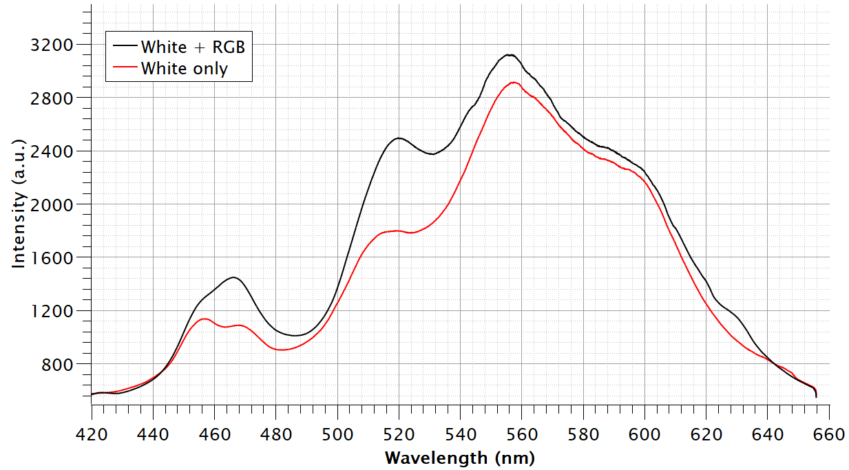
Having the RGB LEDs beside a “native white” LED mainly allows us to adjust the strength of red and blue tones. These individual LEDs have a stronger intensity than that of the white LED’s blue and red components. In fact, even the green shoulder around 520 nm can be pushed up a bit by turning on the individual green LED.
So, with this, it seems to be possible to have a more or less proper white spectrum using the native white LED, and then we can adjust its tone by enabling the individual red, green and blue LEDs. The most noticeable effect can be produced by the blue LED, but the green LED also shifts the intensity around 520 nm quite noticeably. The red LED, however, has only a mild effect.
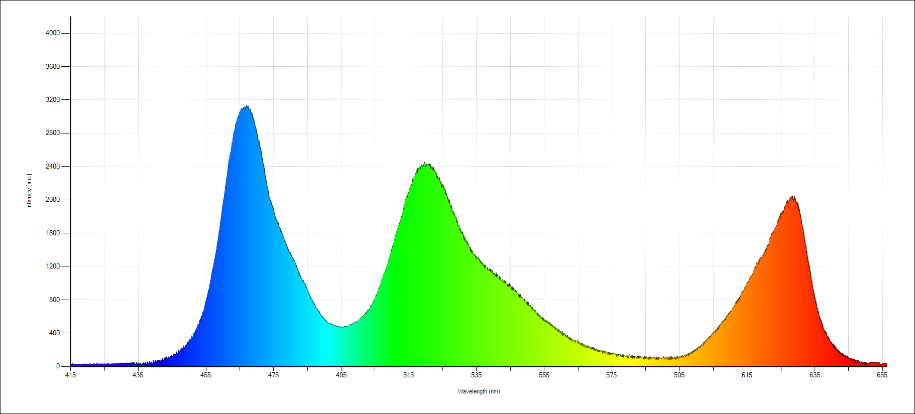
Red, green and blue LEDs individually shining at the spectrometer
White LED shining at the spectrometer
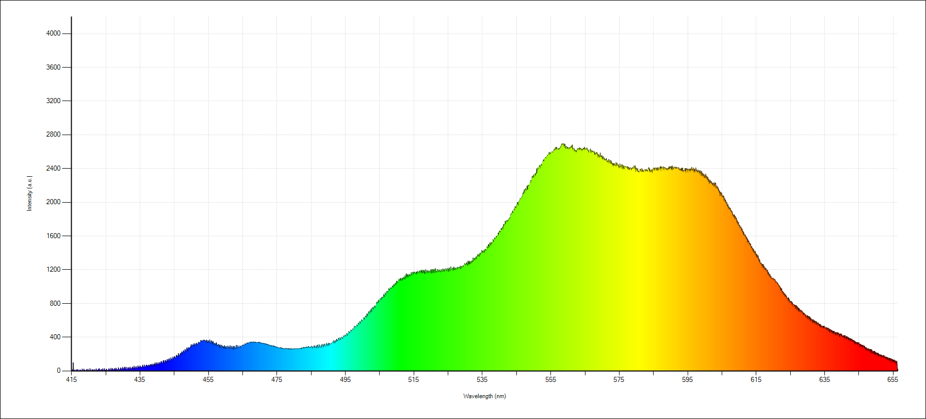
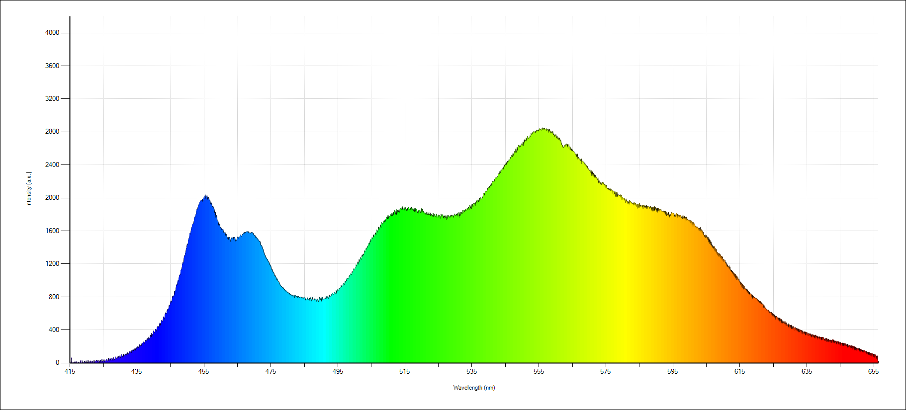
The colour distribution is rather similar when looking at the spectra of the WWA LED. As mentioned earlier, we have two native white LEDs, one colder and one warmer and a standalone amber LED inside the 5050 package.
The difference between the warm white and blue white spectra is the amount of blue light in the spectrum. As one would expect, the blue-white LED emits more blue. Furthermore, it has a more pronounced green peak around 515 nm.
Then finally, the amber LED is just a relatively narrow peak at roughly 590 nm. This LED adds warmth. Also, it is worth noticing that this LED has about 4-6x less brightness than the other two, so it does not contribute to the overall spectrum too much.
When it comes to driving the LED, I think it is enough to talk about it very briefly. The code is almost exactly the same for the WWA LED as for the WS2812B LED. The differences are just in the naming conventions. Plus, I published the code on my GitHub, so you can download it and experiment with it as you wish.
The principles are the same: CODE 0 and CODE 1 are built up by pulsing the MOSI pin. When a carefully selected SPI prescaler is chosen (16), the period of a pulse (48 MHz / 16 = 3 MHz → 333.3 ns) can be used to build CODE 0 and CODE 1. CODE 0 is 1000, and CODE 1 is 1100, which means that CODE 0 is high for 333.3 ns and low for 1 us, and CODE 1 is high for 666.6 ns and low for the same amount of time.
Then, the WWA LED is super simple: there are 3 colours; each colour needs 8 bits, where each bit is represented by CODE 0 or CODE 1. So, each bit is 4 SPI bits. Therefore, one colour is 8×4 = 32 SPI bit; hence, the total required bit per LED is 96 (or 12 bytes). The rules are exactly the same for the RGB-NW LED, but since we have an additional colour, the final sum is 128 SPI bits per LED. Knowing these values allows us to estimate the number of LEDs we can control via SPI. Depending on which type of LED we use, my CH32V006K8U6 could drive 300-400 LEDs simultaneously. The results might differ with other MCUs that have less or more RAM.
For us, humans, it is easier to tell the program that we want a certain LED at a certain brightness. For example, red at 128, green at 55, blue at 207 and white at 255. A simple code translates these brightness values into “SPI bytes” by checking each colour’s (human-readable) value. The code works through the bits of the 8-bit binary value that represents a colour, and for each bit, it creates a 4-bit SPI nibble. The final values are packed into a buffer.
Then, we just need to assign a colour to the LED and pass it to the LED by sending out pulses from the MOSI pin of the microcontroller.
Affiliate links for relevant products:
If you found this content useful, please consider joining my YouTube channel’s membership or leaving a donation.
Also, please consider using my affiliate links when buying relevant gadgets.
Warm white
Blue white
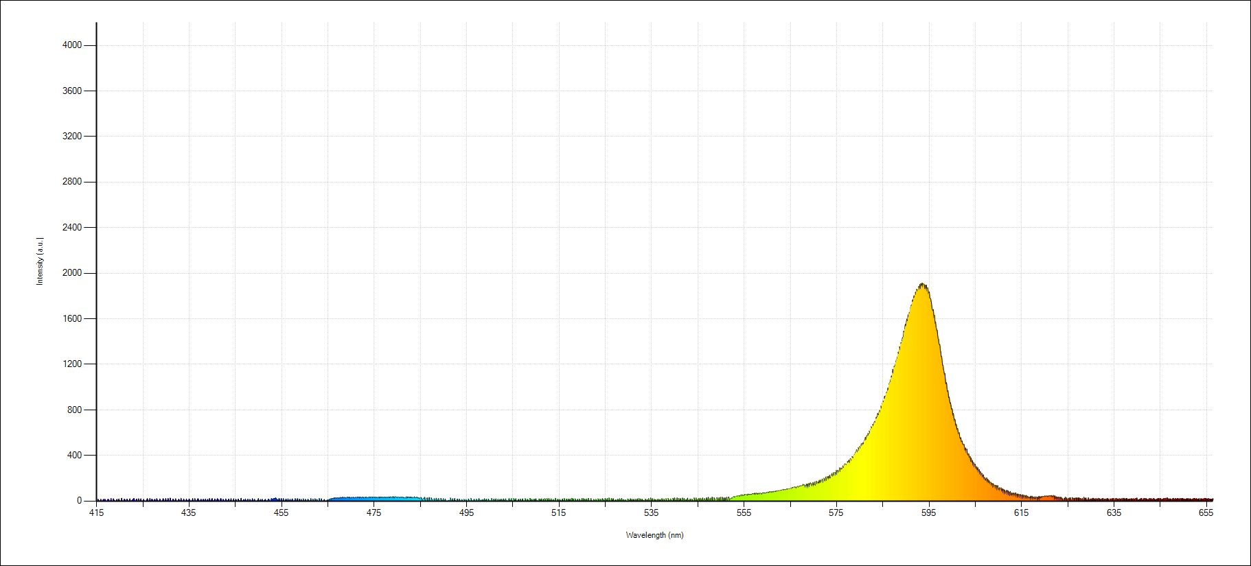
Amber