CH32V006K8U6 development board under $5
In this video, I show you how I built my own development board based on the cheap but powerful CH32V006K8U6 microcontroller. I’ve been using the ‘V003-series chips for a while but sometimes, especially when using it with an SD card reader, I felt that the memory was too low. This microcontroller solves the issue since it packs 62k flash memory and 8k RAM. Since it is so cheap, I decided to make my own development board based on this chip so I could add more exciting content to my CH32 tutorial series.
Introduction
So, I have been working with the CH32 microcontrollers and chips for a while, and I even designed some simple circuits with them, such as my miniature breadboard voltmeter, or my USB PD breadboard power supply. This time, I picked a little more advanced microcontroller and designed a development board around it. I think it is particularly useful because, apart from the manufacturer’s development board, there are no easy-to-buy designs available according to my research. The “problem” with the manufacturer’s evaluation board is that it is way too large, and it is impossible to plug it into a breadboard. Therefore, it is very cumbersome to build test circuits around it. My circuit aims to resolve this issue through its streamlined design.
Capabilities
I won’t go through all the specifications here, but still, I would like to highlight some if the interesting features of this chip. I took the Arduino Nano’s microcontroller, the ATmega 328, as a reference because both boards (the full PCB) cost roughly the same. Sure, the two chips are nearly 20 years apart, so there is a large technological gap between them, but to understand the key differences, it is still fair to compare them, perhaps.
Their CPU frequency differs a lot. The CH32 has a 3x higher CPU frequency at 48 MHz. The memory, both flash and RAM, is better for the CH32. The flash is 32k vs. 62k, and the RAM is 2k vs 8k. The CH32 is obviously stronger here.
When it comes to the GPIO pins, they are almost the same if we look at the boards and not the chips. My board does not utilize all the 31 GPIO pins of the CH32V006K8U6 chip. I reserved 2 pins for the onboard USART-to-USB converter chip (CH340N), 2 pins are unavailable because they are used by the external 24 MHz crystal, and the reset pin is only available via the onboard reset button. So, this leaves the board with 25 available GPIO pins on my board, while the Arduino Nano has 21 according to its specifications.
When we look at the peripherals, things get more exciting. The CH32 chip has 2 USARTs. This is why I utilized the primary USART peripheral and added a USART-to-USB converter chip to my board, so we can communicate via USB. This is not different from the Arduino Nano in the sense that it does not have a native USB either, so it also uses an onboard USART-to-USB chip. But it does not have a secondary USART. Also, the Nano can be programmed via USB while my board cannot be. At least, I haven’t investigated the possibilities of it yet. I use the 1-wire debug interface (SWIO) for programming the CH32 microcontroller.
Another interesting peripheral is the AD converter. The Nano has a 10-bit resolution ADC whereas the CH32 has a 12-bit one. Both have 8 channels; however, the CH32 has three additional internal channels for calibration and other purposes. In addition to the increased number of bits, the CH32 is much faster: its sampling frequency can reach up to 3 MSPS. The Nano can reach up to 10 ksps in normal use, and around 75 ksps with a compromise - one must decrease the sampling resolution.
The rest of the peripherals are mostly the same, apart from the fact that the CH32 has more fancy features such as built-in operational amplifiers, more interrupt pins, more advanced timers, DMA…etc. Also, the CH32 has almost 5 times less power consumption, despite the fact that it has a much higher performance.
Design considerations
As I mentioned, one of the considerations was to utilize one of the USART peripherals of the chip to enable USB communication with it. I used the simplest and probably the cheapest USB-to-USART converter, the CH340N. It works perfectly for the purpose I wanted to use it for. It does not run at super high speed, but it is enough for basic debugging and learning purposes.
For probably better stability, especially when it comes to timings, I added an external crystal to the circuit. This made me sacrifice two analogue pins, but I did not want to use the internal crystal. Since it is a development board, I think it is an OK compromise.
The board runs on 3.3 V, which is provided by a Texas Instruments LP5907MFX-3.3 250 mA LDO regulator. Probably could’ve found a much cheaper one, but this one has very good specs, so I decided to sacrifice a little money on it. An AP2112K-3.3 as a drop-in replacement could also work for roughly half the price, but we are talking about $0.36 vs $0.16. Maybe if you want to produce 10000 pieces, it matters. For a handful of parts, it does not (IMHO). The 3.3 V regulator has a maximum rating of 250 mA. The board is not designed to power anything big anyway, so it should be more than enough, considering that the whole board draws around 4 mA through the 5 V line. Speaking of the 5 V line, it is directly available on the board; however, the maximum current, 500 mA, is limited by the onboard resettable fuse. Once again, the board is not designed to be a power supply, so 500 mA on the 5 V line should be more than enough for learning and development.
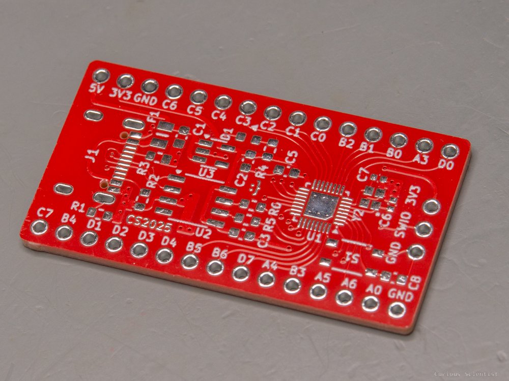
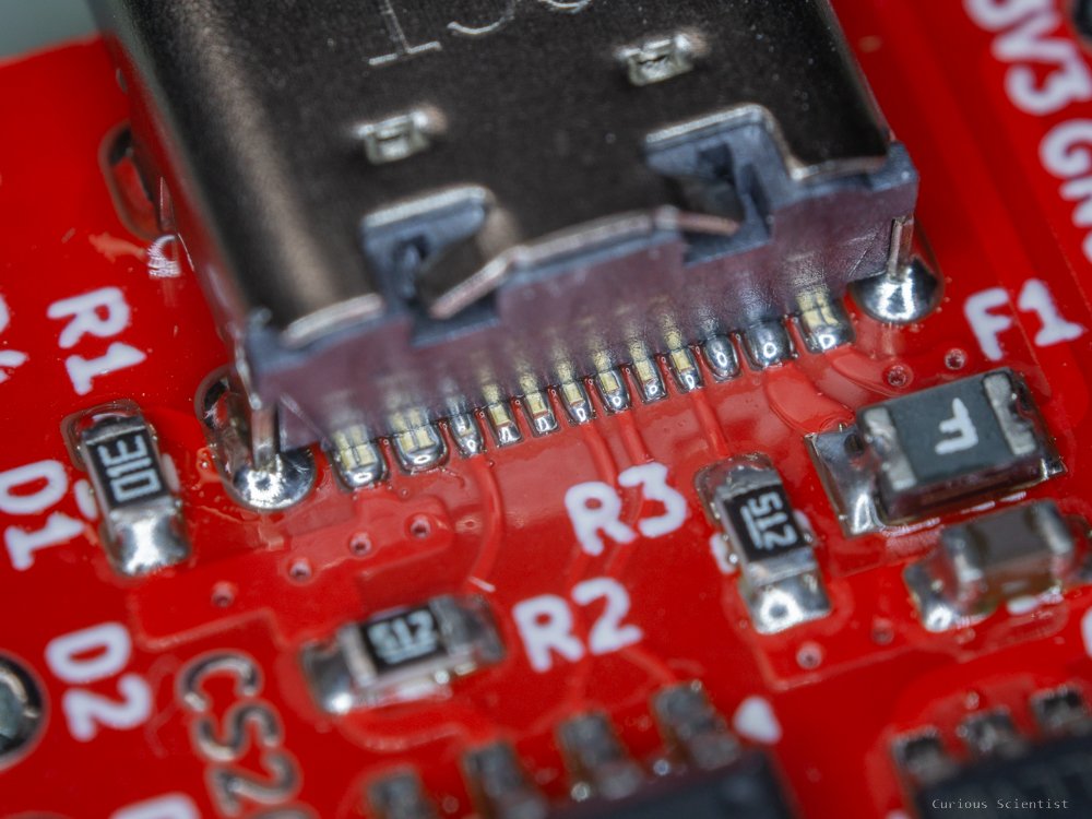
The board is made to be “as small as possible” while respecting my limitations when it comes to PCB design and while keeping in mind that people (like me) might want to assemble these boards at home, by hand. So I used mostly 0603 parts except for the two capacitors for the crystal, which are 0402. The board was made to fit into a regular breadboard while leaving 2 additional rows on each side of the breadboard. It is slightly wider than the Arduino Nano, but it is better for those who suffer from OCD, because the Nano occupies an odd number of rows, so when it is inserted into a breadboard, one side will have 2 and the other side will have 3 empty rows. Life is hard. The USB connector is a regular 16-pin USB-C connector. It is 2025, and we should leave mini USB and micro USB behind and focus on the more modern connector standards.
Finally, as usual, I made the traces curved. People sometimes ask how I do it, so I would like to tell you again that I am using a KiCAD plugin made by mitxela.
Additional resources and pictures
Get the PCB from PCBWay!

If you found this content useful, please consider joining my YouTube channel’s membership or leaving a donation.
Also, please consider using my affiliate links when buying relevant gadgets.
Affiliate links for relevant products: