Custom AS5600 panel for NEMA17 stepper motors
In this video I introduce my new PCB which I designed to fit on the back of a NEMA17-type stepper motor. The PCB contains the basic circuit of the AS5600 magnetic position encoder. It is a very simple circuit which consists of the AS5600 chip, 2 resistors and 2 capacitors. The panel works both at +3.3 V and +5 V. It can be used with i2c or by using the analog output. One very important thing is that if you don’t use the DIR pin, you have to tie it to the ground, otherwise you will have fluctuating readings. This simple circuit board can transfer your stepper motor into a servo, so you can have a precise information on the speed and position of the stepper motor. Or, you can also control the motor using some PID algorithm.
PCB
I designed these PCBs to fit on the back of a NEMA17-type stepper motor, so you can easily turn you stepper motors into a very precise servo or just have a precise feedback from the position and speed. If you want to order these PCBs for your own projects, just click on one of the pictures below and you will be redirected to PCBWay’s website. You will be able to order these boards directly.
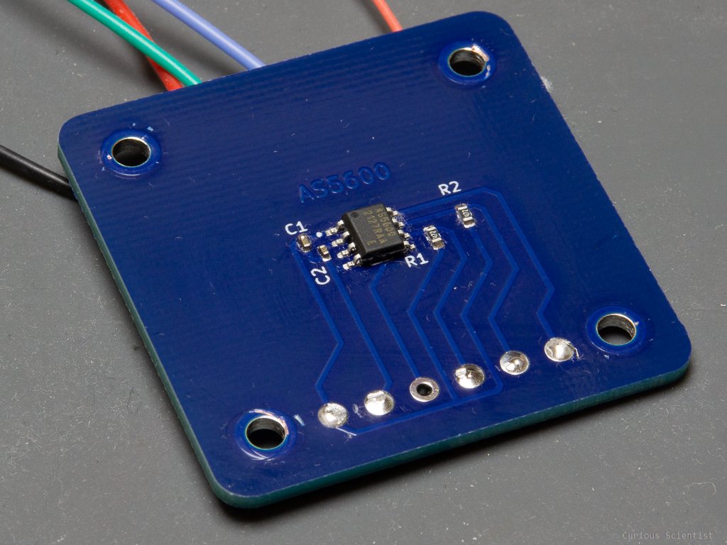
Component side of the board. The dents around the mounting holes are caused by me because I have already mounted the board on a stepper motor and tested it.

Backside of the board with all the necessary connections.
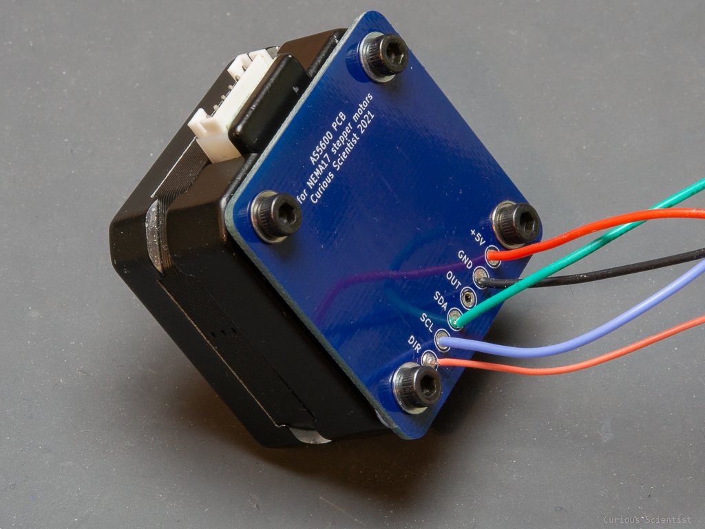
PCB mounted on the back of a thin NEMA17-type stepper motor. Notice that I have an extra wire for the DIR pin. If the DIR pin is not used, it has to be connected to GND!

PCB mounted on the back of a thin NEMA17-type stepper motor. The washers between the stepper motor and the PCB make ensure the proper gap between the magnet and the AS5600 chip.