Motorised Microscope - Computer Software “Update”
In this article, I show you my next improvement for the motorised microscope I have been building and developing for a while. Most recently, the microscope received a 4k-capable camera, and before that, it got equipped with a CNC pendant that allows very precise control of all three axes. So, hardware-wise, the camera is basically finished, and the only thing that was “missing” is a proper software control from a computer. Below, I will introduce my custom PC software that communicates with both the three axes of the microscope and the 4K camera, and it allows me to navigate across the specimen, measure it, take pictures of it and more!
Introduction and refresher
For those who have encountered this article before seeing my other content in the series, I want to quickly go through the recent developments of my motorised microscope.
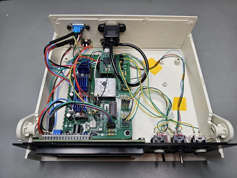
First of all, the circuit I made at the very beginning of the series was already prepared for computer-based control. The onboard Teensy 4.0 was already programmed to receive instructions from a computer and perform them. This was already a conscious design choice: one of the modes that one could select with the 3-way switch, apart from the joystick mode and button mode, was the “USB mode”. The letter “U” on the initial PCB also indicated this mode.
Then, in the new iteration of the PCB, I ditched the button-based control because I found it useless, and apart from a few little improvements, the circuit and the firmware were adapted to control the three axes of the microscope via a CNC pendant. Thanks to the pendant, the stage can be adjusted with micrometre precision, and it is very easy to do so.
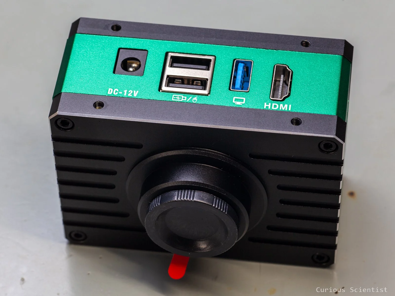
Then, the microscope received a dedicated 4k camera. I replaced my Hawkeye Firefly Split V6 Pro camera with a MaAnt XJ-2. First of all, because I could utilise the Hawkeye camera for better purposes, and I can make amazing close-up footage with it. Furthermore, this dedicated microscope camera allows a larger flexibility when it comes to microscope-related tasks. It even has a built-in operating system that allows me to control the camera with a mouse and perform tasks such as measuring features, drawing shapes, adding text, etc., which can be helpful for microscopy. I made two detailed videos about the camera, in case you are interested.
So, with a complete system: a “CNC microscope” and a high-resolution camera, the next logical step is to control everything from a computer. I can fetch the image of the camera via USB, both in full HD and 4K resolution, and I can send instructions to the Teensy 4.0 microcontroller inside the stage controller circuit to move the stage. Making the controls computer-based allows a more precise control because I can make very precisely determined steps without touching anything around the microscope (so, no vibrations). I can interact with the camera image and instruct the stage to move in a certain direction with a well-defined distance.


The software - Camera controls
The software was written in C# using Windows Presentation Foundation (WPF) as the user interface (UI). Earlier, I developed my apps as a WinForms app. This WinForms is an older UI framework based on a simple drag-and-drop UI editor. WPF is newer and more powerful. It uses XAML for the UI and is much better suited for modern, scalable interfaces. Layout, graphics, resizing, and other actions are much easier to perform with the WPF approach.
The app is split into two main functions: camera-related controls and stage-related controls. I split the window into two regions accordingly. The controls on the left-hand side of the window take care of the camera-related functions. The controls on the right-hand side of the window take care of the stage-related functions. The live image of the camera is located between these two control panels. There is a little strip at the bottom of the window as well. It follows the same logic as the layout of the control panels.
I tried to build the app intuitively. The user should start at the top left corner of the software, under the “Camera Control” text. The first control is a drop-down list. When the camera is connected to the PC, it should appear in this list. After the camera is selected from the drop-down list, it gets connected to the software; however, there won’t be a live feed yet.
We first need to select the video mode in the next drop-down list below. I just implemented the two main modes: full HD and 4K, both at 60 FPS. As I demonstrated in my camera review video, the 4K footage of this camera is not that impressive due to the aggressive compression, so in this video, I will stick with the full HD. It also makes the rest of the presentation a bit easier.
Once the resolution is selected, the camera can be started. Pressing the “Start Camera” button starts the live feed, so we will see the microscope’s image. The controls under it are used to stop the camera (live feed) and to take a snapshot of the image shown in the app.
The app allows the user to take measurements on the image. This is done very simply: by clicking on the image with the left mouse button. The first click places the starting point of the measurement, and the second click places the end point of the measurement. The straight line between these two points is measured in pixel units, and if there’s a calibration available, it is converted into micrometres. A third click starts a new measurement and places the first point of the section onto the field of view. Under the “Camera/app status” section, the point coordinates and the distance values are updated in real time as the mouse is moved around over the image to help navigation. If we want to get rid of the measurement line, we can delete it with the “Clear Measurement” button. Furthermore, we can hide the crosshair from the display as well. The crosshair never shows up in the snapshot images; however, the measurement does.
By default, the measurement just measures the distance in pixel units. But if we want to see the measurements in real units, for example, in micrometres, a calibration must be performed. To further complicate things, the calibration must be performed for each objective lens of the microscope since they have different magnifications and field of views. A pixel-to-pixel distance will be rendered as a different distance in micrometre units. To perform a calibration, we need a calibration slide with known distances, and we need to draw a line along a known length. Once the line is drawn, the user can click on the “Calibration” button and can name the calibration, typically with the name or magnification of the lens. Then, the real length in micrometre units can be entered. Afterwards, the calibration becomes available in the drop-down list under the calibration profiles, and when the proper calibration is selected, the measurement line will show the correct distance, and the scale bar at the bottom right corner will be rendered correctly as well.
I created the calibration profiles for all four lenses in my microscope: 5x, 10x, 20x and 50x magnification. Plus, it is important to mention that these calibrations are only valid for a full HD image feed. For 4K, I would need to do another set of calibration because there would be twice as many pixels between the same points as for the full HD image. So a line with a let’s say 500 pixels length would represent a different distance in millimetres at full HD resolution than at 4K resolution.
Finally, at the bottom left corner, the coordinates of the mouse pointer are shown. These coordinates are scaled to the resolution of the image (and not to the size of the picture box!). So, the top left corner coordinates are (0;0), and the bottom right corner coordinates are (1920; 1080) in the case of the full HD image feed.
Main window with neither the camera or the stage connected to the software
Main window with live image and a line measurement
A snapshot taken from the live feed
The software - Stage controls
The right-side panel is for controlling the stage. First, we need to connect to the microcontroller, which can be done by selecting the correct COM port from the available options in the drop-down list at the top. Once the correct device is selected, the status indicator changes.
At this point, we could already move along all three axes, but the device does not know any of the axes’ locations. Therefore, homing must be performed along all three axes. This can be done at once by clicking the “Home All” button, or one by one by clicking the corresponding button for each axis. The homing on the stage (X and Y axes) is straightforward. In both cases, the stage is driven until the limit switch on the motor side is hit. Then, the motor is driven until the switch is released. This point becomes the zero coordinate of the axis. Then the axis is driven until the physical centre of the axis is reached. The Z-axis is a bit different. Earlier, I showed that there is an additional wire hanging from the Z-axis stepper motor driver, and it is connected to the board separately. There are no limit switches on the Z axis. It uses the TMC2209 stepper motor driver’s sensorless homing feature. The motor is driven so that the microscope head travels upwards until its physical limit is reached. When the rack and pinion hits the end of the rail, the motor starts to stall. This produces excess back EMF in the stepper motor, which is detected by the driver and interpreted as the stalling of the motor. When this signal pattern is detected, the motor is stopped, moved back by a certain number of steps and this position is taken as the zero position. Then the motor is driven so that the microscope head travels a little bit down towards the subject.
Now, after all three axes are initialised, we can move the stage arbitrarily. We can move to an absolute position on any of the axes by entering an absolute coordinate (in millimetres) and pressing the “Move” button for the corresponding axis. I also implemented a simultaneous X-Y motion to make diagonal movements smoother and more efficient. We can also jog the stage. I tried to distribute the X-Y and Z buttons and input fields in a way that makes sense. In the textboxes, we can enter the desired jog distance in millimetre units and then by clicking on one of the buttons, the selected axis will be moved by the previously defined jog distance. The jog distances are relative movements, so the stage is "moved by” a certain distance, and it is not “moved to” a certain location. To make things even cooler, we can right-click on the microscope image, and the controller will pull the clicked point to the centre of the display. The stage will physically move so that the clicked point becomes the new centre point of the image.
Finally, the bottom right corner shows the coordinates of all three axes in millimetre units. They are updated as the stage is moved, and they are getting the values from the stepper motor drivers based on the positions in step units. At the fundamental level, the distances are defined in step units. Then, they are converted into millimetres later. For the X and Y axes, this is done based on the pitch of the lead screws and the microstep resolution of the driver. For the Z-axis, it is done based on the tooth count of the pulley wheels and the microstep resolution of the driver.
Future work
Now, as I am satisfied with both the hardware, firmware and PC software, there are not too many things to do or improve. Sure, it will never be perfect, but not many people can say that they have built their own motorised microscope control system from scratch, both the electronics and the software. So, for me, this is good enough already.
One fun feature I really want to implement is the auto-stitching, or more precisely, capturing the images for stitching. This requires a little hardware and a little software development in the future. Hardware-wise, I want to build a better Z-axis for the microscope. The basic, manual movement of the Z axis is done via a knob that moves a rack and pinion mechanism. I took one of these knob’s shaft and mounted a pulley wheel on it. Then, I drive this pulley wheel with a belt that is connected to another pulley wheel that is sitting on the shaft of a NEMA17 stepper motor. The issue here is that there is a noticeable backlash when I switch direction on the Z-axis. This is not good because the Z-coordinates won’t stay accurate when I move up and down along the Z-axis. So, I either need to improve the belt drive setup or I need to directly drive the Z-axis with the motor, so I can eliminate the backlash that I introduced with the timing belt. (or other suggestions are very welcome!). Or in the very worst case, I would need to replace the Z-axis mechanism with something different that is easier to move up and down without backlash. Maybe a lead screw or a ball screw-based Z-axis would be nice.
The software update for stitching would be relatively simple. First of all, I don’t want to do the stitching part in my software. There is already great software out there for this purpose, and I don’t want to reinvent the wheel. What I want is to capture the images for stitching. So, the implementation of this will be one of the future challenges. And since I am at this point, there is no reason not to implement a Z-stacking feature as well. Similarly to the stitching imaging, I could capture all the images for the Z-stacking and then process them with another, better-suited software. So, I could capture high-resolution and wide depth of field images of microscopic objects.
Stay tuned for the next developments!
Get my PCB from PCBWay!

Get relevant parts using my affiliate links!
If you found this content useful, please consider joining my YouTube channel’s membership or leaving a donation.
Also, please consider using my affiliate links when buying relevant gadgets.