High-performance 3-axis stepper motor control board
In this video, I show you my new development which is a high-performance 3-axis stepper motor control board. It is high-performance because it uses the super-fast Teensy 4.0 microcontroller and it also uses a modern TMC429 stepper motor ramp generator controller together with three TMC2209 stepper motor drivers. The board can be controlled via buttons and a joystick, and I also programmed it to be fully controllable by sending commands and parameters via the serial terminal.
Principles
The board is originally intended to be used for a 3-axis stage setup, for example, as an X-Y stage and Z focus in a microscope system. But it can be used anywhere where 3 motors need to be moved with high precision. The system has three modes.

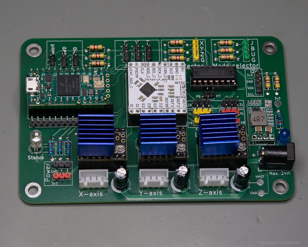
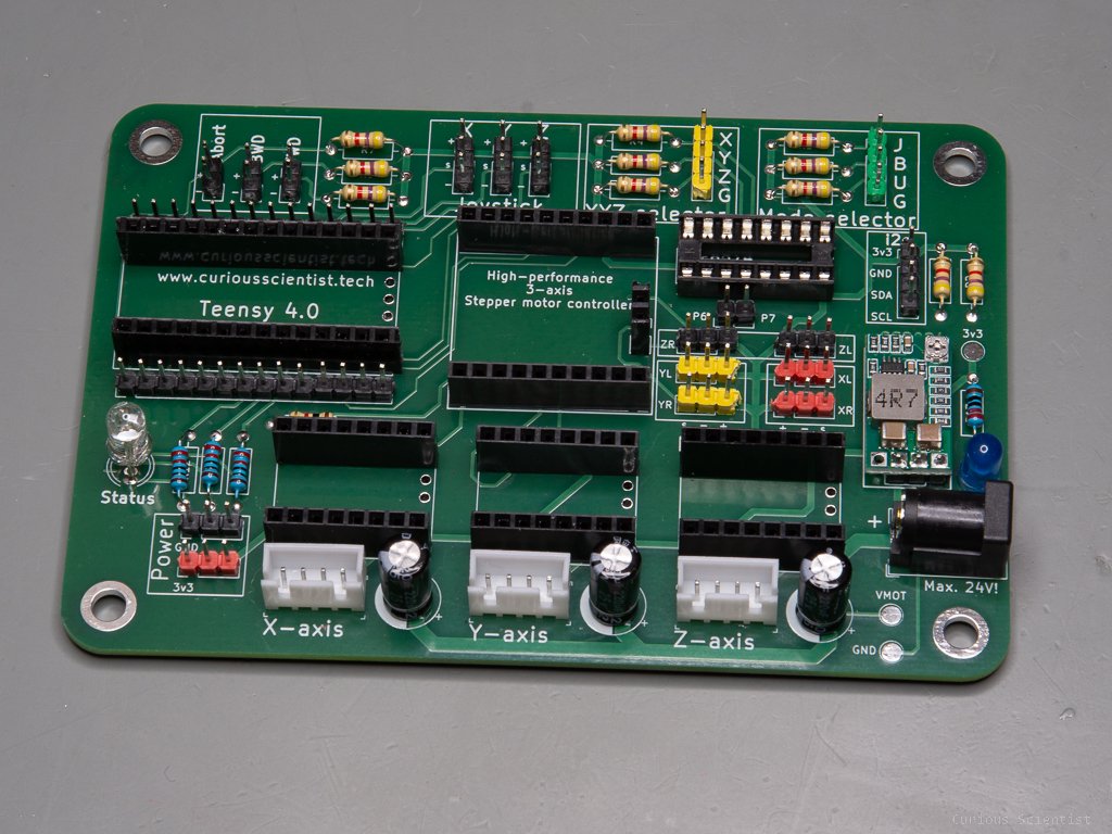
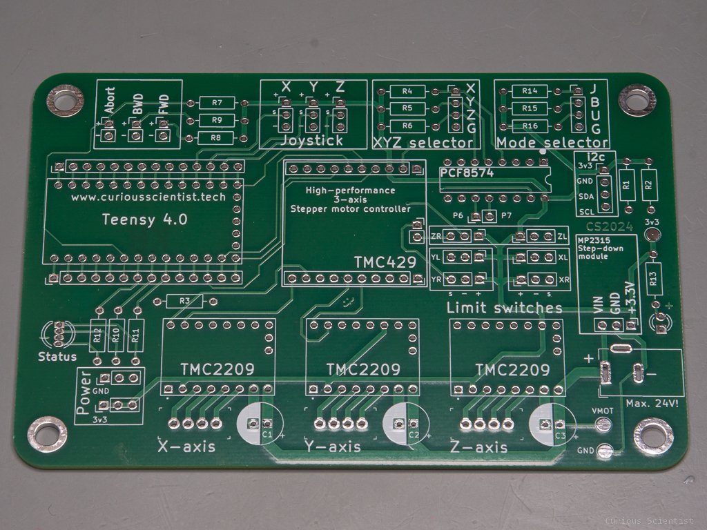
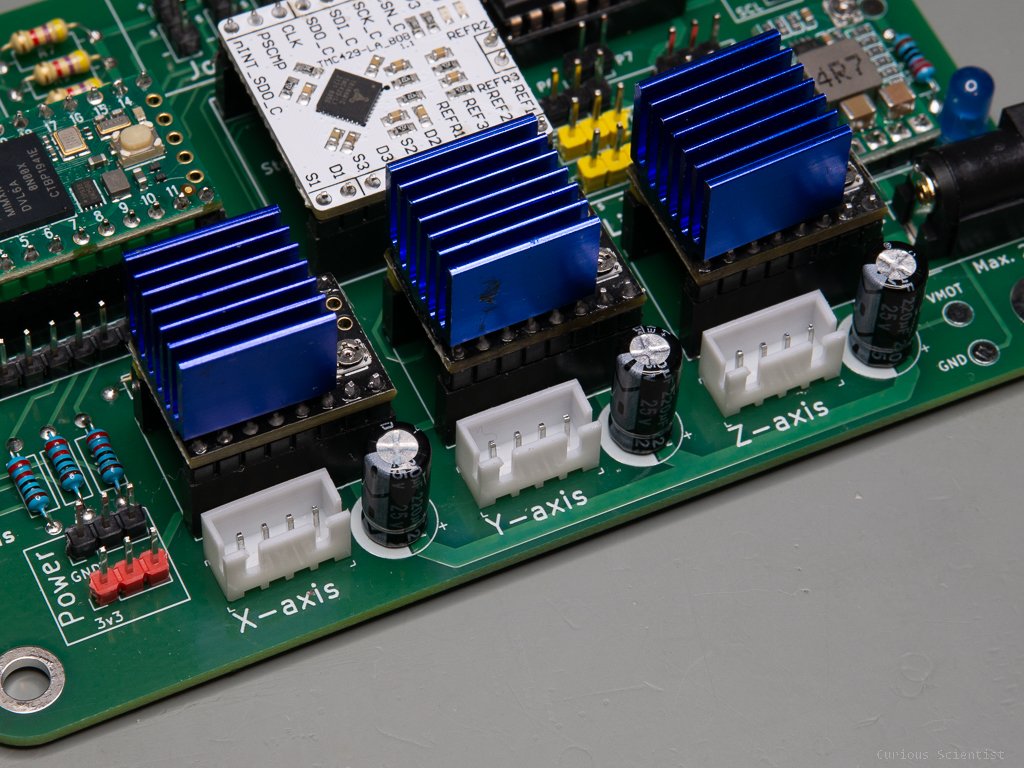
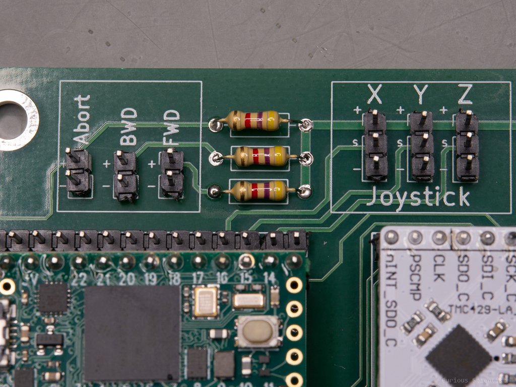
Fully assembled board
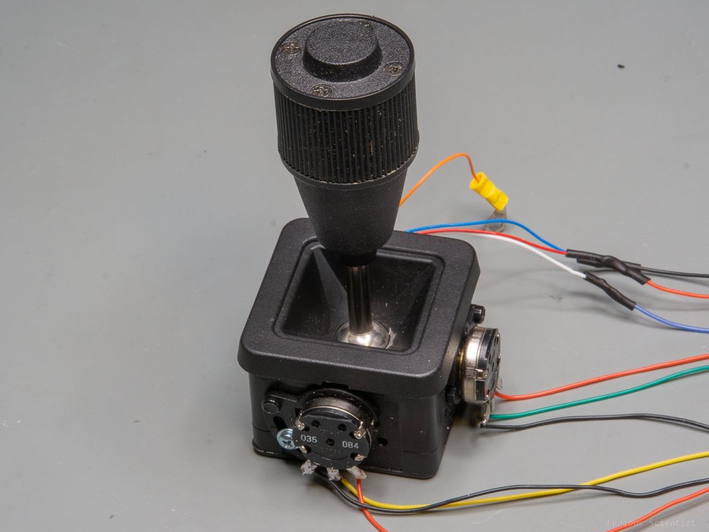
A joystick-controlled mode where the user can control the 3 axes with a 3-axis joystick
A button-controlled mode where the user can select an axis and move it in the positive or negative direction with buttons
A USB-controlled mode where the user can send commands and parameters from the computer to control the 3 axes.
The system has 6 limit switches, where each axis has 2 switches. Each switch acts as a stop switch. If they are hit during the movement of the motor, the motor stops and then it parks. Furthermore, each axis has a switch (in my application, it is set to be the left switch) that acts as the reference/home switch. Upon startup, each motor goes to its home position and parks using the left switch of the respective axis.
The board has an extra header pin set for the i2c bus (SDA0 and SCL0). It is useful for adding external switches. Furthermore, all “regular” GPIO pins of the Teensy 4.0 are available on the board, so if other pins are needed, they can be accessed with a regular Dupont wire. Also, there are some extra 3.3 V and ground pins available on the board in case the user wants to power something.
I want to highlight that this project could not have been so easy without Peter Polidoro’s TMC429 library and TMC2209 library.
Teensy 4.0

Teensy 4.0 microcontroller
I want to mention a few words about the microcontroller. I picked the Teensy 4.0, because it is a very fast and versatile microcontroller. It has enough GPIO pins, but most importantly, it has a lot of memory and a high clock speed. For example, the TMC429 ramp generator board requires an external clock signal. This signal is a 32 MHz PWM signal provided by the Teensy 4.0. The board also has multiple PWM pins, analog pins, i2C and SPI ports which all come in handy in this project. The PWM pins are used for the RGB LED, the analog pins take care of the joystick and the i2C and SPI connections are used to communicate with the other modules. Furthermore, one of the UART ports are also used to communicate with the three TMC2209 stepper motor drivers. The only drawback of the board design is that there’s no easy way of powering the Teensy directly with 3.3 V, so I cannot use it with the PCB’s onboard 3.3 V step-down converter. The Teensy 4.0 is powered via USB.
TMC429

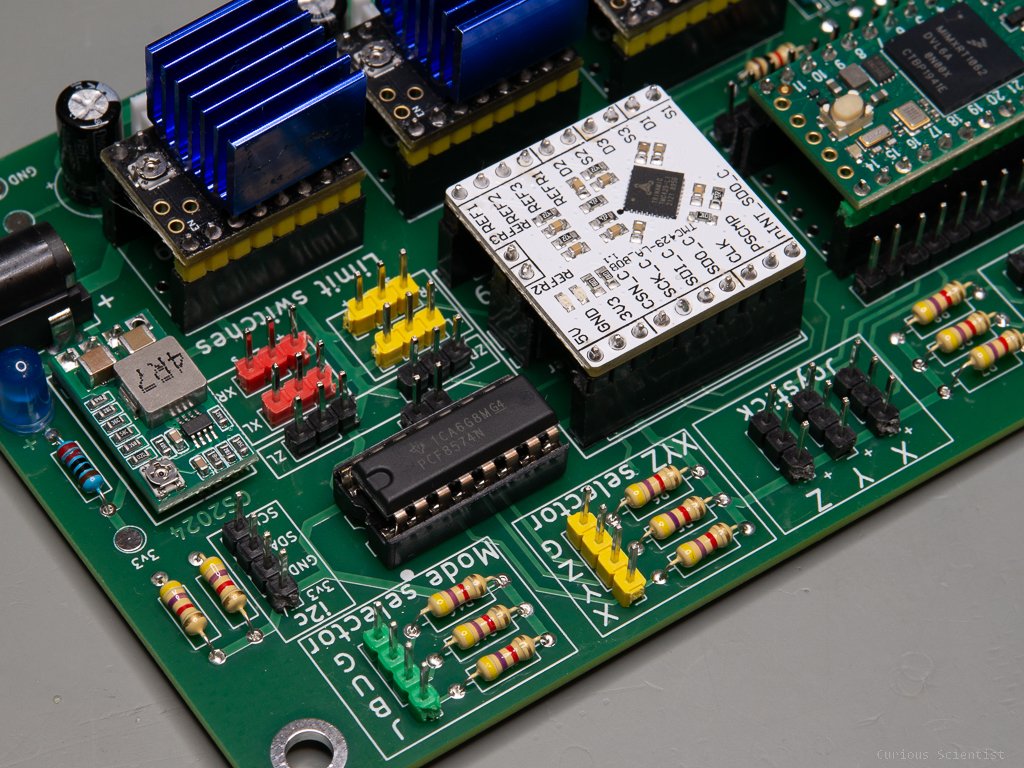
TMC429 Ramp generator
This is a fantastic device that I don’t see being used by other creators. This is a 3-axis ramp generator for stepper motors. It connects to the microcontroller (MCU) via SPI and then it can send the step and direction signals to three stepper motors simultaneously while also taking care of a total of six limit switches (2 per each motor). Its fantastic property is that it totally unloads the MCU because the MCU only has to send a command to the TMC429, and then the TMC429 takes care of everything. It drives the motor according to a trapezoidal speed profile which is configured by the user. It automatically generates the pulses for the step pin and it keeps track of the number of steps being sent to each motor. So, it keeps track of the position of the motors. There’s no need for constantly polling the step pin, or doing expensive maths to generate proper acceleration profiles. After the MCU sent the SPI message to the TMC429, there’s no more load on it.
TMC2209
These silent drivers are absolutely a must for new projects. They are much better than the A4988 or the DRV8825 stepper motor drivers. They have a very smart power management which allows lower power consumption, more silent operation and less heating of the motors. They have an extremely good microstepping which makes them even more silent. They can communicate via UART, so in fact, they could be driven without step and direction signals, at least in simple scenarios.
In this project, I introduced two different modules. One is the original SilentStepStick module and the other is a knockoff module. They are both compatible with the PCB, however, small modifications have to be made on both boards in order to make them work properly. These modifications are shown and explained below.

Knockoff TMC2209
R7 resistor at its default position, UART can be accessed on pin 13.

Knockoff TMC2209
R7 resistor at its alternative position, UART can be accessed on pin 12.

Original Trinamic TMC2209 “SilentStepStick”
The three solder tabs are untouched, UART is unavailable.

Original Trinamic TMC2209 “SilentStepStick”
The centre solder tab connects the UART to pin 12.
After the above-described modifications, both stepper motor drivers can be used. I use the knockoff module in my project because it is 4-times cheaper than the Trinamic module.
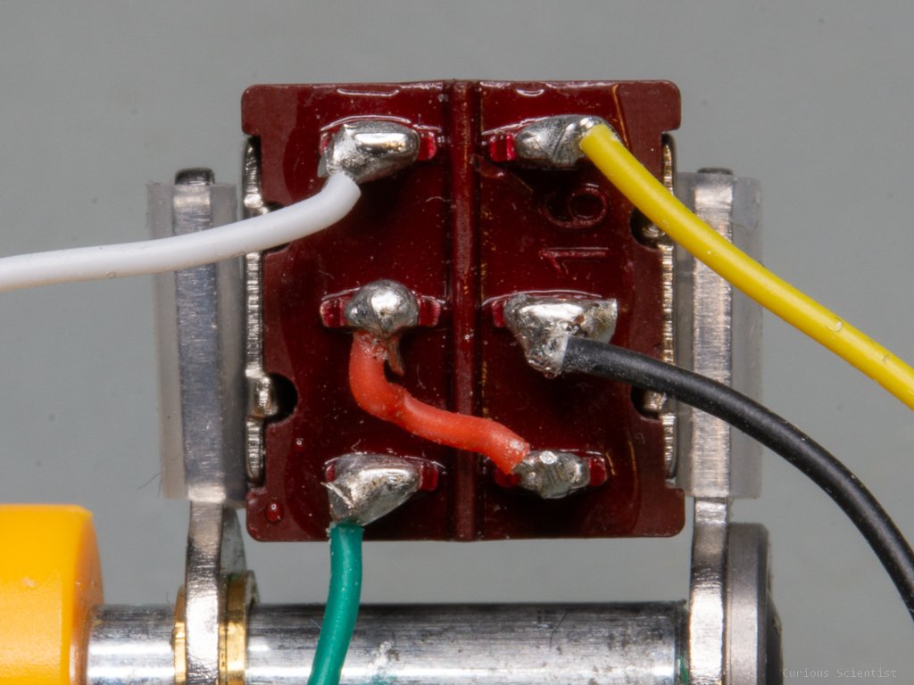
There is one more thing that one must pay attention to which is the difference in the stepper motor pin layout. The original board has M1B, M1A, M2A and M2B pin order. M1A and M2A, and M1B and M2B pairs drive the two coils of the stepper motor. The knockoff module has M2B, M2A, M1A and M1B pin order. I connect the stepper motor to the pins in the following order: black-green-red-blue M2B-M2A-M1A-M1B (knockoff module).
If the different drivers are used with the exact same setup, their behaviour will be the opposite. While one driver will drive the stepper motor clockwise, the other driver will drive it counter-clockwise.

Pin layout of the SilentStepStick (left) and the knockoff (right) TMC2209 modules. One key difference is that the motor pins are mirrored, so while one driver will the motor clockwise, the other will drive it counter-clockwise with the same code. Another difference is that the knockoff module has a CLK pin available. This is unused in the application.
PCF8574

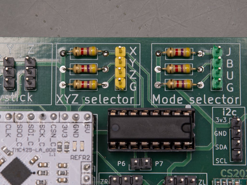
PCF8574 GPIO expander
This is a GPIO expander module. I use it because I did not want to sacrifice six valuable GPIO pins from the Teensy 4.0 These 6 pins are the 2x3 pins for the axis selector and the mode selector switches. They are polled, and there’s no need for high response speed. The chip communicates with the MCU via i2C. As I mentioned in the video, I messed up the routing of the SDA and SCL traces and mixed them, but the shared resources are already revised and fixed. Since the module has a total of 8 pins, the remaining 2 pins were also made available on the PCB. It can be useful if there are some other switches or buttons that need to be read. A suggestion would be a “speed multiplier button”. If one of the remaining pins is active, it would be the “1x speed” option and if the other one is active, it would be the “5x speed” option. So, for example, when the user uses the joystick or the buttons to navigate the motors, it would be easy to quickly change speeds.
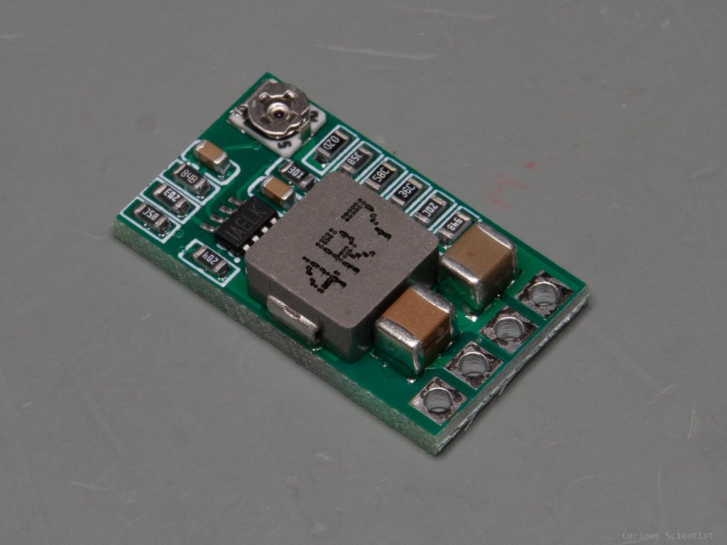
Other features
The board has a few other features which are worth mentioning. All modules an peripherals, except the Teensy 4.0 are powered with 3.3 V. This is supplied by an MP2315-based switching regulator. The switching regulator is capable of supplying up to 3 A current, so in addition to the hardware on the PCB, additional things, such as a display can be powered from the PCB. The voltage for the regulator comes directly from the input DC barrel jack. This terminal also powers the three stepper motor drivers, or more precisely, the motor side of the drivers. On the PCB, I put a status LED next to the voltage regulator so the user can easily see when the 3.3 V is available on the board.
Another fun feature is the RGB status LED. I used a PWM-driven, common-cathode RGB LED to indicate different statuses of the operation of the board. The board can signal if something is not working properly by changing the color and the behaviours (solid light or blinking) of the LED. This feature is useful when the board is used without any displays or any communication with a computer.
The board is also equipped with M4 mounting holes at the corners. This can help to attach things to the board or fix it in an enclosure.
Other resources
Please buy the relevant parts using my affiliate links!
Join my YouTube membership!
Get my PCB from PCBWay!