Bird camera - Raspberry Pi Zero 2 W
In this article, I show you how I built my own Raspberry Pi Zero 2 W-based bird camera. The project consists of a lot of different techniques, which makes it interesting to build. It requires some electronics knowledge, some CAD and 3D printing knowledge and a little bit of woodworking. The result is a fun remote bird feeder with high-resolution live feed.
Introduction
I am getting more and more birds around the house. There are a few feeders around, but I can only take pictures from the inside through the windows. This does not always result in a good picture due to unwanted reflections and other issues. Therefore, I wanted to build a bird feeder that has a built-in camera. Sure, there are off-the-shelf devices on the internet for this exact purpose, but making my DIY version allows me to learn new techniques and have full control over my device. No subscriptions, no weird cloud services or other similar things. Actually, if I stop for a moment to justify my build, I could perhaps even say that my camera-related setup is cheaper (approx. $60) than the off-the-shelf competitors. Perhaps some features are not that excellent, but I will discuss these details below.
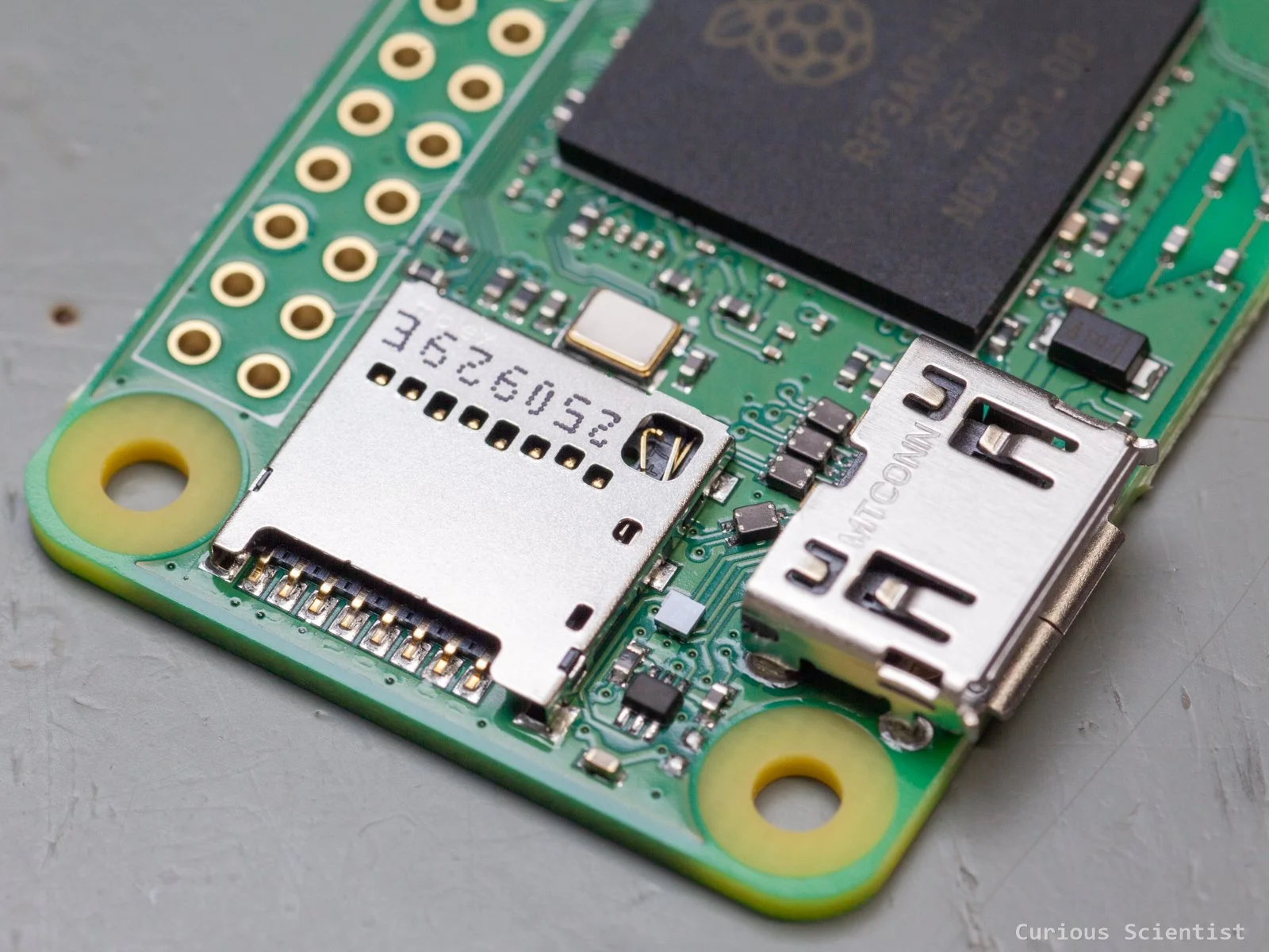
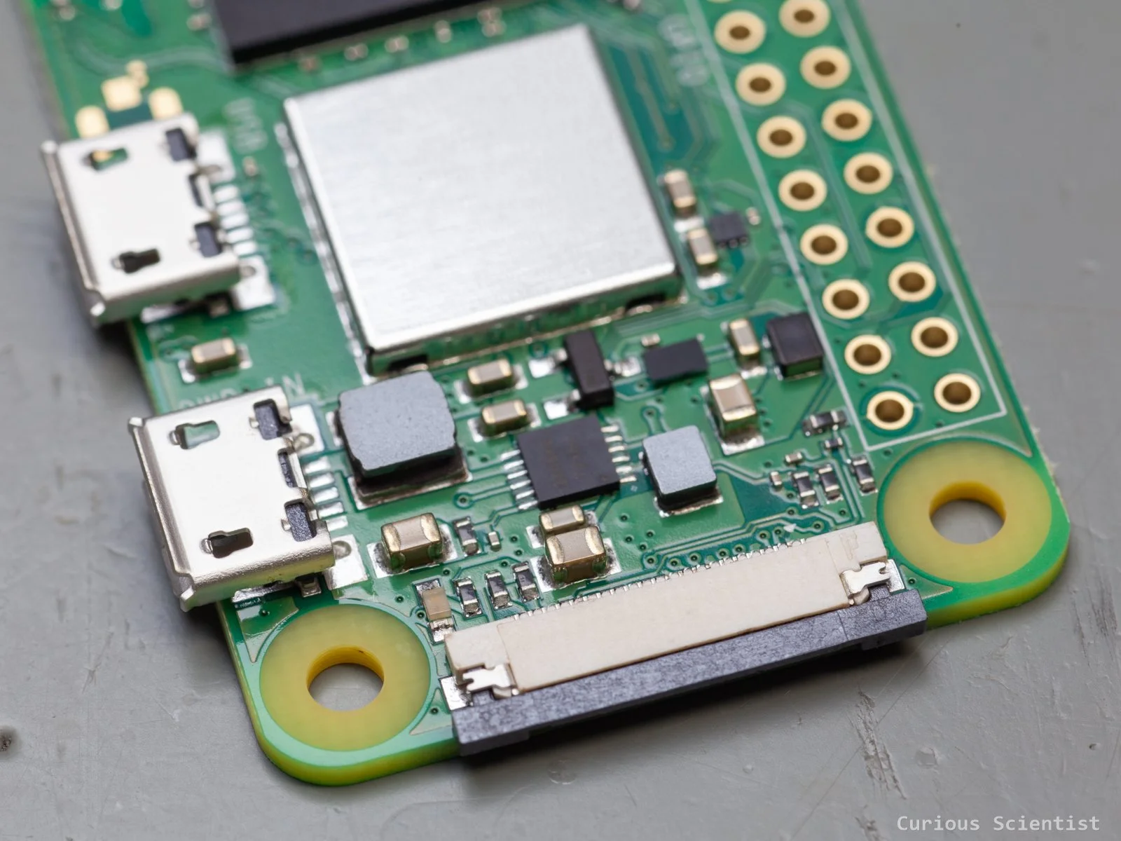
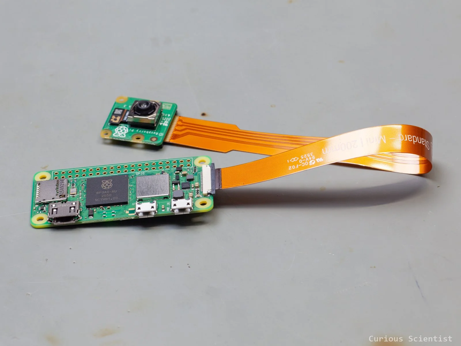
The core of the device is a Raspberry Pi Zero 2 W microcomputer and a Raspberry Pi Camera Module 3. The Pi is a powerful little device with a processor clocked at 1 GHz and 512 MB RAM. It has built-in wireless connectivity, an SD card slot, a micro HDMI port and plenty of GPIO ports. It is a really powerful device, and it is so popular that my local electronics store has limited stock, and one can only buy 1 unit per purchase. I saw other creators around the world talking about supply issues, too.
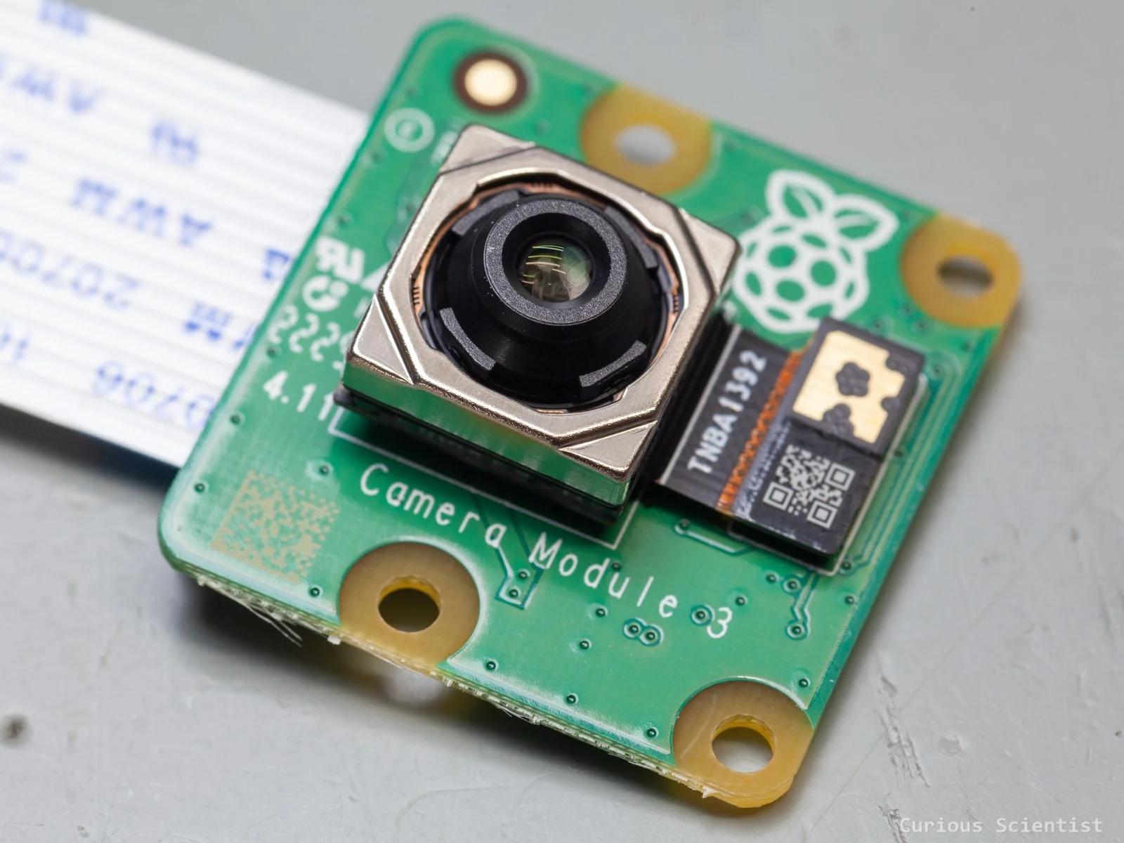
The camera is a 12 MP autofocus camera based on a Sony IMX708 sensor. It is able to record 1080p footage at 50 FPS or take still images at 4608 × 2592 pixels. With proper software, we can utilise the camera very well.
So, the camera and communication will be managed by the above devices. However, the device must be powered somehow, and we must keep in mind that it will be sitting outdoors!
Battery-only operation is not really an option because I don’t want to change and charge batteries often. Direct power supply via a power adapter is not an option either because I do not have any outlets around the house where it would make sense to place the feeder.
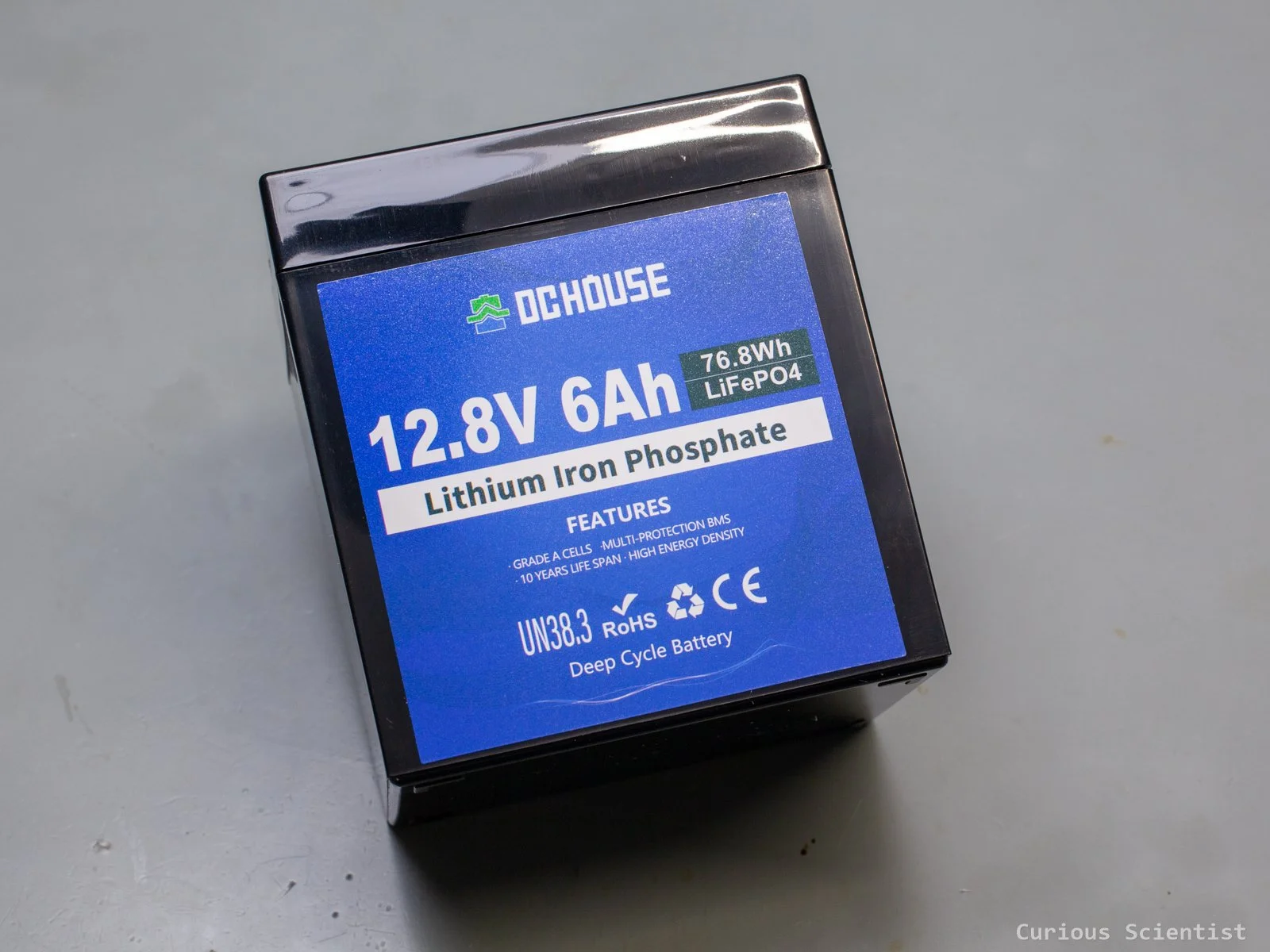
Therefore, I decided to finally start getting some experience with solar panels and battery chargers. It is a bit overkill perhaps, but the system will be powered by a 12.8 V 6000 mAh LiFePO4 battery, which is managed by a 12 V 10 A PWM solar charge controller. The solar panel is a 25 W 12 V monocrystalline panel.
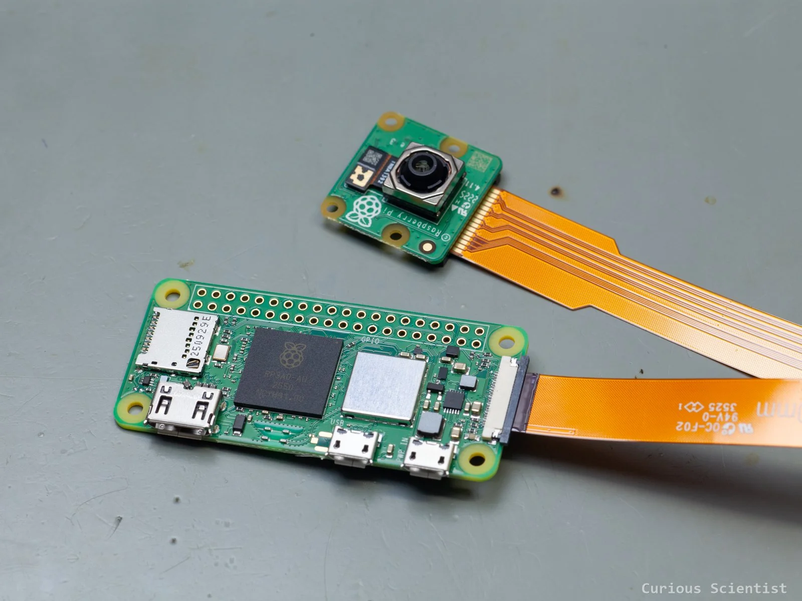
Raspberry Pi Zero 2 W and Raspberry Camera Module 3
Building the camera
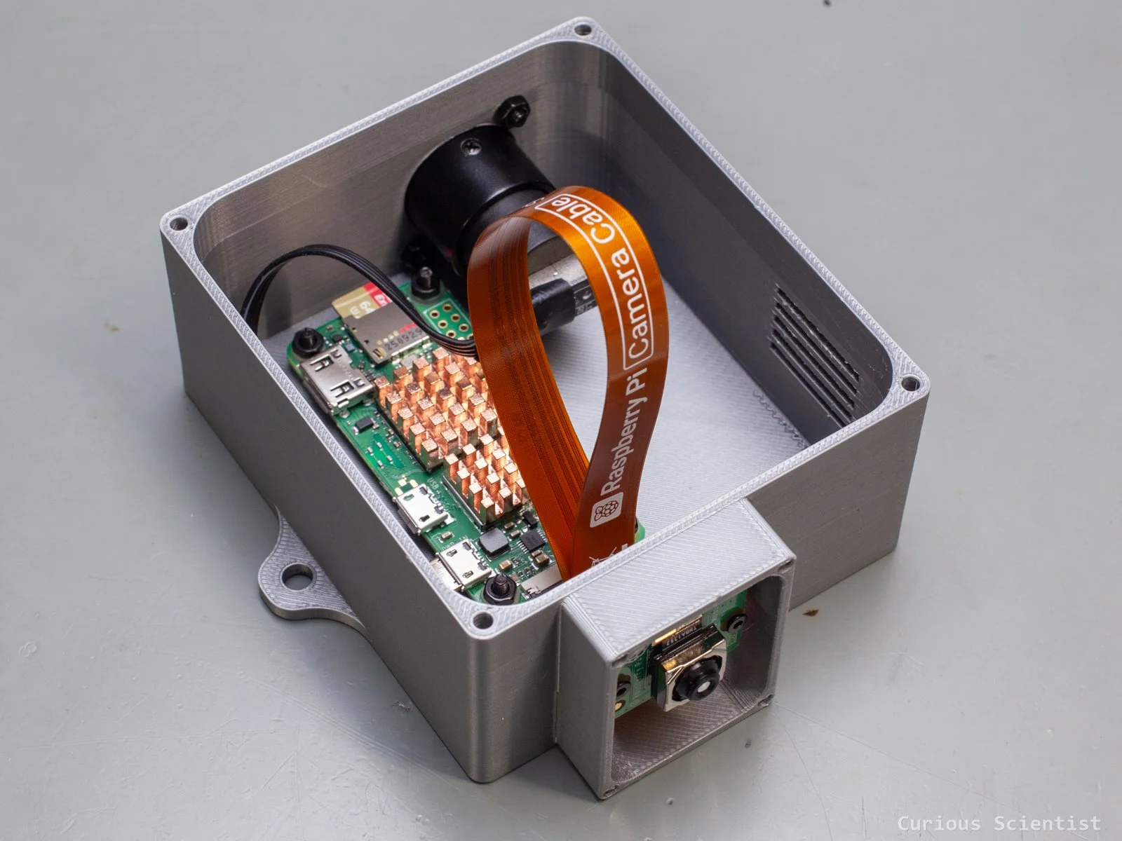
First, let’s talk about the electronics. This is fairly simple. We have the Raspberry Pi and its camera module. They are connected to each other via a long and flexible ribbon cable. They will be placed in a 3D printed enclosure that consists of three parts: a main enclosure, a lid and a shield for the camera module. Hopefully, this will provide enough protection against the environment and bugs. Then, the power somehow must be supplied to the board. This is done through a USB panel mount connector.
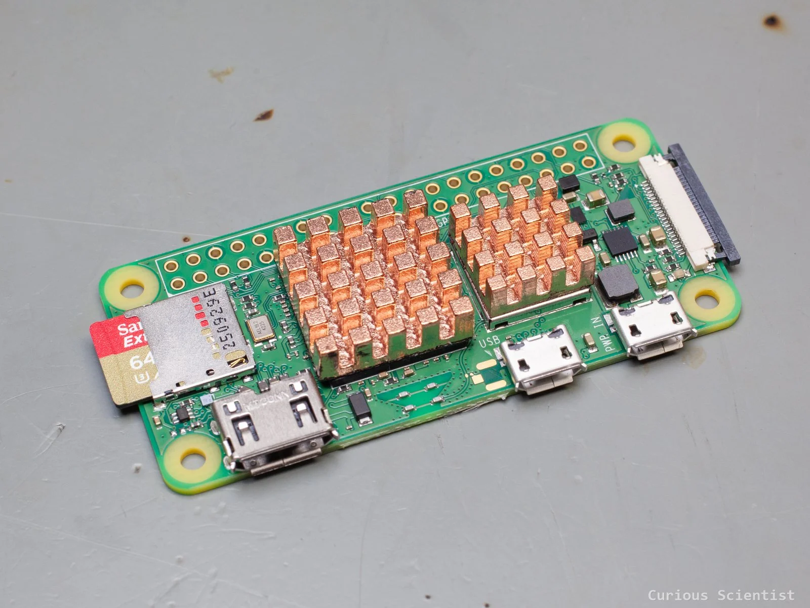
The Raspberry Pi received two copper heatsinks to help with better thermal management. The weather in Sweden is rather mild even during the summer, so it might survive even without these when it is used outdoors, but if a cheap component could improve the operating conditions of the device, then why not use it!? And there is a 64 GB memory card inserted into its SD card slot for the operating system and other stuff.
The camera module does not require too much explanation. It has a built-in autofocus motor, which will come very handy during use. The module is small, and it has four nicely prepared mounting holes, so it will be easy to fix it in the enclosure.
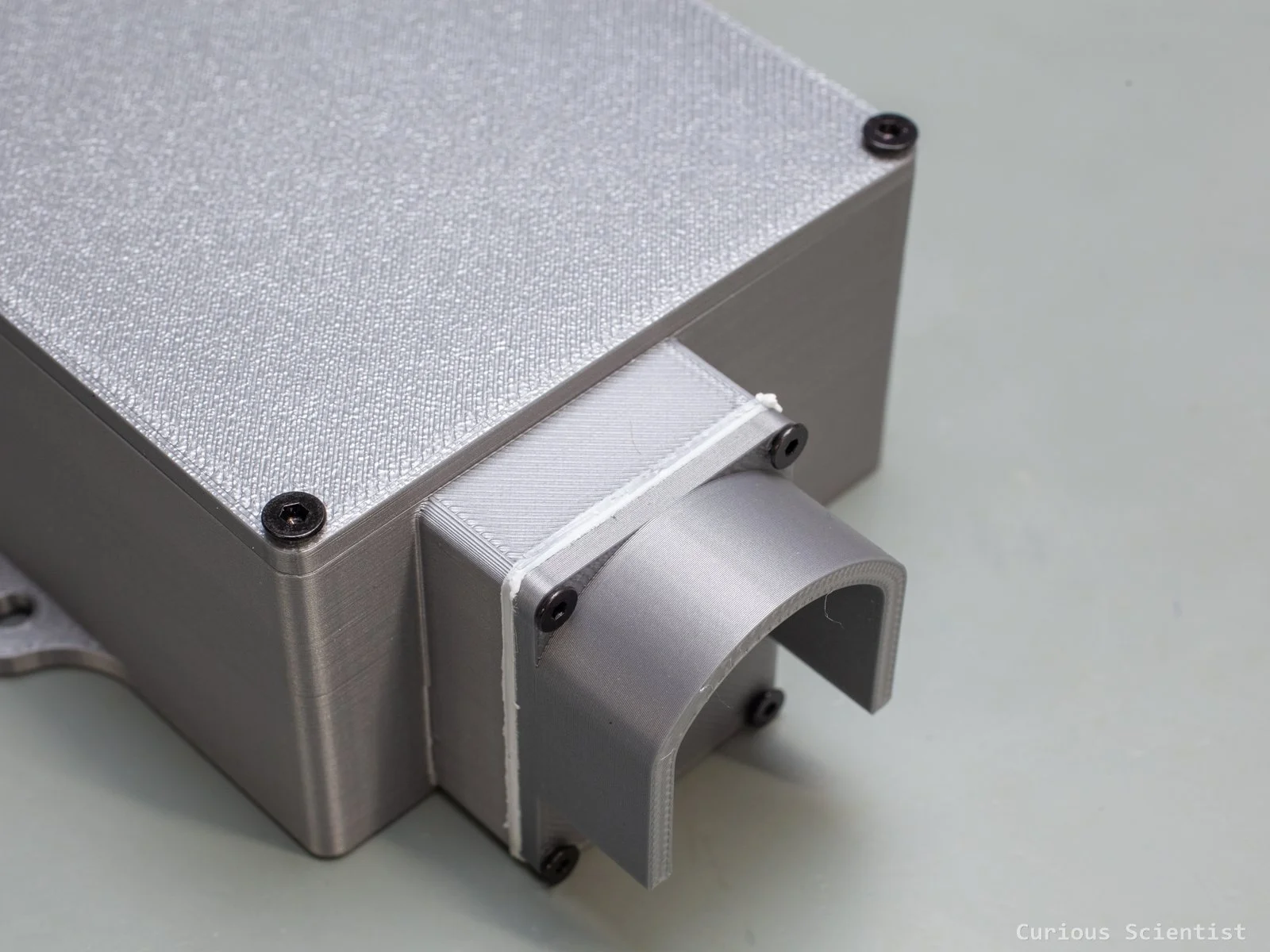
Perhaps a more interesting part is the USB connector. It is a simple USB 2.0 panel mount connector with female ports on both sides. It only needs two screws to fix it to the enclosure. This connector allows a nicely sealed connection between the enclosure and its contents and the external power supply. Inside the enclosure, I use a flexible male USB A-to-micro USB cable. This connects the panel mount connector to the Raspberry Pi and provides power to it.
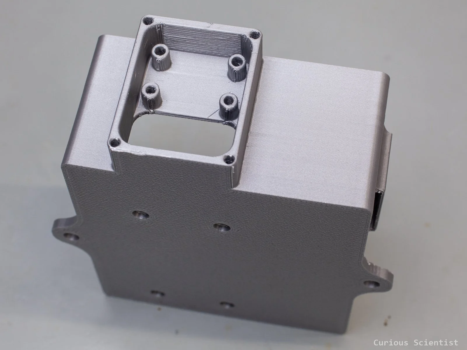
So, the above components are squeezed into a 3D printed enclosure. It is printed with PLA. It won’t be exposed to direct sunlight and direct moisture because it will be placed in a wooden shelter, so the UV light and rainwater are not a concern. I created mounting holes for the Pi. I took the connectors and their positions into consideration, so everything fits nicely, and it is relatively simple to assemble the box. At the bottom of the box, the screw holes are sunk into the base, so the flat-headed screws entirely disappear. This allows me to keep the bottom of the enclosure flat, which makes it easier to mount it. The Pi is held by the four columns and the four screws. To be on the safe side, I put washers between the board and the nuts as well.
The camera module also has its seat with four screw holes. The holes go through the whole enclosure, so there is no need for insert nuts or similar stuff. Just use a long enough screw and a nut. I also put a large opening under the mounting of the camera, so the ribbon cable can be tucked in nicely. Actually, the whole camera module can fit through the hole, so we do not need to fiddle with the ribbon cable when mounting the camera.
The camera module is protected by a shield. This shield is screwed directly onto the front side of the camera’s seat. I did not bother adding extra material for insert nuts, but instead, I designed slightly undersized holes for the screws, and before screwing the screws in, I added a drop of thread locker glue in each hole. The combination of these two things should provide a good enough connection. The front shield is just a piece of plastic; it is not a load-bearing element, so it is totally unnecessary to waste insert nuts and extra printing material for this purpose, in my opinion. The hole in the shield directly exposes the camera’s lens. There is no protective glass or anything in between.
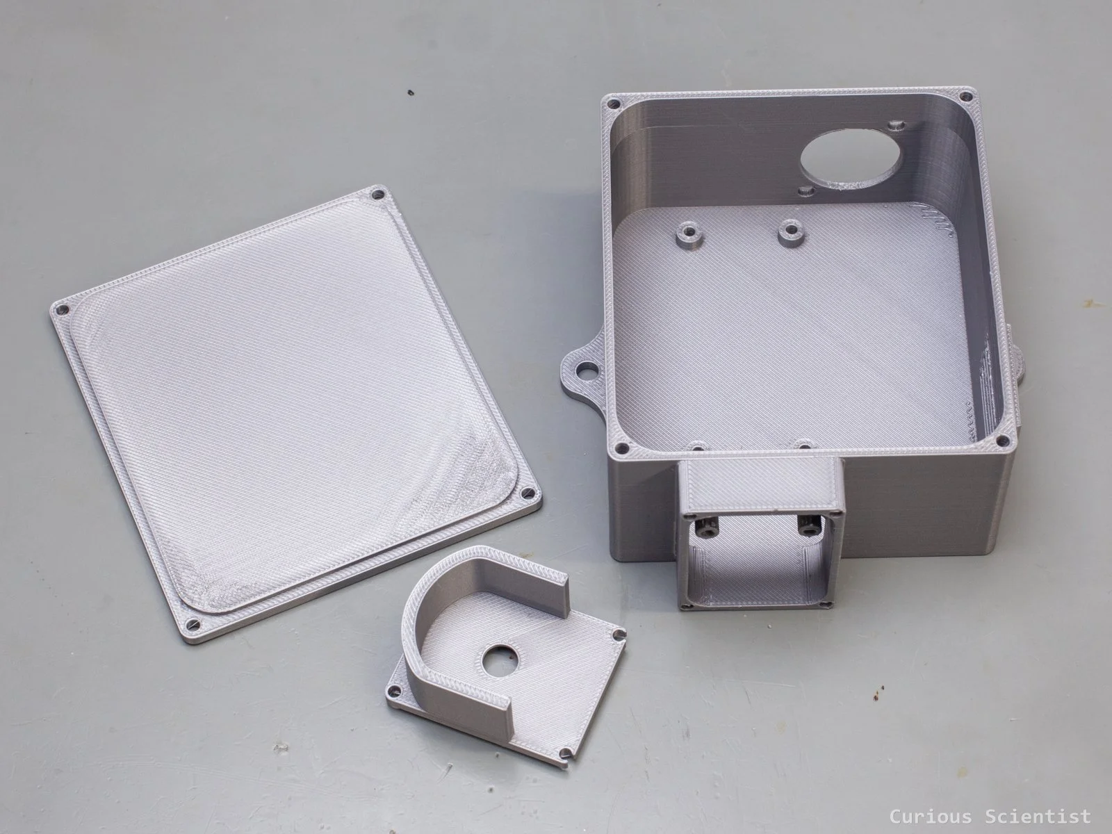
To make sure that the condensation, which can happen with enclosures placed outdoors, is not an issue, I made a little vent for the enclosure. A few slits, sheltered by a cover which allows a limited airflow between the environment and the inside of the box. Hopefully, it is enough to avoid moisture condensing on the electronics. Finally, the top of the box is sealed with a lid. It received an edge that hopefully provides a little better sealing. The lid is attached to the enclosure with the same technique as the shield for the camera module: I used slightly undersized holes for the screws and put a drop of thread locker glue in each hole. The lid will stay on the enclosure, I am fairly confident.
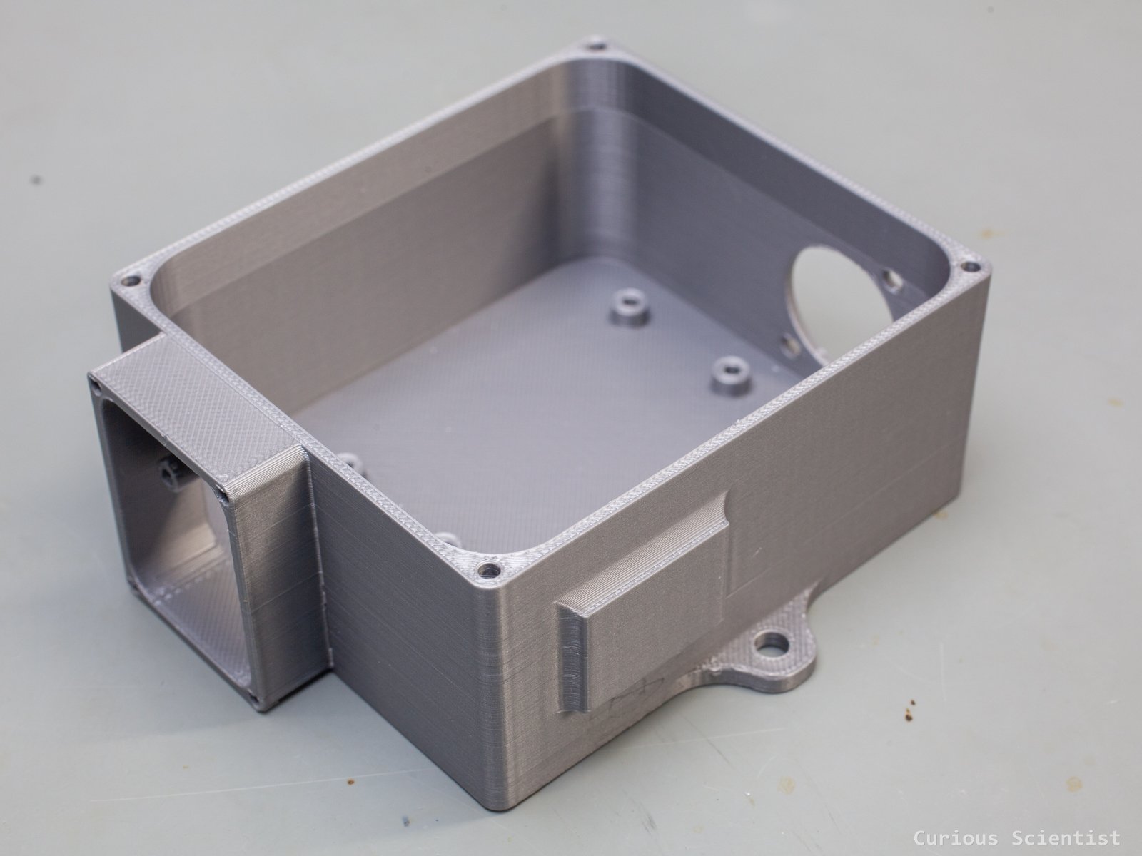
Empty enclosure without the lid and the camera shield
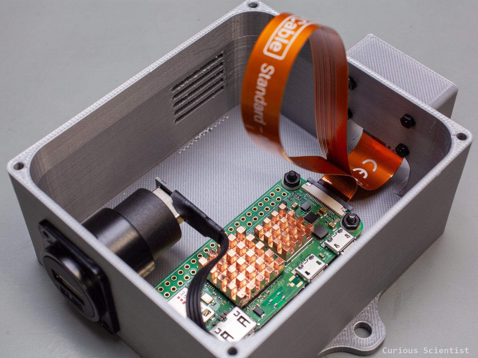
Populated enclosure. Still without lid and camera shield
Preliminary testing and preparation
To see what we can expect when it comes to operation and power consumption, I had to test the camera before placing it outdoors. With the help of my USB tester, I could test the setup’s power consumption during booting, idling and streaming.
I used a software called CamUI to stream the camera’s image. More about this software will be shown later! The main conclusion is that during streaming, the current consumption is around 400 mA, and during idling, it is about 300 mA. Actually, the streaming service can be (and will be) shut down to further decrease the power draw.
But anyway, I have a 12.8 V 6000 mAh battery. According to a quick, back-of-the-envelope calculation, this is about 77 W “capacity”. The Pi consumes about 2 W (5 V x 0.4 A) per hour, so it would take about 38 hours to fully drain the battery while streaming.
However, I won’t stream all day long; I even shut the service down automatically between 22:00 and 07:00. Plus, during spring/summer, when I eventually use the camera, the sunlight hours are so long that the battery is almost always kept at maximum charge by the solar panel.
As I mentioned, the 3D printed enclosure will not sit directly under the sun, and it will not be exposed to rain or other things. I made a wonky little shed for the camera’s box. I used a few OSB sheets, screwed them together, then filled up the gaps with some caulk and finally painted the whole thing white. Since this type of panel does not really like moisture, I put a plastic sheet on the roof and on the feeder area to make it a bit more weatherproof. My woodworking skills are literally zero, so this is the best I could do for now. But with this preparation, the module is ready to be used outdoors.
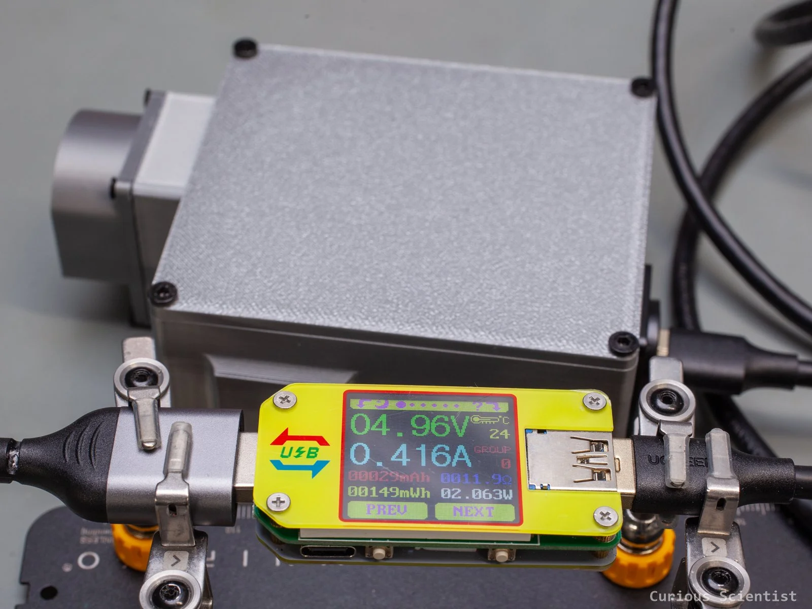
Camera’s power consumption at peak
Power management
Let’s talk about the power management of the device a bit more. I briefly showed and mentioned the components already, but I want to show the whole system, so others can replicate it.
First, everything is placed in a plastic enclosure designed for outdoor usage, and as an extra, I made a little roof for the box using some wonky OSB sheets. The sheets were not treated when I recorded the footage, but later, they received a few layers of wood oil because they are not really made for outdoor use. But this is what I had available.
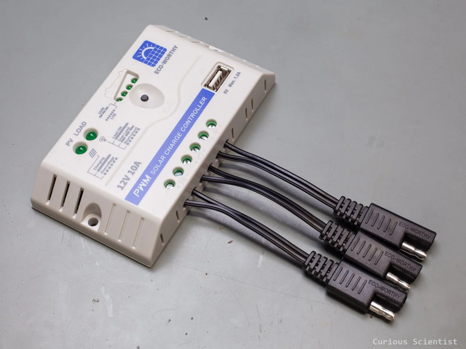
Starting from the top, we have the 12 V 10 A PWM solar charge controller. This device takes the generated electricity from the solar panel and distributes it towards the battery, the onboard USB port and the 12 V output for loads such as lights or basically anything that can be driven from a 12 V power source. The device has multiple indicator LEDs. It can indicate whether the solar panel is generating electricity and if the output is enabled. Plus, the four smaller LEDs towards the centre can be used as the charge indicator of the battery and as the program indicator. We can select the type of battery connected to the device, and the selection is made based on the LEDs’ state.
At the bottom of the device, there is a USB port that can supply 5 V and 1.2 A. This is perfectly enough for the Pi, so I use this port to power the Pi. An alternative solution would be to use the charge controller’s 12 V output and use a DC-DC converter to provide 5 V, but I found this option a bit risky and cumbersome. So, I just went with the built-in USB port, so I just need a long USB cable, and that’s all.
Below the charge controller, there is a little 12.8 V, 6 Ah LiFePO4 battery. It is small, lightweight and can store enough power so that my device can run for a while, even on cloudy days. I connected an external battery monitor device to the battery to even see the voltage of the battery. This helps me to see if the voltage levels are OK. I also put a small thermometer in the box. This will be more useful during sunny days to see how hot the box becomes. But it can even help me to see if the humidity is too high in the box.
And finally, the solar panel. The panel is about 42 cm × 30 cm, and it has a steel frame for mounting. The frame, depending on how it is attached to something, can be rotated, but what is probably more important is that it allows the panel to be tilted. This could help us to maximise the absorbed solar power and improve the charging of the battery.
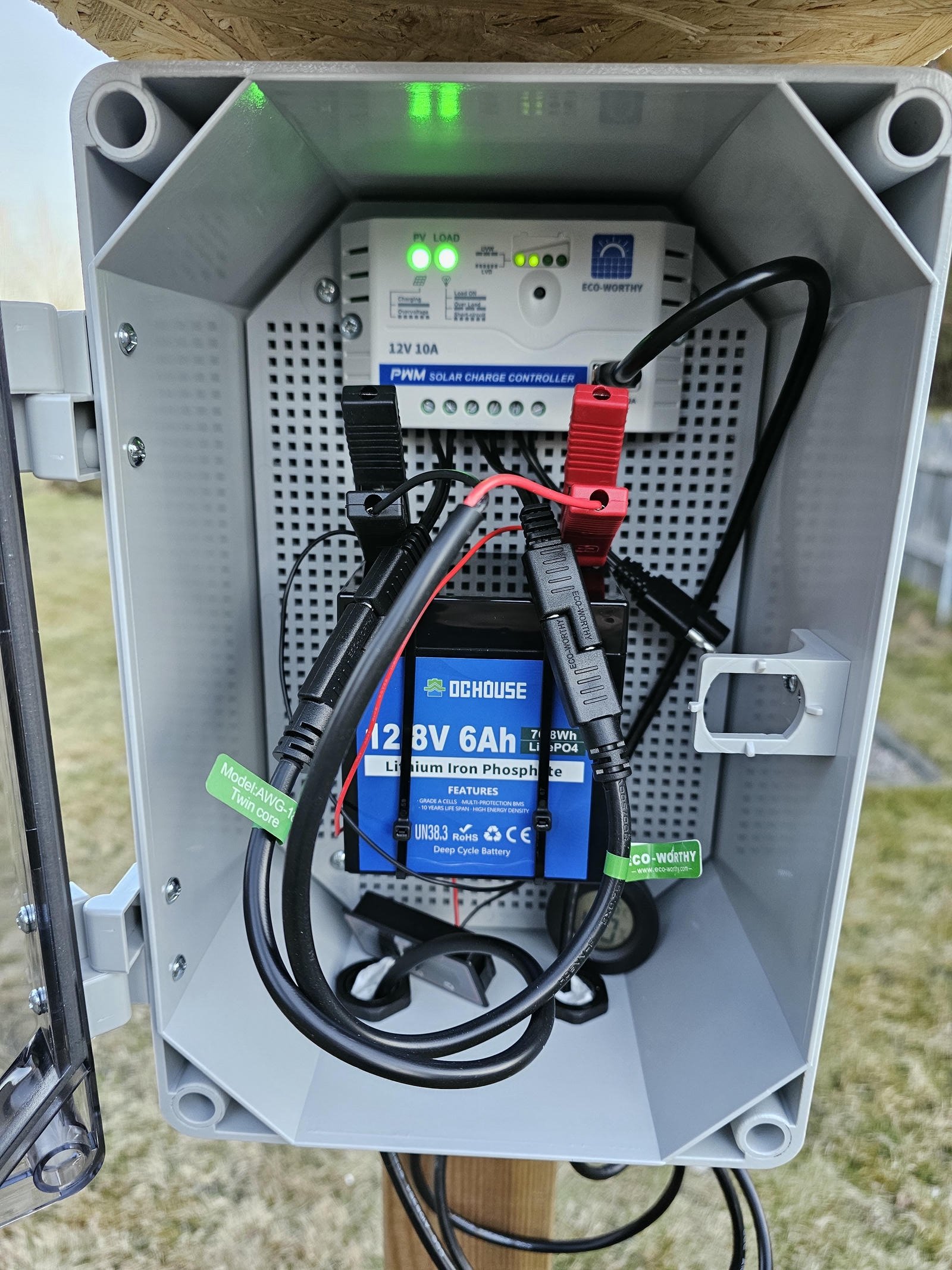
Power management with the PWM charger module and the battery. Encapsuled in a weatherproof box.
Field tests
During the first trials, I put the whole kit on an unused outdoor drying rack. This was a good test to test the system, but I could not capture a single bird. The drying rack was too exposed, and all the birds avoided it, despite the fact that the garden was full of birds otherwise. Nevertheless, everything seemed to work well. The enclosure held up nicely. I did not detect any moisture despite the fact that during certain days it was freezing during the night, and then it was nearly 15°C and sunny during the day. The battery was kept near its full charge and the camera has no issues with power. The only thing I noticed is that at this distance, the Pi sometimes had connectivity issues. But this is perhaps due to the distance between the camera and the router, which is about 15-20 meters.
So, after realizing and accepting that the drying rack won’t attract birds, I relocated the camera. As I mentioned, I already had a few feeders around the house, so I decided to put the camera close to one of these feeders because the birds were already there. This needed a little planning because the solar panel became less exposed and the camera had to be mounted on a tree. I figured both these issues out and I managed to find a solid place both for the solar panel and its electronics and the camera. The only “issue” was that now I needed a 5 m long USB cable to provide power for the camera.
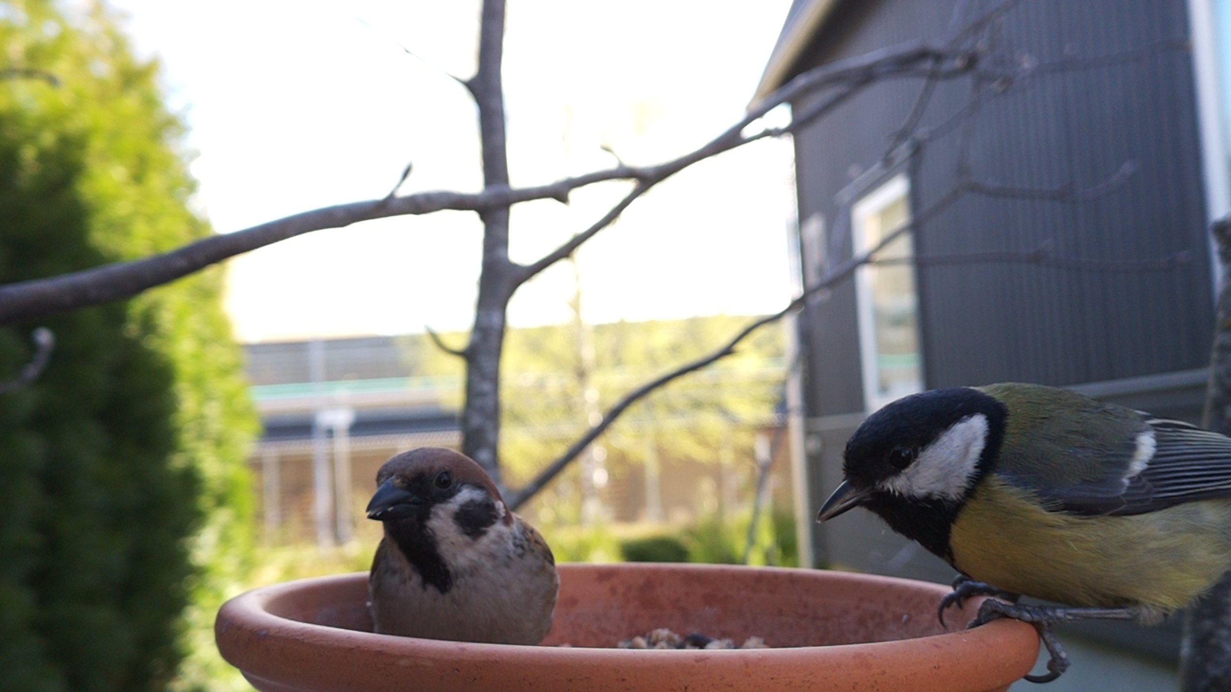
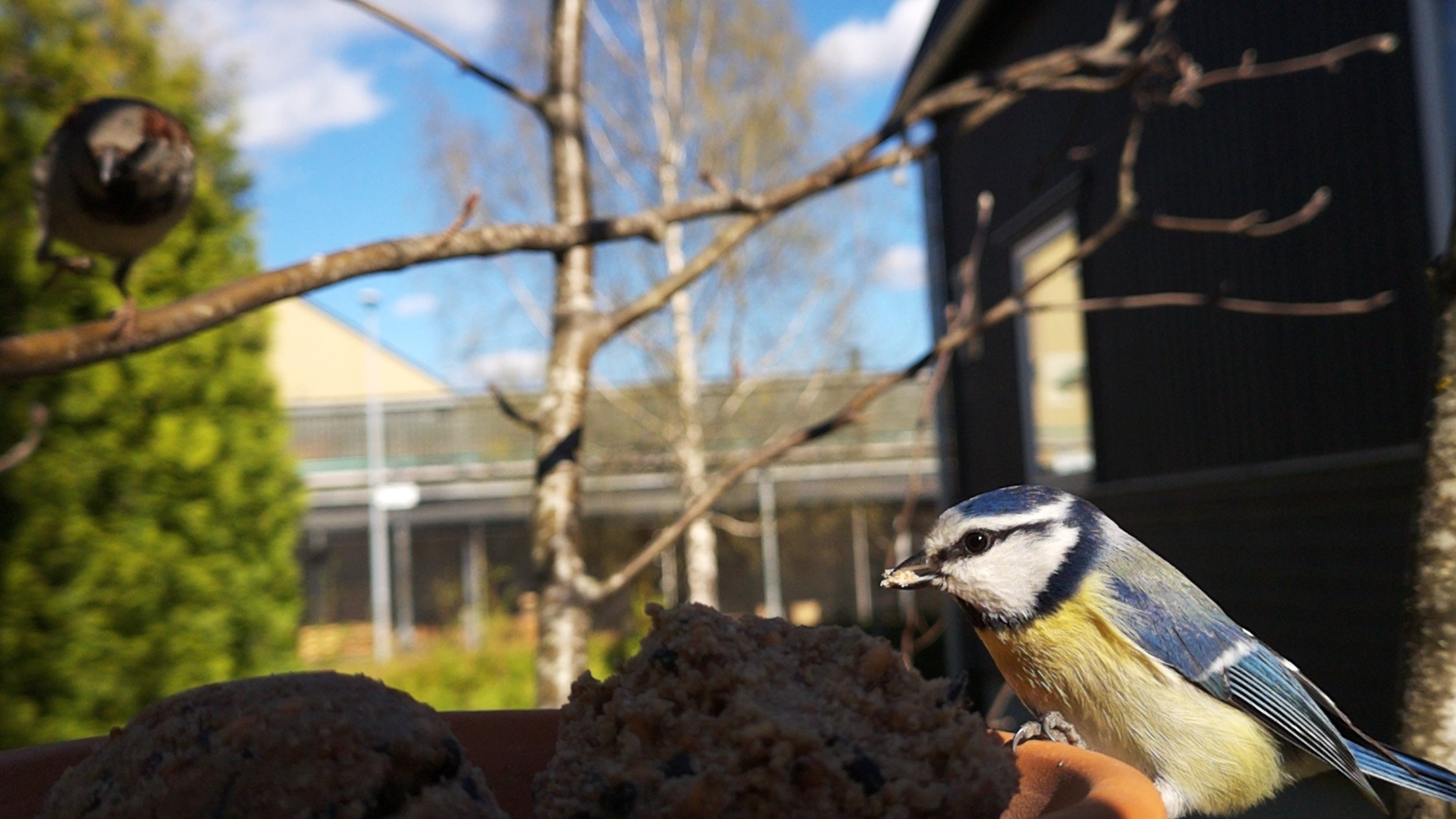
Once the camera was in place, the birds showed up in two minutes. I placed the camera so that both the feeder plate and another feeder are in the field of view. Some birds prefer the plate while others like the other feeder which is filled with balls of fat and seeds.
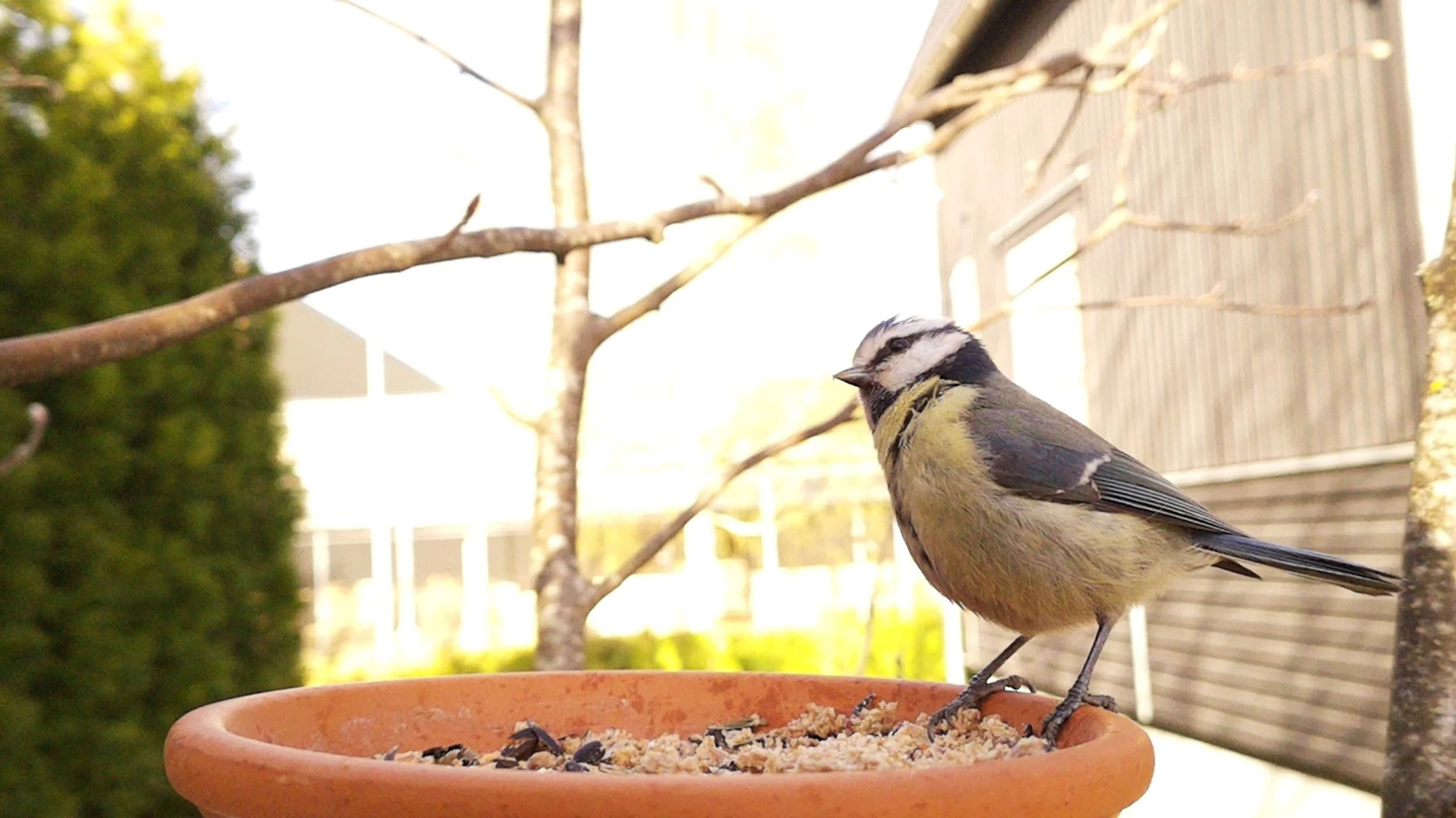
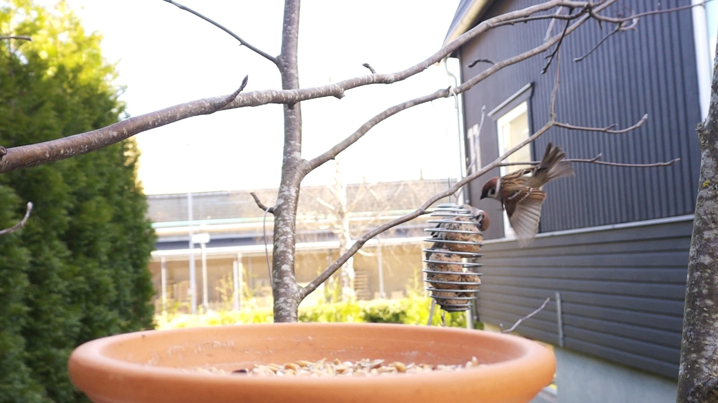
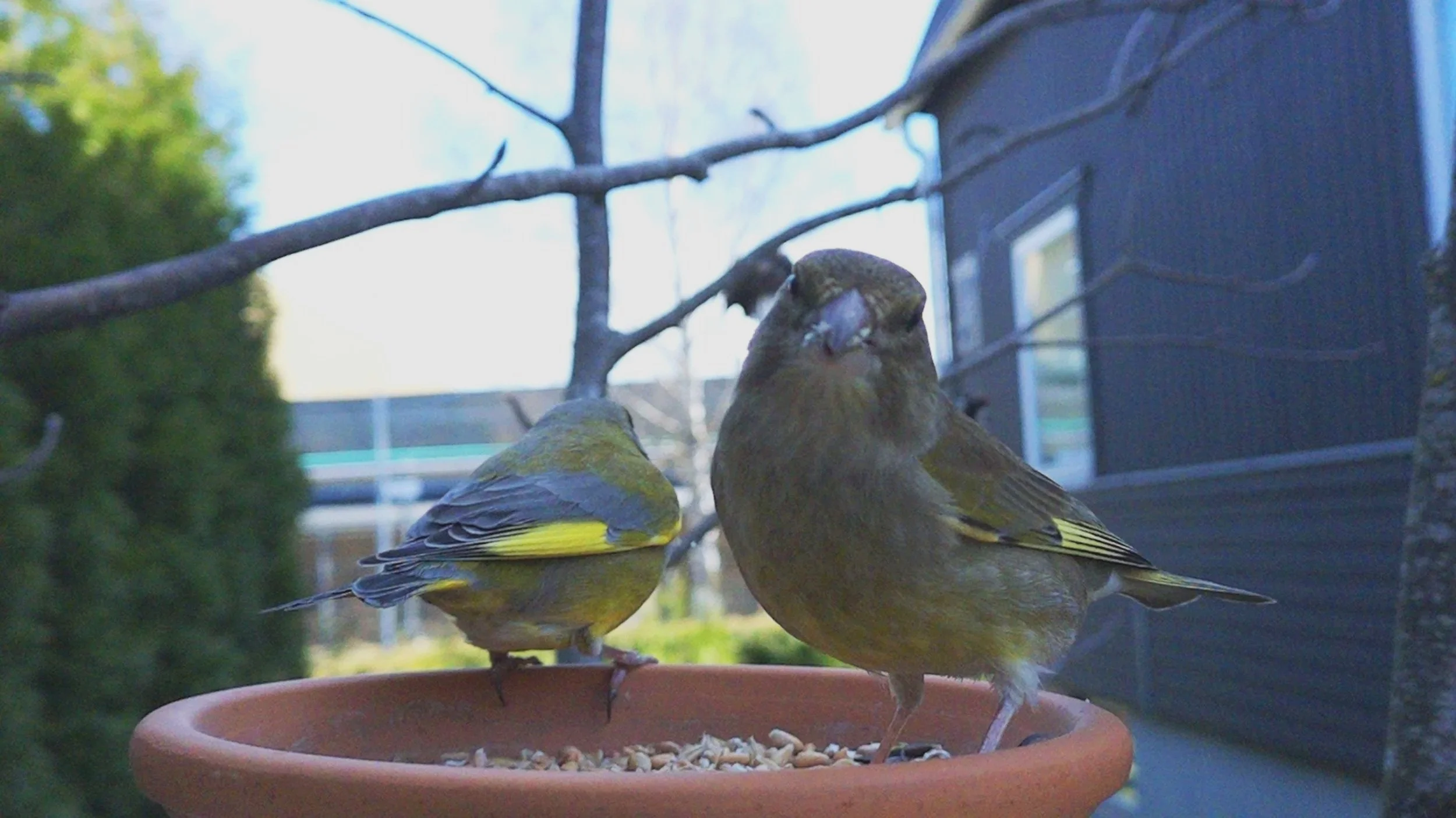
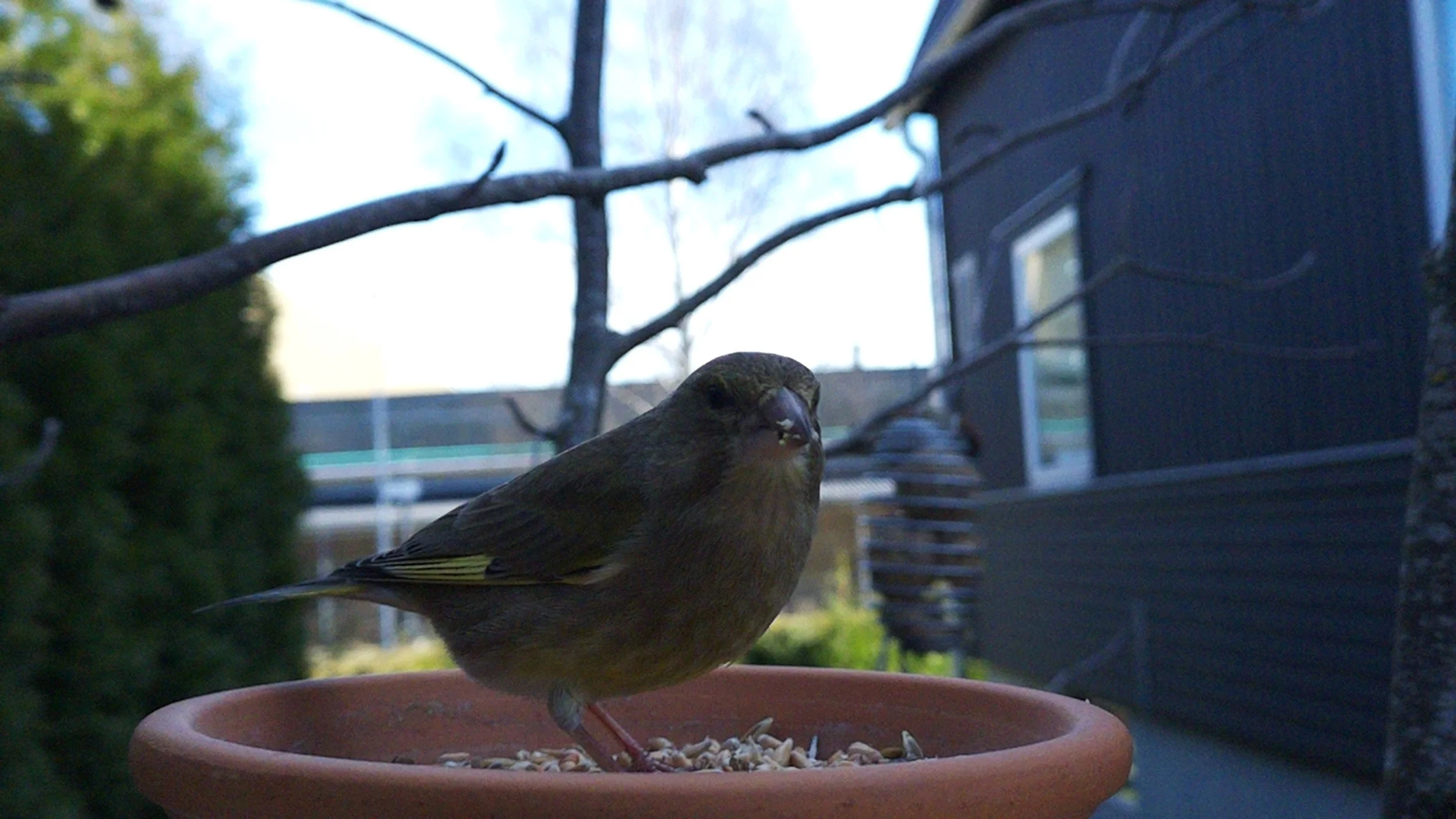
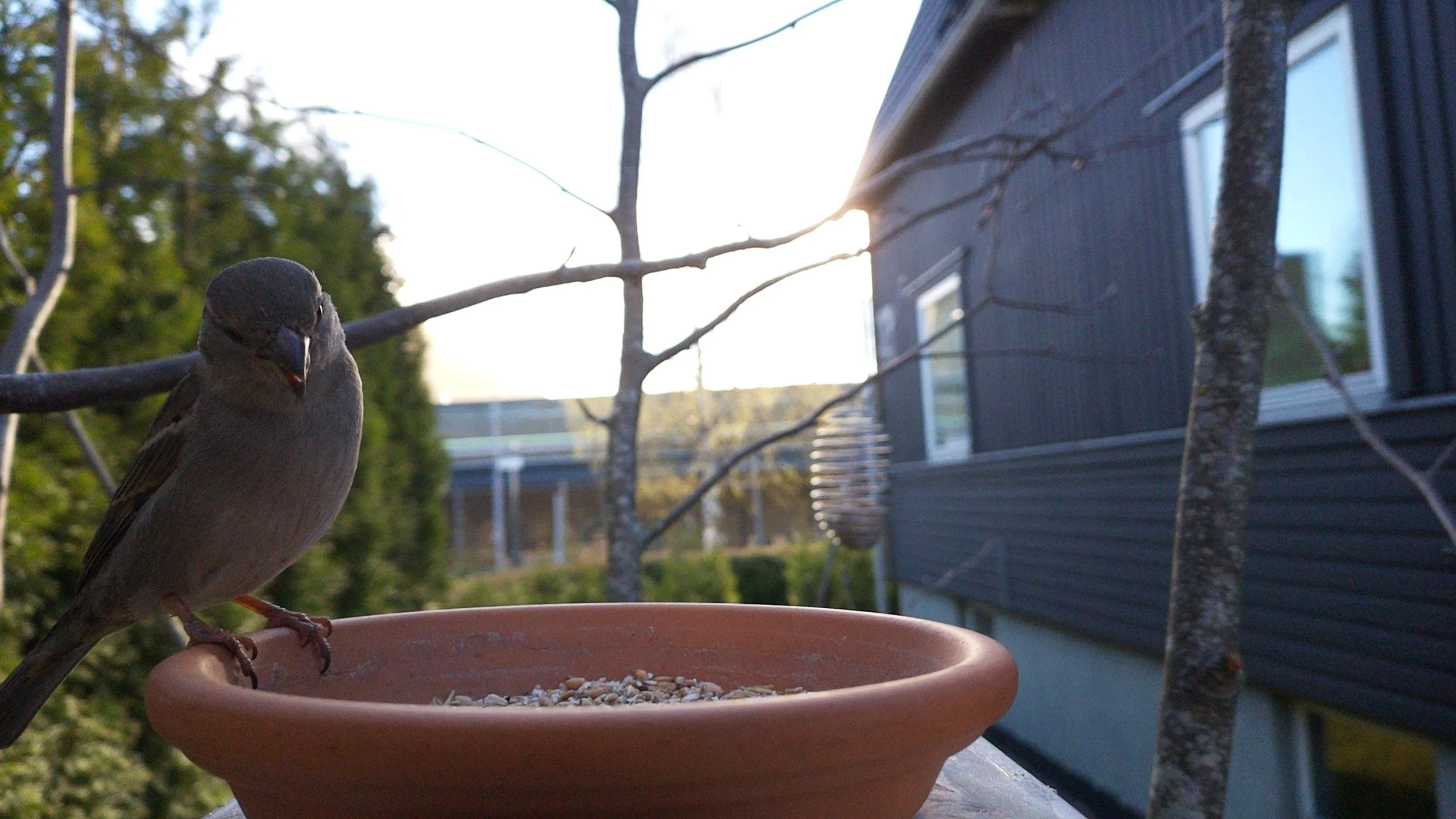
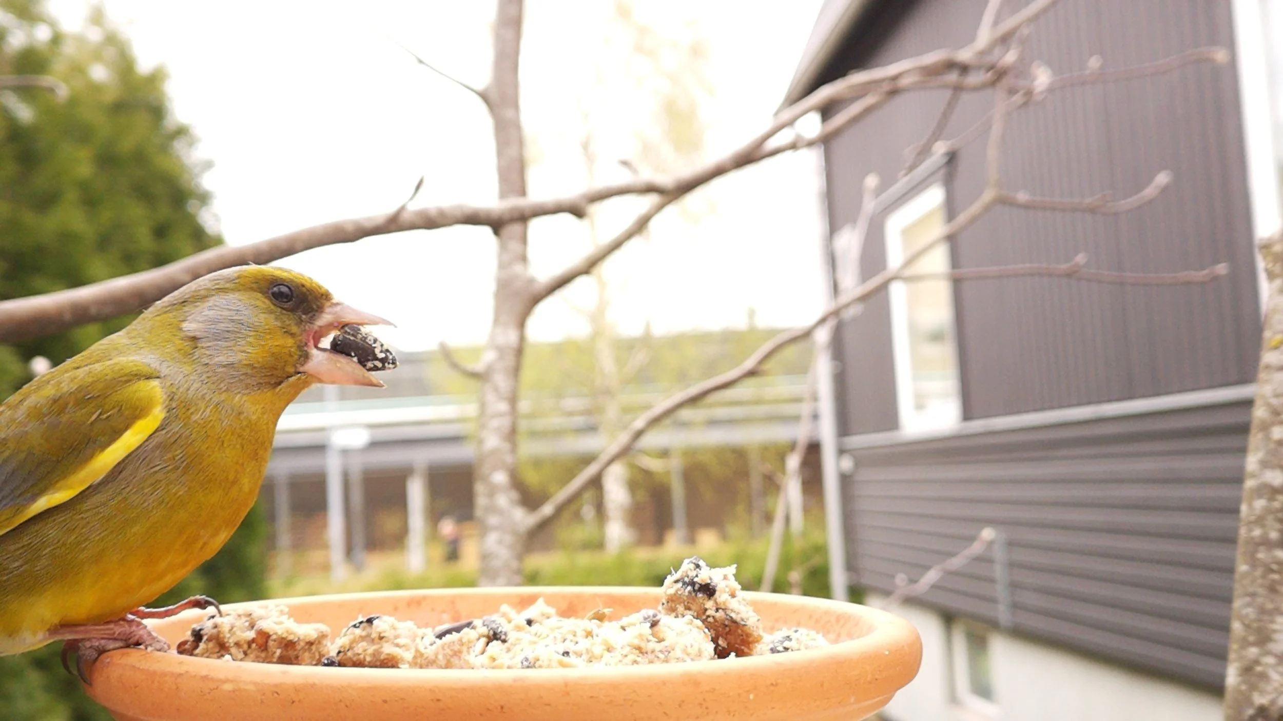
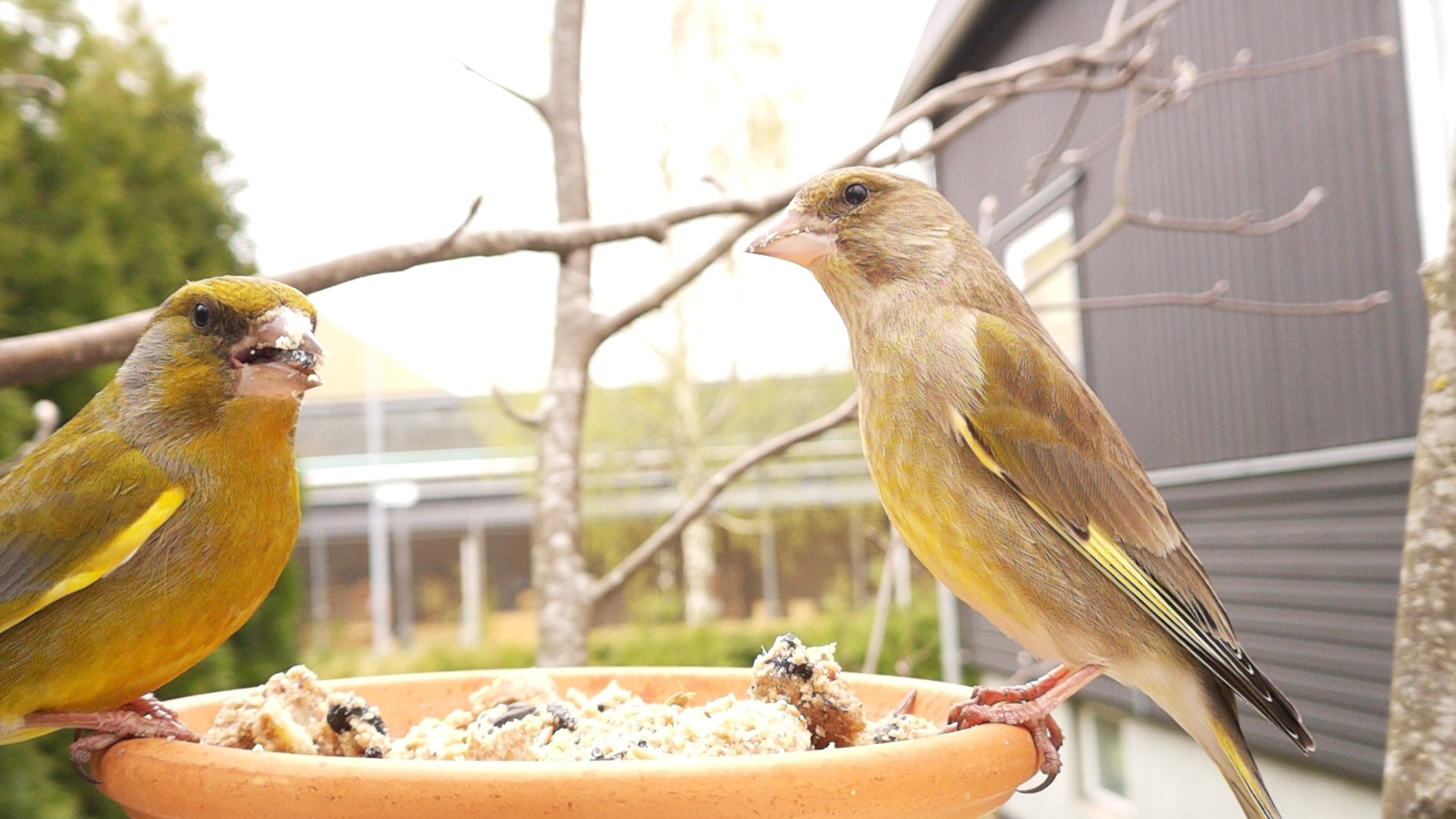
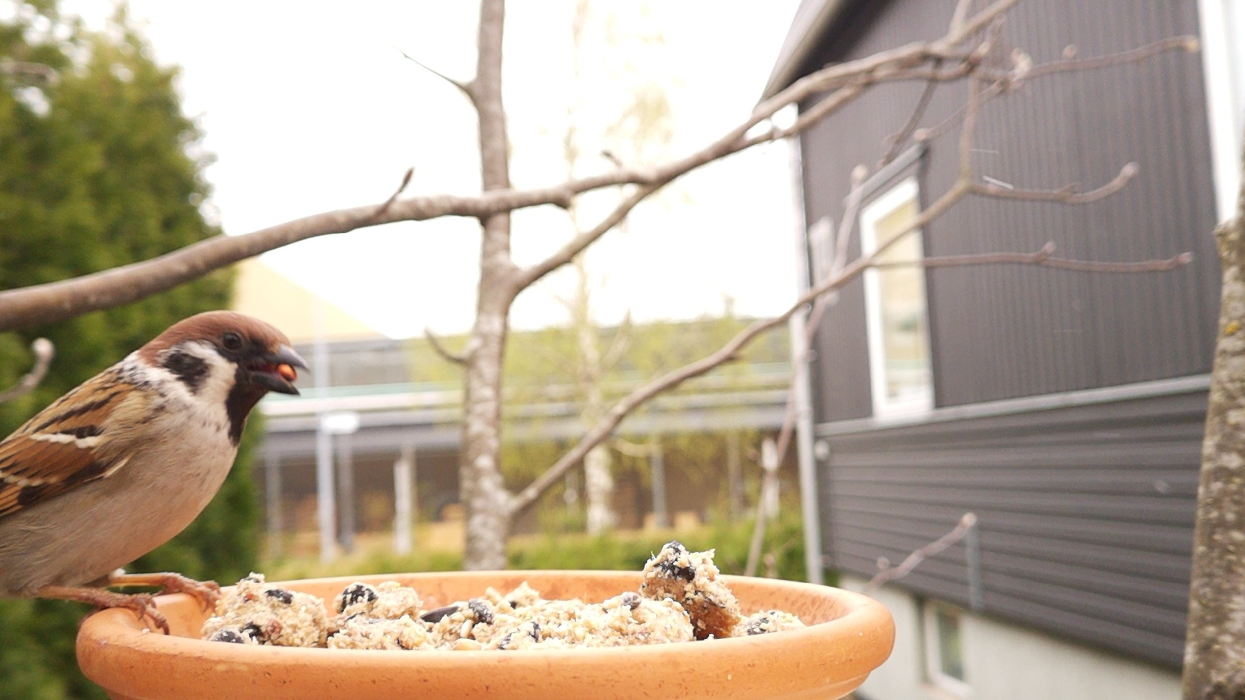
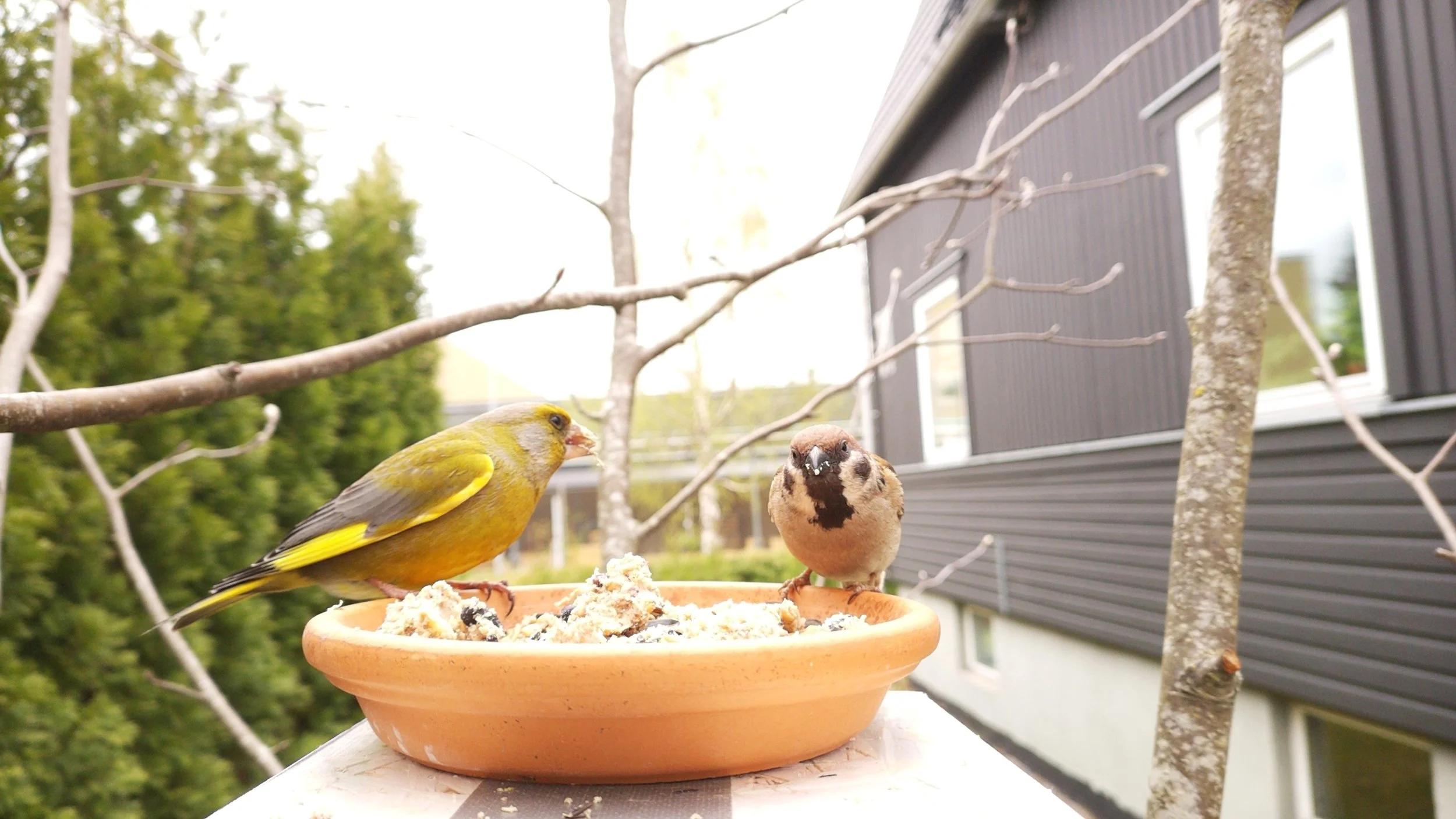
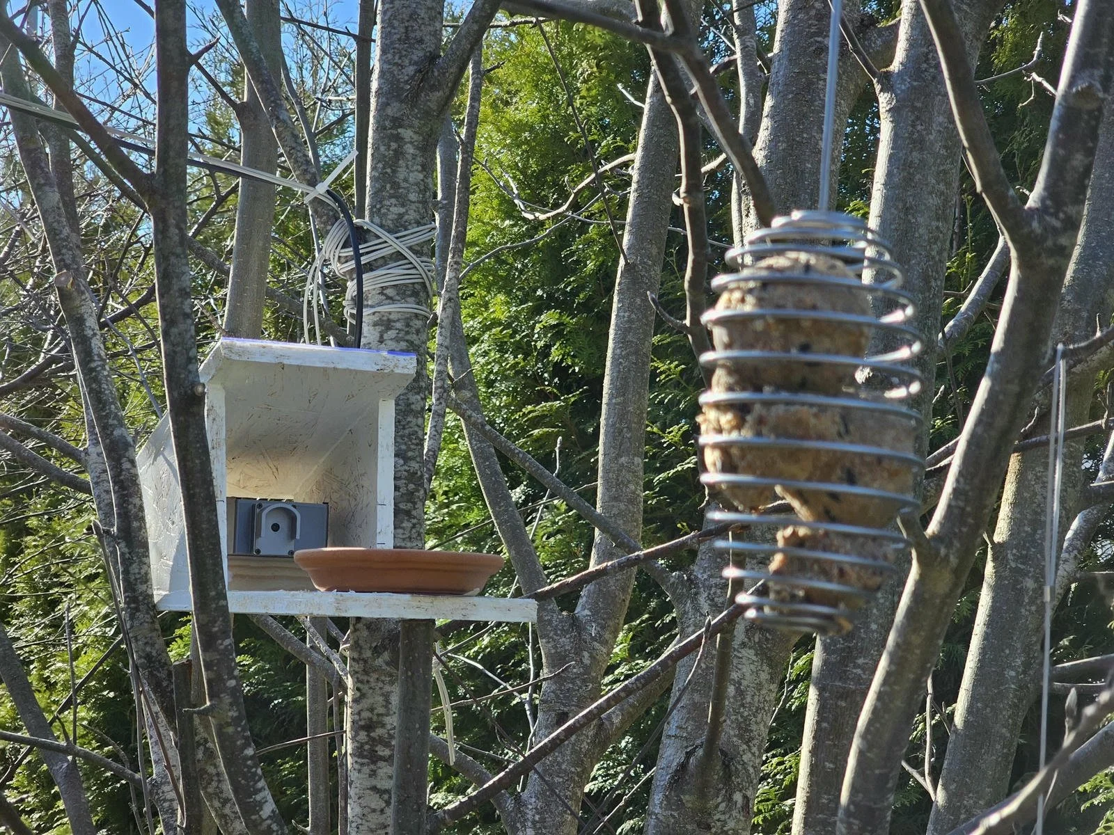
The camera in its shed, pointing at the ceramic plate and the feeder. Both feeders are in the FOV of the camera.
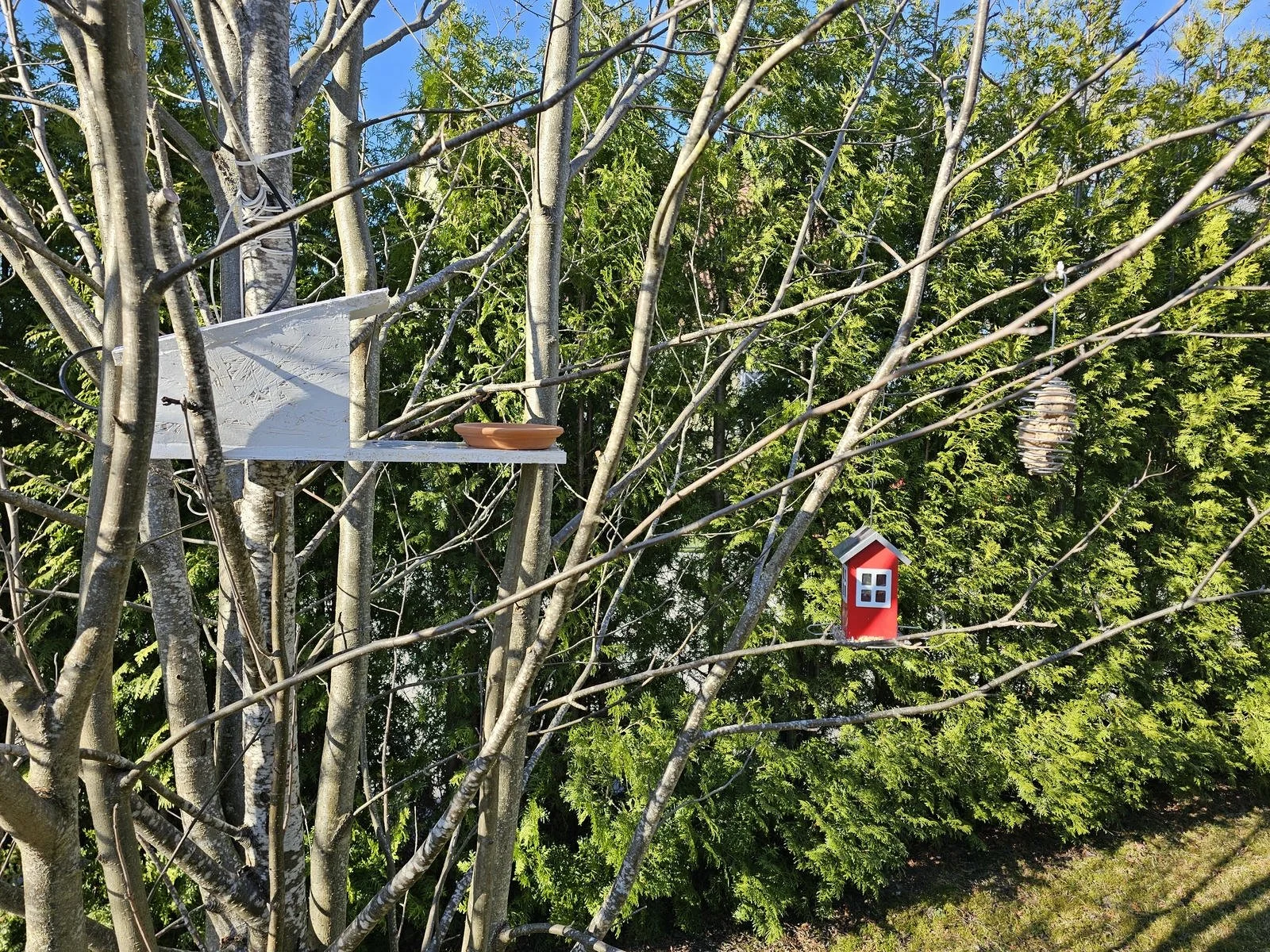
Side view of the camera and feeder arrangement.
The software
Let’s talk about the camera software a bit more. The CamUI software and its documentation are available on GitHub, so I am not going to repeat those details here again. I will talk more about the features and their use.
The software can be reached by the IP address of the Pi. If you can, assign a permanent IP address to your Pi in your router, so you can bookmark the address and reach the camera easily from the browser. The landing page shows the connected camera module and two modes: camera and timelapse. The timelapse mode is under development, so it is not available.
Opening the camera brings us to the live feed and the control panel. The camera can be viewed in desktop and mobile modes. The controls and the feed are the same; it is only the layout of the UI that changes between these two modes. The first and most important feature is the capture image button. Pressing it grabs the actual frame. The process takes some time, but this is probably due to the fact that I am running the software on the weakest possible Pi. The feed is quite good; most of the time it is smooth and nice, however, sometimes I can see glitches. I still don’t know if it is due to the WiFi connection or it is a hardware issue, but I accept this quality for now.
The first control that we can change is the orientation of the feed. This option can be used to flip the image both along the vertical and the horizontal axes. It is useful, for example, when the camera is placed upside-down.
The next option is the autofocus settings. This allows a lot of adjustments. We can switch between manual and auto mode. In manual mode, there is a slider that allows us to change the focus settings. We can even choose the range of the focus for the autofocus mode. This allows the camera to prefer close-up objects (macro mode) or objects at normal distances.
Then, we can adjust the gain and exposure settings. I haven’t figured out this one yet. The exposure time has a ridiculous slider that can be adjusted between 26 and 220416802 (200M). So, even if I just gently move the slider, I set the value too high, and the image will turn white due to the too-high exposure time value. Luckily, I can move the slider with the arrow keys, but it is still cumbersome to adjust it. It does not make sense. The analogue gain is a bit better to adjust, but as expected, increasing the gain introduces noise. I guess this is the equivalent of setting the ISO value. A good way to set the exposure to a more or less reliable value is to toggle the “AEC-AGC Locked/AEC-AGC Enabled” button. This allows the camera to recalculate the exposure parameters. There are a few extra exposure-related adjustments, but I only found the metering mode to be useful.
The white balance adjustment can be enabled or disabled, and it can be set to auto mode, or we can choose a preset value. But in the next mode, under the brightness and contrast adjustments, apart from adjusting the brightness and contrast, we can also directly adjust the colour temperature of the image. So, there is no need to fiddle with the white balance modes.
Then, we can change the still image resolution. These are the available options for the snapshots we can take when pressing the capture image button. As an extra, the software can even save the image as a RAW image (DNG). We can also select a few sensor modes. These modes control the live feed and its resolution. The first mode, “Mode 0”, is the fastest. But this comes at a cost, because to allow a higher throughput, the software crops the original image of the sensor, and it transmits a smaller image with a smaller field of view. The next mode, “Mode 1”, provides a larger field of view, but the live stream becomes more laggy and more unstable, probably due to the much larger amount of data that must be transmitted. Finally, the “Mode 2” is supposed to be the full resolution feed. However, I was not able to use this mode; I just got a blank image. I don’t know if this is a software or a hardware (Pi or camera?) limitation. Finally, the camera settings can be saved as profiles, and we can recall them when needed.
Within the UI, there is an option to check the captured pictures under the Image Gallery page. We get a gallery of thumbnails, and we can use the built-in viewer to open the images in place, or we can download them. The images can be deleted as well, so they don’t use disk space.
Then, under the camera info page, we can check a few pieces of information about the camera. We can even fetch links that can be inserted into, for example, VLC Player or OBS, so we can watch or even stream the feed of the camera.
Under the About section, we can read all the important information about the software.
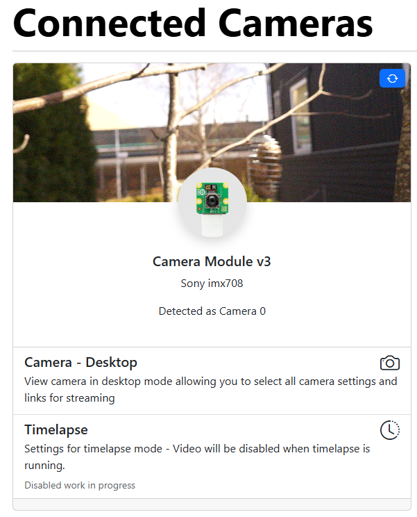
CamUI app’s landing page
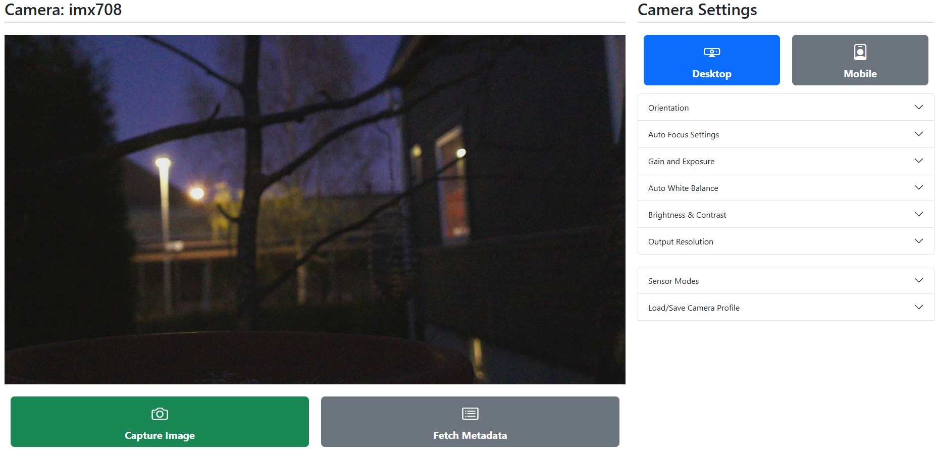
CamUI app’s camera page in desktop mode.
Software tweaks
Finally, let’s talk about a few tweaks I applied to make the camera a bit more usable.
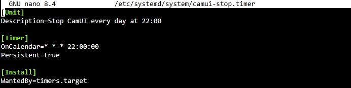
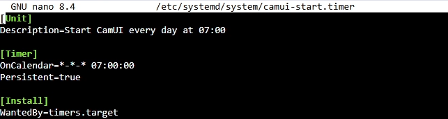
Since the camera won’t be used all day long for practical reasons (daytime, working hours, etc.), I set up an automated script that starts and stops the camera service at predefined times. So, every morning at 7:00, the camera service starts automatically, and at 22:00, the camera service stops automatically. So when there is no sun, the camera is not streaming. Both birds and I are sleeping during the night anyway. This saves some battery in the long run.
Additional content
Get relevant parts using my affiliate links!
Get the 3D files from my PCBWay project page

If you found this content useful, please consider joining my YouTube channel’s membership or leaving a donation.
Also, please consider using my affiliate links when buying relevant gadgets.