Building a 20x20 cm desktop cloud chamber - Part 1
In one of my previous projects, I built a tiny 4x4 cm cloud chamber. It was relatively simple to build it and it was working well, however, due to the small surface area (16 cm2), it was not super spectacular. In this project I am attempting to build a much larger, 20x20 cm cloud chamber which is hopefully more spectacular than the 4x4 cm one.
Furthermore, I tried to carefully document each steps and considerations in this article and video. I tried to select the parts and methods in a way so most of the components are off-the-shelf, so people who want to replicate the device can do it with a minimal effort.
A little background on cloud chambers
Probably the best idea for you is to visit the Wikipedia page of cloud chambers and read it, but I summarize it here, just to have everything in one place.
The cloud chamber is simply just a box that contains supersaturated vapour, typically of some alcohol or water. When a charged particle passes through this supersaturated vapour, the vapour along the path of the particle condenses. As the vapour becomes small droplets, the trajectory of the particle becomes visible for a short amount of time.
If we follow this trajectory long enough, we can identify nuclear reactions, for example, the annihilation of particles. Since charged particles interact with magnetic fields, their trajectory can be deflected with a strong magnetic field which also helps their identification. For example, their charge (electron vs. positron) can be identified. Or, if we know the particle (electron) and the properties of the magnetic field, we can calculate the particle’s velocity from the curvature of the tracks.
Typically, two types of cloud chambers are used: expansion type and diffusion type. The expansion type of cloud chamber utilizes the adiabatic expansion of the air inside the chamber. When the humid water inside the expansion cloud chamber is expanded, it makes the air cooler and the water in the air to condense water vapour. Later, this vapour is used to detect the particles. The diffusion type of chamber consists of a cold bottom plate. When the alcohol evaporates at the top of the chamber, the vapour descends to the bottom, towards the cold plate. When it reaches the cold plate, it condenses. Due to the temperature gradient between the cold plate and the top of the chamber, there is a layer of supersaturated vapour forming at the bottom of the chamber over the cold plate. This layer of vapour is used to detect the particles.
In this article, I implement the diffusion type cloud chamber using Peltier coolers.
Technical challenges
So, as I wrote in the previous section, we need to produce very low temperatures (-20°C to -30°C) in order to create the supersaturated alcohol vapour layer where the ionizing particles can create visible trails.
Many tutorials on the internet show how to make a simple cloud chamber using dry ice or even liquid nitrogen to create a cold enough surface. Yes, they make the cooling part simple, but sourcing these things is not super simple, and they can also be dangerous to work with. Actually, working with these substances requires a lot of safety considerations when the work is done at a “professional place” (e.g. at a research facility).
I wanted to build something more reproducible, something that is relatively cheap, easy to build and could run 24/7 if required. Since the first tiny Peltier cooler-based cloud chamber I made was a success, I decided to stay with Peltier coolers. They are not super efficient, but when they are dialled in correctly, they can produce a large temperature gradient between their hot side and cold side.
I remembered that while I was browsing the internet, I saw a module that has a roughly 20x20 cm surface area and is cooled by Peltier coolers. It is a cold plate with four Peltier coolers sandwiched between a 4 mm thick aluminium plate (cold side) and two large heatsinks with four 8 cm fans (hot side). So, as a first step, I bought one of these devices and tested them. Based on the heatsink that is supposed to cool the hot side of the Peltier coolers in the device, I already suspected that I might not be able to reach below -20°C. Nevertheless, I tested it to see how much I can squeeze out of the device. With the original fans and supply current around 4 A per Peltier cooler, I could reach roughly 2°C on the exposed cold surface. This is still 20°C away from my minimum target temperature (-20°C). Then I disassembled the device, replaced the thermal grease and tested the cooler again, but this time with a much more powerful fan, but I could barely reach 0°C on the cold side. It was very obvious that the heatsinks are not sufficient, they cannot remove the heat from the hot sides well enough.

6-heatsink CPU coolers. Ideal for high-performance Peltier coolers.
So, the next step is to think about an alternative way of cooling the hot side of the Peltier coolers. I have great experience in this topic. I can either go with water cooling or with air cooling using a better heatsink, preferably with heat pipes. Water cooling would be a bit too tedious because of the 4 Peltier coolers. It would involve a lot of plumbing and some expensive parts. On the other hand, Peltier coolers also can be cooled very well using CPU coolers with heat pipes. A great advantage is that they can easily remove 120-150 W heat quickly, it is easy to install them, and they are cheaper than water cooling. So, it is the perfect match for this application.
After deciding to go with the CPU coolers, I ordered four coolers of the same kind that I already have at home and tested them thoroughly in the past few years. Then, I removed the heat sinks and the Peltier coolers from the original plate. I cleaned up everything, installed a few NTC thermistors at the back side of the cold plate and fixed the insulation.
My next problem is that the original cold plate is not exactly 20x20 cm. It is 18x21 cm. So, I printed an adapter frame to make it 20x20 cm. Why 20x20 cm? Can’t I just build any shape and size using acrylic sheets? Yeeessnooo… and this is actually a material selection problem! The chamber needs to contain isopropyl alcohol (IPA) vapour. Unfortunately, acrylic (PMMA) and polycarbonate (PC) sheets cannot really tolerate IPA, it dissolves them. Since the walls of the chamber would be exposed to alcohol vapour for a prolonged period of time, I could not afford to rebuild the chamber every X time. Instead, I picked a better material. Polyethylene terephthalate glycol, a.k.a, PETG. This is a durable polymer and it can withstand solvents better than PMMA or PC. I looked around at the local hardware store and I found a nice 20x20 cm transparent plastic container made of PETG. So, that’s why I go for 20x20 cm. Probably PET, PP or PE would be even better, but I could not find off-the-shelf products made of them, and sourcing sheets seemed a bit challenging.

CPU cooler fixed on the aluminium plate. Notice the felt pad between the mending plate and the CPU cooler, as well as the nylon washers!
The next step is to figure out how to mount these behemoth coolers. The aluminium plate already has two M4 threaded holes for clamping the heatsink on each Peltier cooler. I did not want to mess around too much and potentially mess up the aluminium sheet, so I decided to use these holes. I looked around on the internet and found some nice mending plates for this purpose. They are strong enough to not bend when the cooler is clamped on the aluminium sheet and the hole across the centre of the plate allows us to adjust the screws according to the distance between the holes on the plate. Also, as an extra effort to avoid transferring heat through the mounting bolts, I did two things. First, I added a felt pad between the mending plate and the back of the CPU cooler. Second, I added nylon washers between the bolt that goes into the cold plate and the mending plate that touches the back of the CPU cooler (roughly 35-40°C while the Peltier is running).
To further improve the lowest achievable temperature, I used some of the freshly discovered high-performance Peltier coolers, the TEC2-19006. I found them a few months ago and tested them to see how cold they can become. They can reach around -35°C without any thermal load, so with a well-insulated cold plate, they should be fine for the task.
Solution
Now all components are ready!
The new Peltiers are placed on the original aluminium sheet
The CPU coolers are mounted on the aluminium sheet
NTC thermistors are strategically placed across several points
Connectors are prepared for accepting power
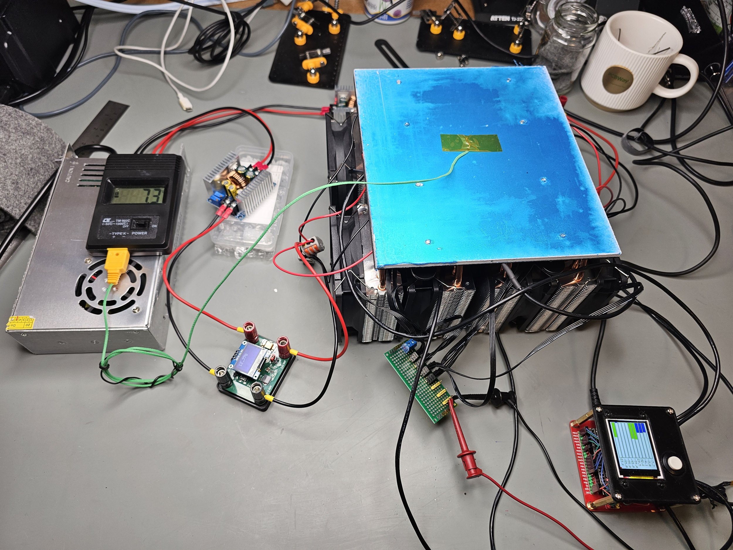
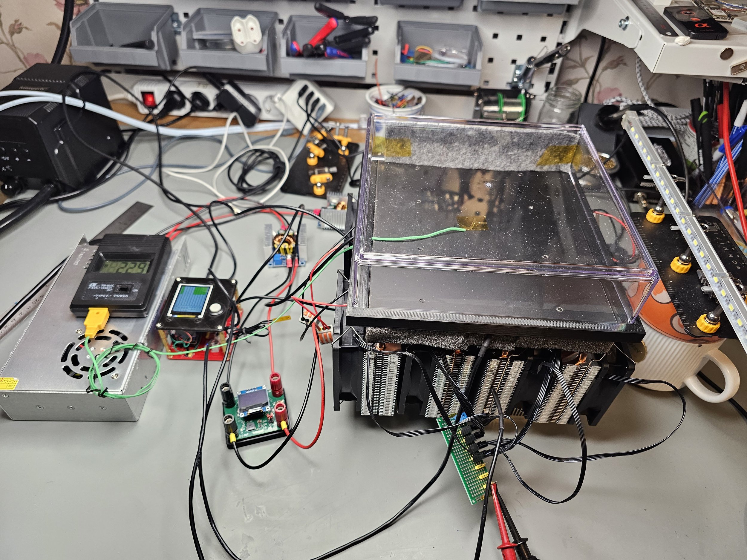
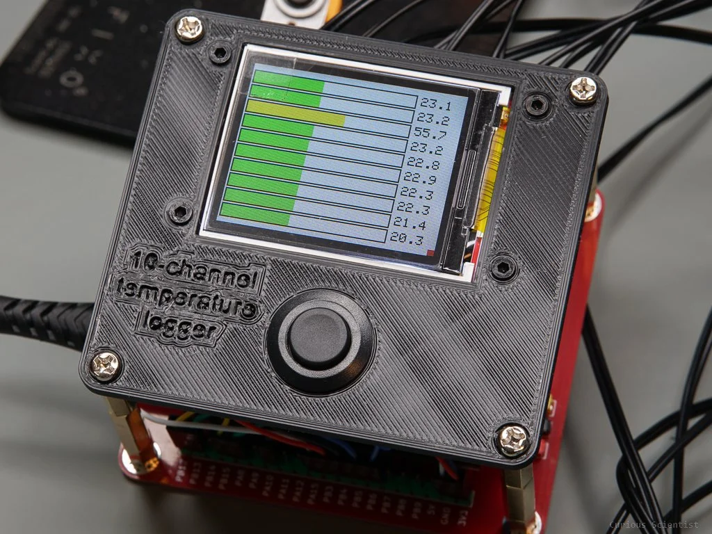
So, structurally, the cold plate part is done. Now, I could just power up the whole thing and see what happens. But first, let’s see what we can do with those preinstalled NTC thermistors. Recently, I made a 10-channel temperature logger. This logger is specifically made for NTC thermistors. So, I will use one of my modules specifically for this cloud chamber to continuously monitor the temperatures.
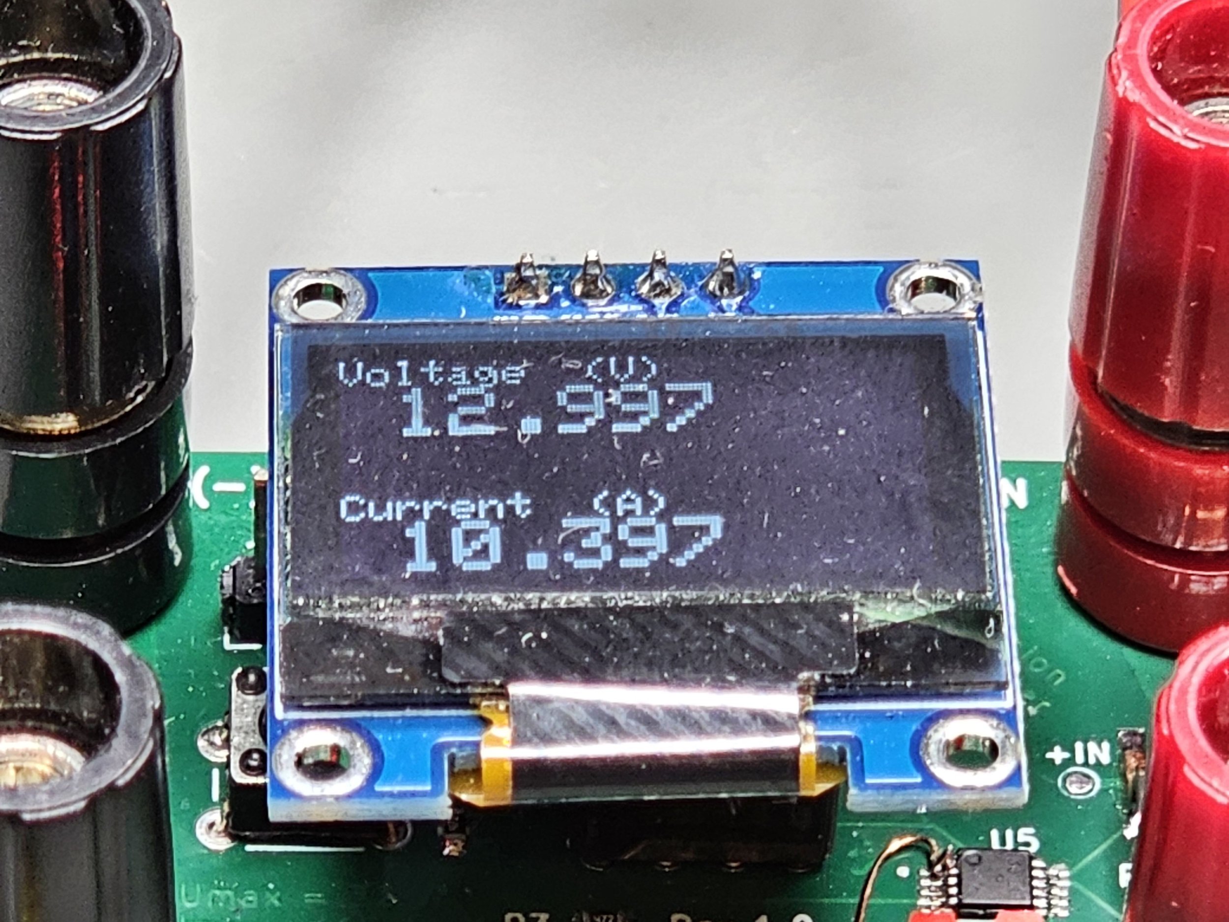
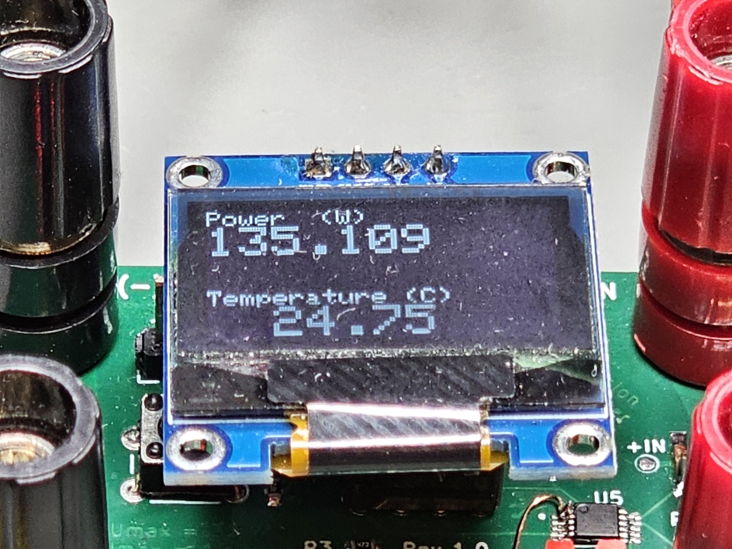
Another recently made project is my 15 A DC power meter. I use two of these, one in each rail at the output of the SZBK07 DC-DC converter. This is very helpful because I can directly see the voltage and current going to the Peltier coolers and then I can adjust the parameters if necessary.
After fixing the measuring instruments, let’s focus on the power supply. Since these Peltier coolers have very similar characteristics to the original Peltier coolers in the cooling plate, I use the same power supply configuration that I used to test the cooling plate. So, the mains power is converted into 24 V DC voltage and the power supply can supply a maximum of 16.7 A. This is 400 W of electrical power. This power is split into two rails and each rail is connected to the input of a SZBK07 DC-DC converter. I use this converter to drop the 24 V down to roughly 12-14 V. Assuming an 80% efficiency, we have 320 W power available. This is split into two, so 160 W for each DC-DC converter. At 14 V, this means roughly 11.4 A. Since the Peltier coolers are rated for 6 A and their sweet spot is around 5 A, the power will be just enough. The Peltier coolers are connected in pairs, so one rail with a DC-DC converter feeds 2 Peltier coolers.

Powering schematics. In this project, I replaced the TEC1-12705 units with TEC2-19006! I just reused the image.
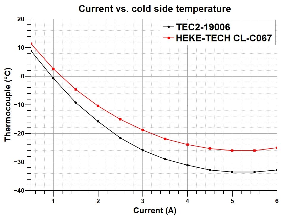
Cold side temperature vs. current consumption. The mentioned “sweet spot” is around 5 A.
Now the device is equipped with thermometers and power monitoring devices and the power supply is connected so there’s everything in place to run a test.
The first test is done with an exposed cold plate. I simply started the cooling fans on the CPU coolers, then I started the DC-DC converters and adjusted the voltage so each Peltier receives around 5 A. Then I was just waiting until the temperature settled. I could easily reach -9°C and if I wait a bit more and don’t disturb the air in the room, I can probably reach even below -10°C.
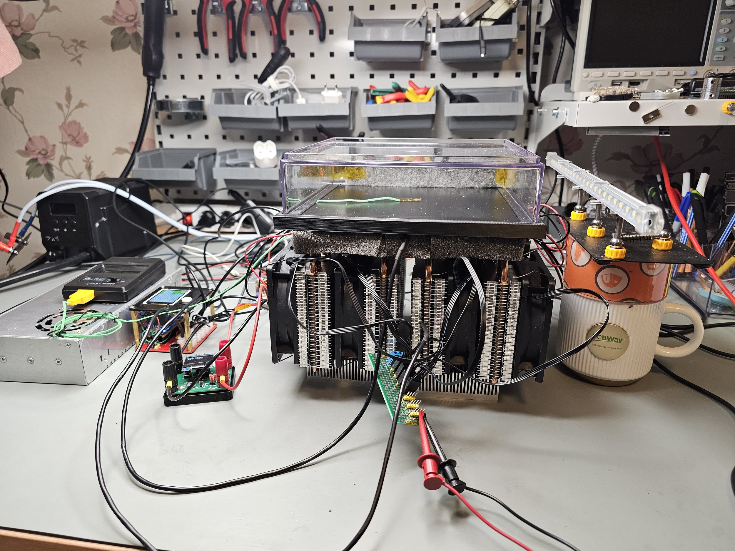
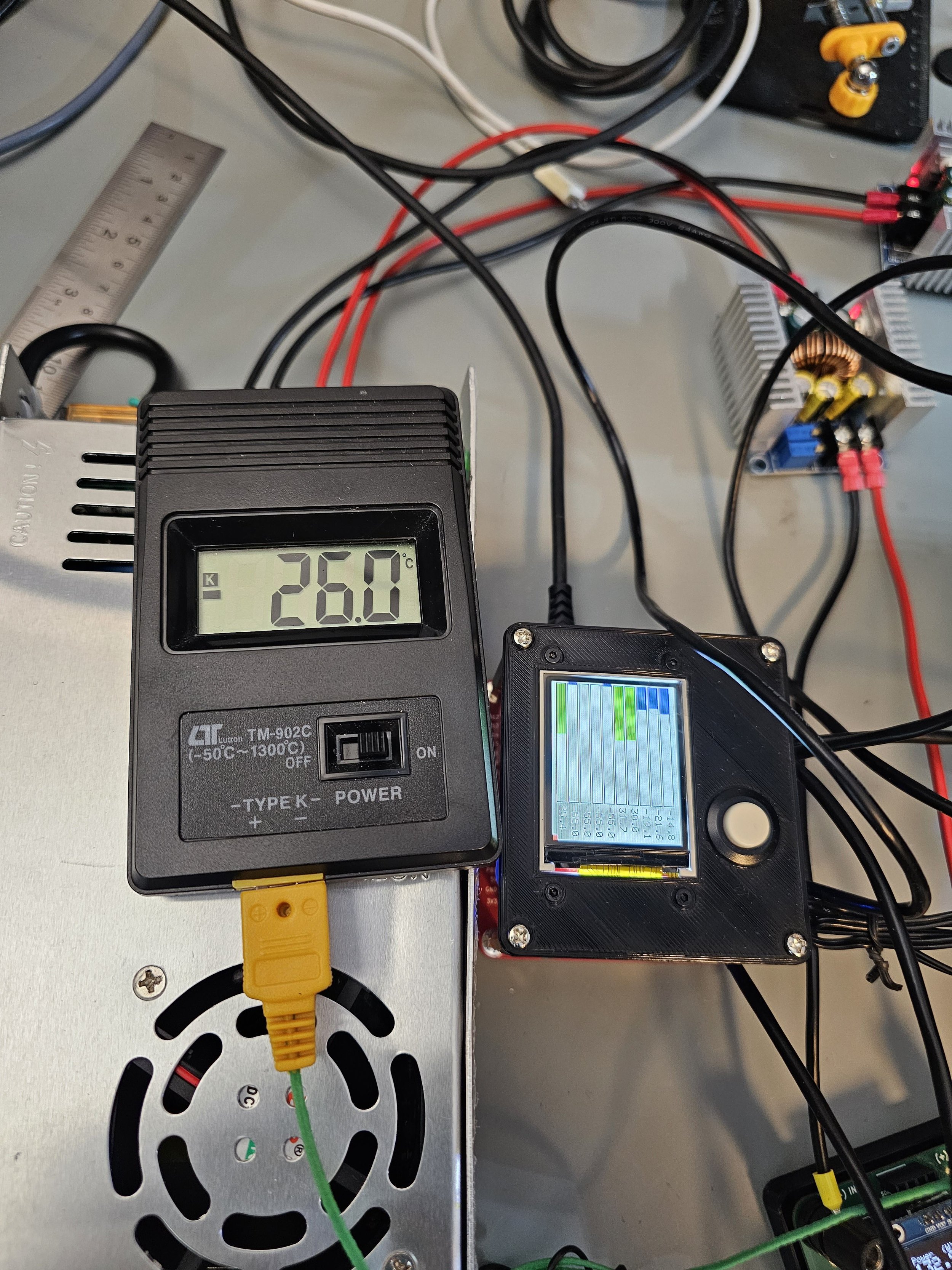
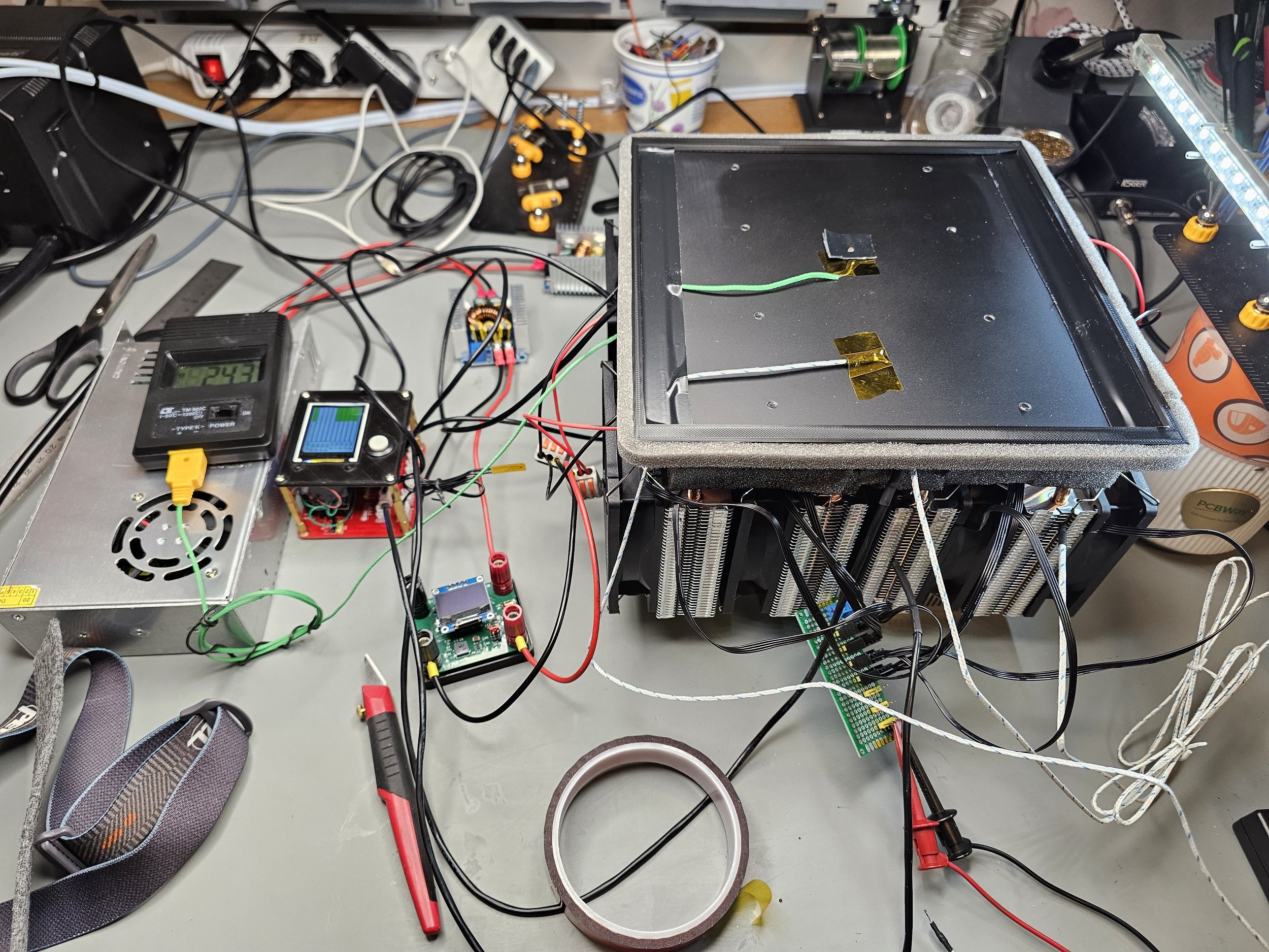
After observing the results with the exposed cold plate, I put the 3D-printed skirt on the aluminium plate and mounted the transparent enclosure. Just to be sure, a K-type thermocouple at the centre of the top side of the cooling plate was monitoring the temperature. Just to see if we get a different temperature reading as compared to the readings of the thermistors.
The first trial was not super successful, the temperature started to max out at around -19°C. This was definitely not enough. I decided to abort the whole experiment and fix a few things on the cold plate. I added more insulation to the bottom side over the already existing insulating foam. I also added some foam to the skirt to prevent even more heat leakage. I also painted the cold plate back with some acrylic spray paint to give a better contrast to the vapour streaks. After reassembling and restarting the system, I could reach -26°C relatively easily, and if I waited a bit more I could reach below -28°C.
However, I discovered further crucial issues that were not so obvious. First of all, the felt pieces really have to be soaked with IPA. It is not enough to just dampen them. Also, while speaking about the felt piece I want to suggest a really smart way of mounting them in the chamber: magnets. I used some strong neodymium magnets on both sides of the chamber to fix the felt against the chamber walls. Since most of the glues get dissolved by IPA (or at least, they get weak), this “mechanical contactless” mounting is a good way in my opinion. In addition to the soaked felt pieces, I added a small container of IPA to the chamber as well. The reason why I suspect that the IPA was not enough is that when I started the experiment, I could see the vapour cloud very early, however by the time the cold plate reached the target temperature, the vapour simply disappeared.
Another issue I discovered and did not think about is the light source and the 3D-printed skirt. The skirt sticks out by 1 mm from the plane of the cold plate. Therefore I cannot shine the light fully parallel to the surface of the cold plate. I noticed that if the light is not parallel, the streaks do not show up really well. So, I think that the next version will have a slimmer skirt without the sticking-out part.
Another probable issue is probably somewhat related to the first issue with the alcohol vapour. After a while, I noticed that the top of the chamber is getting foggy. That means that the temperature of the enclosure dropped below the dew point of my room’s air. I could easily get rid of the fog by blowing warm air on it, however, this is not ideal. If the top of the chamber was able to cool down to such a low temperature, it suggests that the chamber’s height is too low. It also suggests that the necessary temperature gradient in the chamber is probably too little. This could disturb or hinder the formation of the supersaturated alcohol vapour layer.
What’s next?
Improving the lights, removing the skirt so the light can go parallel with the surface of the cold plate
Create a higher enclosure to allow a larger temperature gradient in the enclosure and to have the felt pads farther from the cold plate
Sealing the enclosure better in order to hinder the vapour from escaping and in order to hinder any leakage
Fixing the cable management to make the device more presentable
Recording high-definition footage of the cloud chamber in action
Finding a better way to make the cold plate black (IPA attacks the paints) - Yes I know, anodized plates, but they are super expensive.
Bill of materials
Please consider using my affiliate links to purchase the relevant products!
TEC2-19006 Cascade Peltier cooler
Peltier cooler insulation foam
400 W, 24 V, 16.7 A DC power supply
12 V, 6 W submersible water pump
Self-adhesive insulating foam strips
Join my YouTube membership!
Get my power meter and thermistor temperature logger from PCBWay! Click on the pictures!
10-channel NTC thermistor temperature logger with SD card

15 A, 85 V DC Power meter