Testing a 240 W Peltier cooler cooling plate
In this video, I show you this 240 W Peltier cooler cooling plate. I will need this device for an upcoming project, but before I use it in that project I thought it is a good idea to explore and study it and share some information about it.
More details
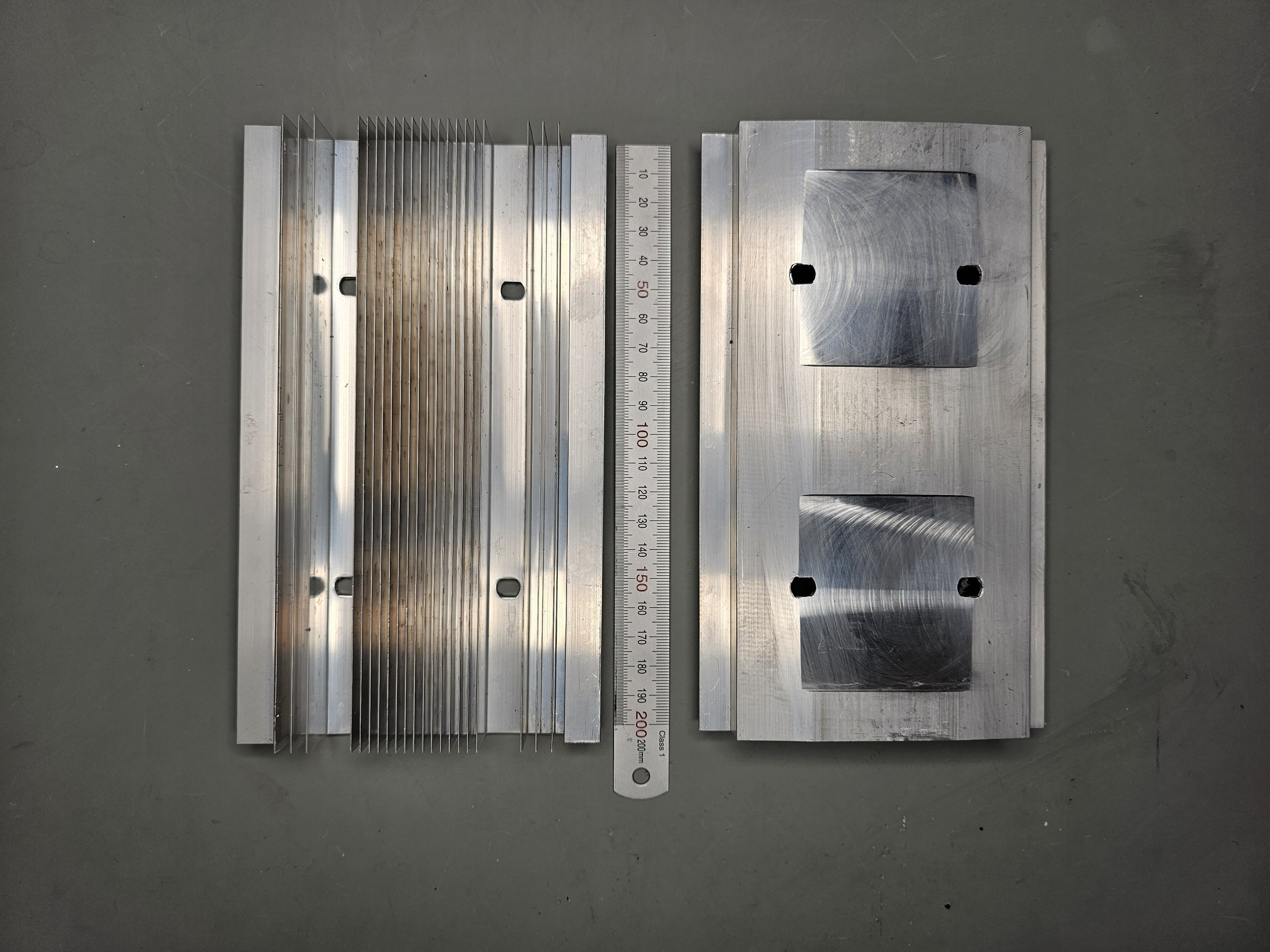
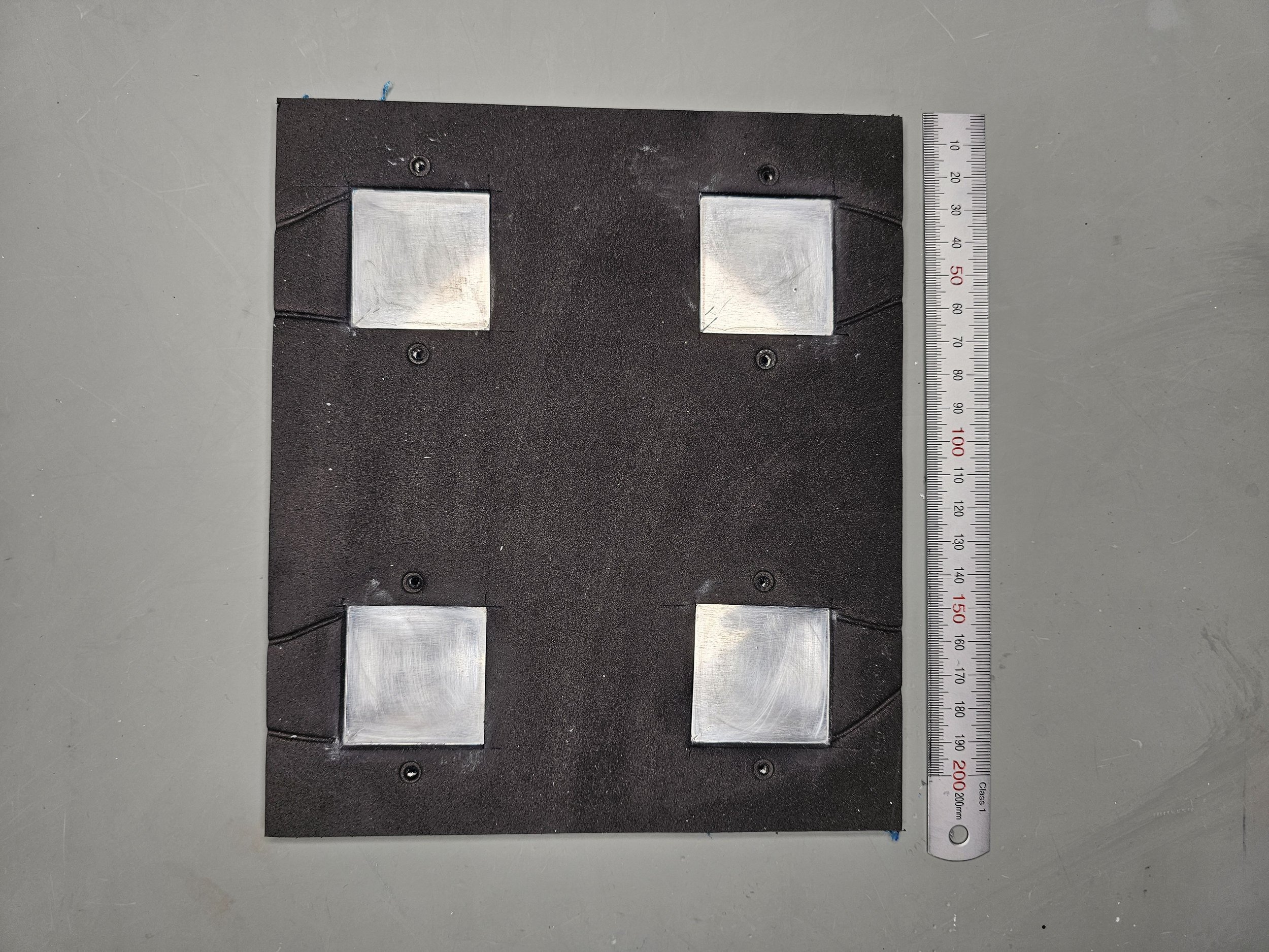
This device is sold as a preassembled kit. It contains a roughly 20x20 cm large, 4 mm thick aluminium plate, 4 TEC1-12705 Peltier coolers, 2 heatsinks and four 8 cm fans (12 V, 0.2 A each). The cold sides of the Peltier coolers are attached to the 20x20 cm aluminium plate, and the hot sides are attached to the heatsinks. The back side of the aluminium plate is covered by a 2 mm thick insulating foam to separate the cold aluminium plate from the warm heatsinks.
Since the device is powered with TEC1-12705 Peltier coolers, it is easy to know the characteristics of the system, we just have to rely on the datasheet. But I already struggled in the beginning. They claim that the performance of the cold plate is 240 W, and one would assume that this value is the cooling power, however, it would be impossible. Even at the highest Qc value, these Peltier coolers only produce 49 W of cooling power (Qc). 49 W x 4 is only 196 W. Nearly 50 W less than the promised wattage. Furthermore, this is very misleading information, because this Peltier cooler can only provide this cooling power (49 W) when the dT (the temperature difference between the cold side and the hot side) is nearly zero. So, “at 240 W”, the device is pretty much useless because it cannot provide any useable temperature difference.
We should look at the performance chart of the TEC1-12706* to get a more meaningful, and most importantly, achievable cooling power. For example, let’s assume that the hot side will be around 50°C and we want the cold side to be at 0°C. This is dT = 50°C. By looking at the performance chart, we can see that if we run the device at around 5 A, we can achieve 20 W cooling power. So, while maintaining a 50°C temperature difference between the hot side and the cold side of the Peltier cooler we can achieve 20 W cooling power (See Graph 1). This will be 4x 20 W = 80 W. It is a more realistic value.
Furthermore, if we assume an enclosed system where the cold side is insulated, we will actually achieve lower temperatures. As we remove more and more heat from the cold side by cooling down the enclosure, less and less heat to be removed remains in the enclosure. This means that the temperature gradient between the cold side and the hot side can increase. Since we always have some losses, we cannot reach the theoretical maximum values, but we can get close to a 70-80°C difference between the two sides. So, eventually, the cold side (hence, the aluminium plate) will reach something like -20°C to -25°C (See Graph 2).
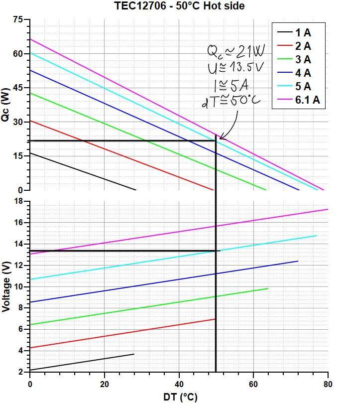
Graph 1
Performance charts assuming a dT = 50°C condition. If the hot side is also 50°C (cold side is 0°C), then the Peltier device is running at roughly 13.5 V and 5 A while transferring roughly 20 W heat from its cold side to the hot side. The total heat on the hot side is therefore 20 W + (13.5 V * 5 A) = 87.5 W.

Graph 2
Performance charts assuming first a dT = 50°C, then a dT = 70°C condition. At condition A, when dT = 50°C, Qc = 21 W. At condition B, when dT = 70°C, Qc = 6 W. This nicely shows the tradeoff between the minimum achievable temperature on the cold side and the cooling capacity of the Peltier cooler.
*I picked TEC1-12706 for this demonstration of reading the graph and explaining the data because I had better datasheets for it. It is also a slightly better Peltier cooler, so if the four TEC1-12706 cannot achieve 240 W, the four TEC1-12705 cannot achieve it either. Furthermore, I first assumed that the device has TEC1-12706 in it (as also seen in the video) because of the advertised 240 W value. The TEC1-12706 can achieve 60 W of cooling power with a dT ~ 4°C.
First impressions
First, I ran the device in the as-received condition. In order to be able to test it to the limits, I had to create a circuit for powering all four Peltiers simultaneously. However, I did not want to go all the way up to 6 A, because from earlier measurements I know that the “sweet spot” of the TEC1-12706 Peltier cooler is around 5 A. Above 5 A, a further increase of the current will eventually lead to higher cold side temperature due to the fact that the Joule heating overpowers the Peltier cooling. I want to reach as cold as possible cold side temperature, so I am chasing the “sweet spot” here.

Simplified schematics of the power supply chain. Each SZBK07 DC-DC converter feeds two Peltier coolers. The coolers are connected in parallel to the DC-DC converters, so they are at the same voltage.
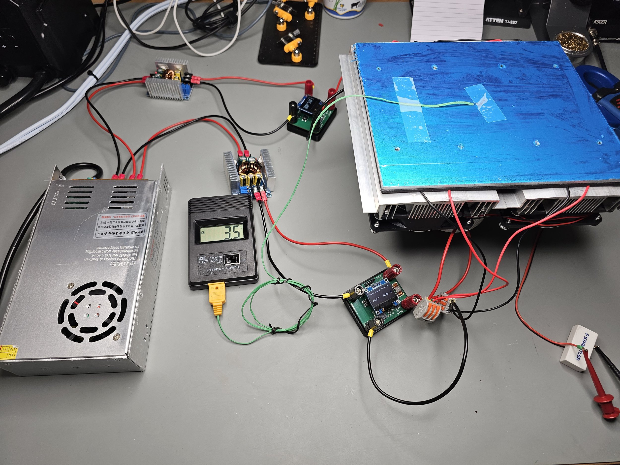
I have a 24 V, 16.7 A DC power supply. This is 400 W of electrical power. I convert this power to lower voltages using a SZBK07 DC-DC converter. Also from my earlier measurements, I know that at 5 A, the Peltier runs at roughly 14 V. This means that each Peltier consumes 70 W. So, 4 Peltiers would need 20 A at 14 V, or 280 W in total. I wanted to run the Peltiers in pairs, so one pair would need 14 V and 10 (5+5) A. Since the DC-DC converter is driven by 24 V, there is enough room to provide 20 A total at 14 V. Assuming that the converter can do at least 80% efficiency, then I can provide 320 W. I only need to have 280 W, so this looks good on paper. Here I assume that within certain limits the DC-DC converter only cares about the wattage fed to it. So if I feed it with let’s say 24 V and 10 A, which is 240 W, I could theoretically drive something with the DC-DC converter at 10 V and 24 A (efficiency is neglected).
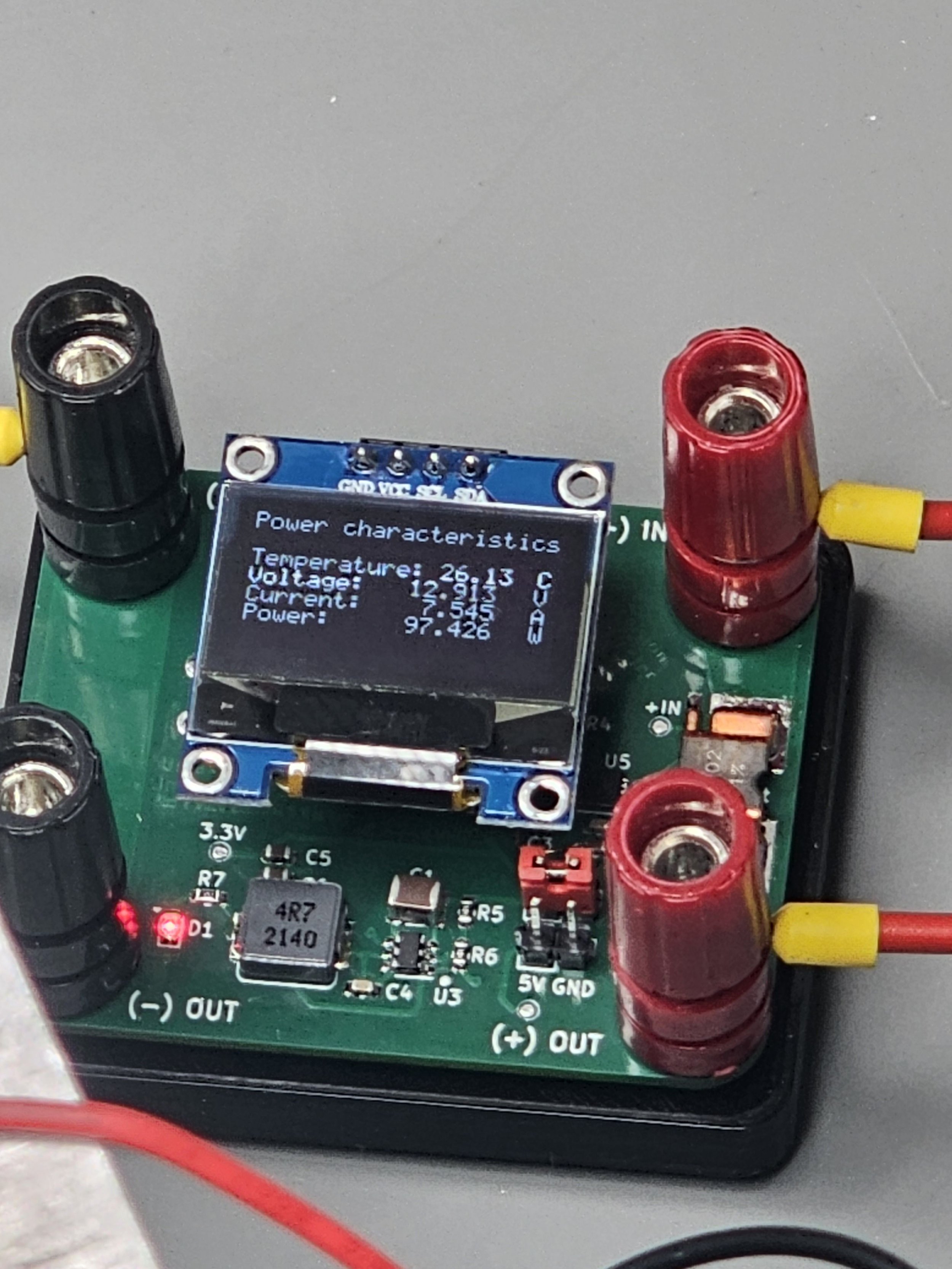
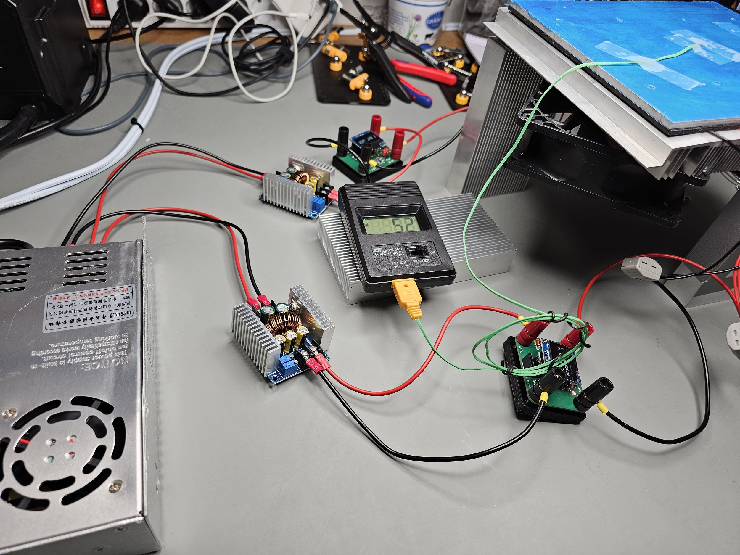
The power is monitored at the output of each SZBK07 DC-DC converter by my custom-built DC power meter.
To get some kind of indication of the performance, I placed a thermocouple right in the geometrical centre of the cooled plate. I also distributed a few thermometers around the hot side heatsink to see how warm the Peltiers go. I let the whole cold side totally exposed for the test, so it can be assumed that in the beginning, there is a considerable heat transfer between the environment and the cold side of the Peltier cooler.
After running the cooler for 10 minutes at ~ 14.5V and ~ 8.4 A (4.2 A/Peltier), the surface temperature only went down to 2°C. Once again, this is with the fully exposed surface, so there’s quite some thermal interaction going on between the cold side and the environment. Nevertheless, this is very disappointing.
The reason for such a bad performance stems from the fact that the heatsinks are really weak. Furthermore, after disassembling the whole device, I realized that the thermal grease was somewhat dry, and the heatsinks were not attached to the Peltier coolers properly. Some of the Peltier coolers had cracks on their ceramic plates which are probably due to the poor alignment (meeting surfaces are not parallel) or too strong clamping. Below you can find a few pictures of the disassembling process with some explanations.
After applying some fresh thermal grease and reassembling the unit, I tested it again. But, instead of mounting back the original fans, I mounted two “Antminer” fans. They are super powerful, they run at 6500 RPM and 12 V and 1.85 A. Even with this cooling, I could barely go below 0°C, and a small disturbance in the room’s air caused the cold side to go up in temperature. So, even with better airflow, the heatsinks are not sufficient.
Additional information and pictures
Use my affiliate links to get the relevant products
Join my YouTube Membership!
Get my DC power meter from PCBWay!