20 A 85 V self-sufficient DC power meter
In this video, I show you my new project. This project realizes a tiny "self-sufficient" power meter that can be inserted into any DC power line thanks to its small footprint. The PCB utilizes the INA238 high-precision power meter chip and the circuit is managed by an ATtiny85 microcontroller.
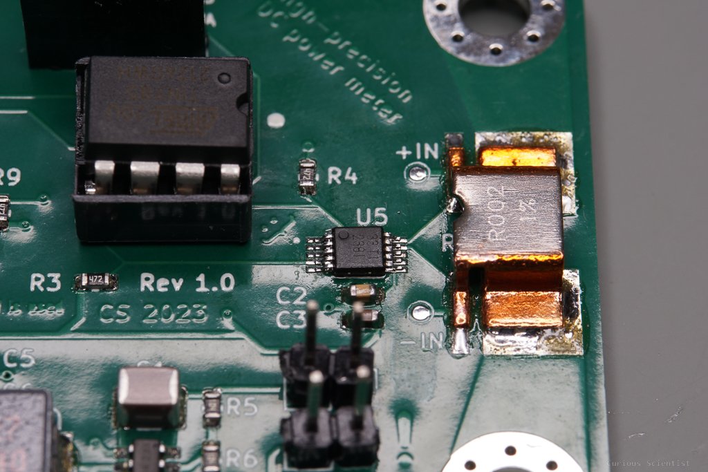
So, as mentioned in the introductory text, the PCB is based on the INA238 power meter. This is a smart little chip which with the help of a shunt resistor can measure DC power characteristics such as bus voltage, current and power. The chip uses the i2c communication protocol, so basically any microcontroller can communicate with it. I chose the ATtiny85 for this purpose. It has enough computational power to drive the INA238 chip and an SSD1306 OLED display as well as a few GPIO pins (if needed).
I won’t explain the working principles of the INA238 chip in too much detail here because I am planning to write a separate article on it. However, I describe the basic ideas of how the chip works. It is basically “just” an AD converter whose inputs are connected to the two poles of the shunt resistor. By providing the value of the shunt resistor (0.002 Ohm in my case) to the chip, it can derive the current flowing through the shunt resistor from the measured shunt voltage (Ohm’s law). Since one side of the chip is connected to the supply voltage that goes towards the load, and the other side of the chip is “somewhere” connected to the common ground, it can also determine the bus voltage. When both the current and the bus voltage are known, it is just the multiplication of these two parameters that are needed to determine the power that is being drawn by the load.
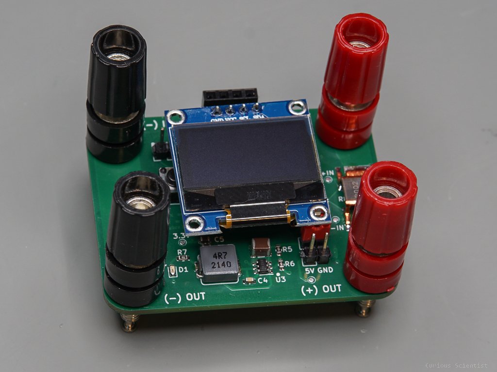
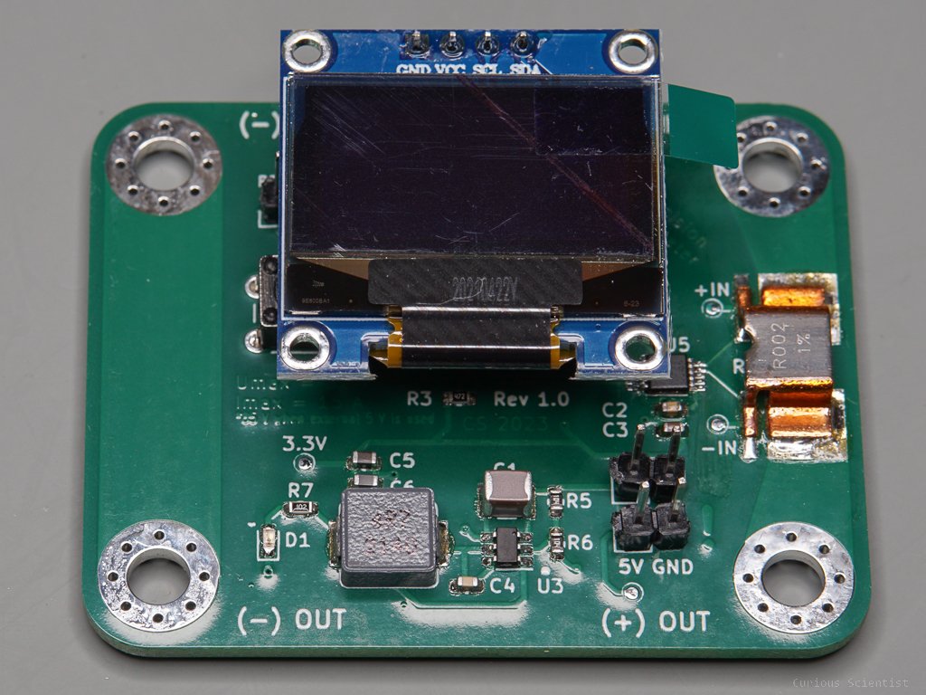
All these parameters (voltage, current and power) are shown on the display. Furthermore, the chip can measure its internal temperature (die temperature), so I also print that value on the display. This can be useful because the chip is relatively close to the shunt voltage and the power traces, so if those things get hot, the chip will also feel the temperature increase.
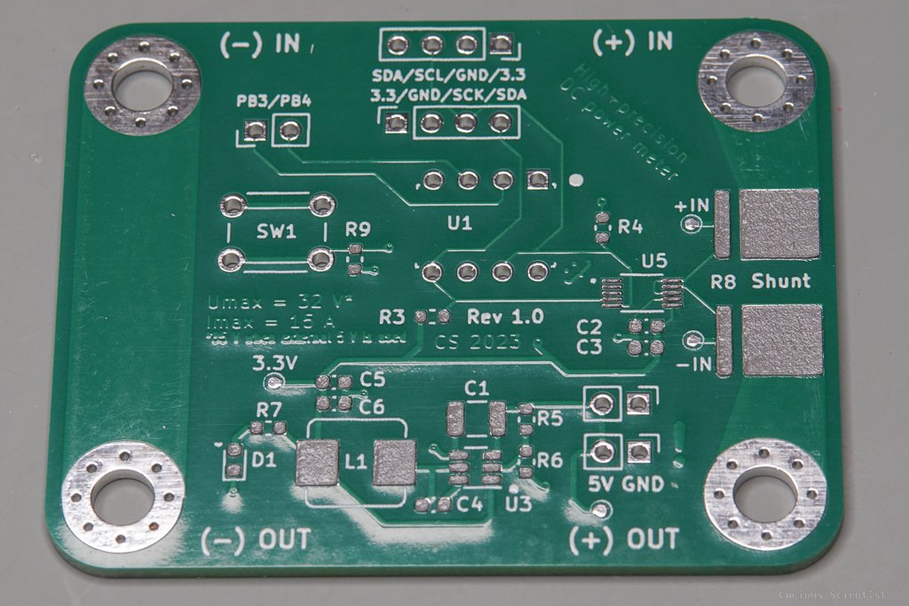
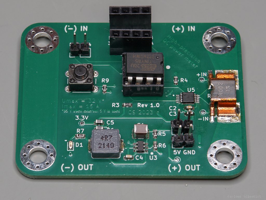
The board can be powered in two different ways. If we want to utilize the full measurement range up to 85 V, the board must be powered by an external power source. Preferably, 5 V, but in fact it can be anything between 3.8-32 V. In this case, the jumper pin next to the R5 resistor should be kept open. The other way is a “self-sufficient” mode. In this case, the board is powered directly by the bus voltage. In this case, the bus voltage must be between 3.8-32 V and the jumper pin next to the R5 resistor must be shorted. In this case, nothing should be connected to the 5 V pin!
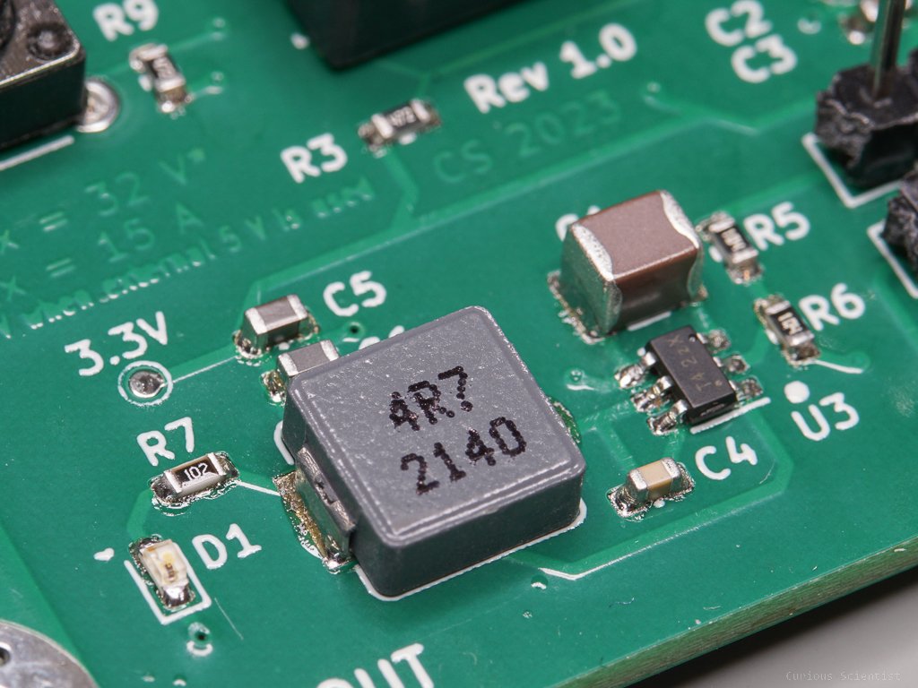
In both cases, this 3.8-32 V voltage range shows up. The reason is that this is the input voltage range of the onboard buck converter (AP63203). In both cases, we feed the buck converter, which then further reduces the voltage to 3.3 V to feed the rest of the circuit, but in one case, the input voltage of the buck converter comes from an external source, and in the other case, the measured power line supplied the input voltage. In my applications, I will mainly measure the power supplied for Peltier coolers which are typically fed with voltages between 5-15 V and currents from 1-15 A, so it is a perfect range to use the circuit in the “self-sufficient” mode.
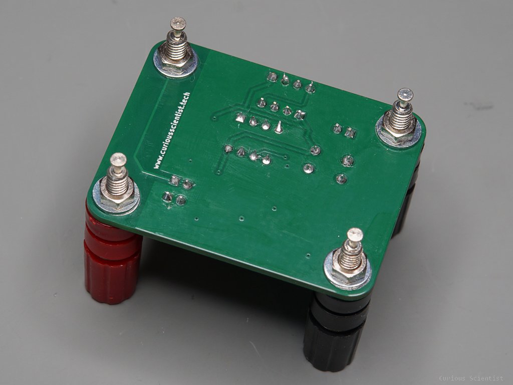
The PCB has four M4 holes with pads. As it is shown in the pictures below, it is perfect for using binding post terminals. But spade terminals or round terminals bolted to the PCB are also good. The current carrying traces on the PCB are wide enough to carry the max current (15 A continuous or 20 A for short periods), especially because the board is built with 2 oz copper thickness.
PB3 and PB4 pins of the ATtiny85 microcontroller are not utilized, so I brought them to a more accessible place. A third GPIO pin (PB1) can also be accessed if necessary. Currently, it is utilized for the onboard switch, but the switch and its pullup resistor (R9) can be removed and PB1 can be used too.
Originally, I designed the board to have the same outline as a certain LCD so I could make a good-looking and compact DC power meter. But I also wanted to be able to use the circuit with a smaller OLED display. Unfortunately, their pin layouts (VCC/GND/SCL/SDA) are not always the same. The large display has the SDA-SCL-GND-VCC pin sequence, and the OLED display has the VCC-GND-SCL-SDA sequence. This is why there are two headers for the displays on the PCB. One for the LCD, another for the OLED display. Unfortunately, the same OLED display can have different “carrier boards” and therefore it can have different layouts. The one I had at home when I built the PCB has a GND-VCC-SCL-SDA pin sequence, which does not fit any of my built-in headers. So, I made a little adapter board for the OLED display so I can use it until my proper displays arrive by post. I ordered several displays a long time ago, but the shipping is very slow. Finally, if you can give up on the compactness, the popular 16x2 or 20x4 LCDs with the i2c adapter are also great displays for this module.
Images and extra resources
Get the relevant parts using my affiliate links!
128x64 Large LCD module (ST7567S driver chip)
Join my YouTube membership!
Get the PCB from PCBWay!