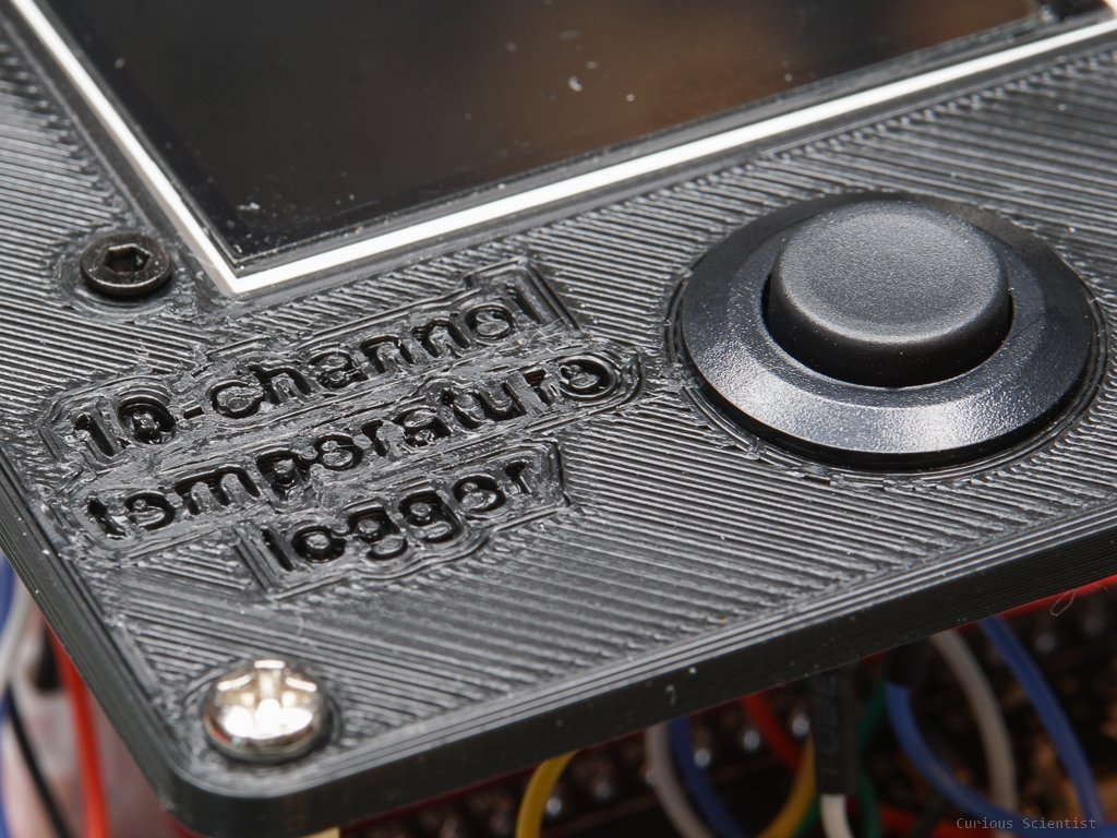
10-channel NTC-based temperature logger - improvements
In this video I show you a few cool improvements I did for my 10-channel temperature logger. Since the last version [link] I changed a few things which makes the logger better, and I also demonstrate a few tricks. I also talk a bit more about the basics of an NTC thermistor so the changes I implemented will make more sense.
Technical details
Let’s first start with the voltage divider. In the previous version, I used 10kOhm resistors for all ten thermistors. Since the nominal resistance of the thermistor at 25°C is also 10kOhm, at room temperature, the voltage divider will output half of the supply voltage. Decreasing the temperature of the thermistor increases its resistance, therefore the output voltage of the voltage divider will drop. Increasing the temperature will produce a higher output voltage on the voltage divider. Some examples are shown below.
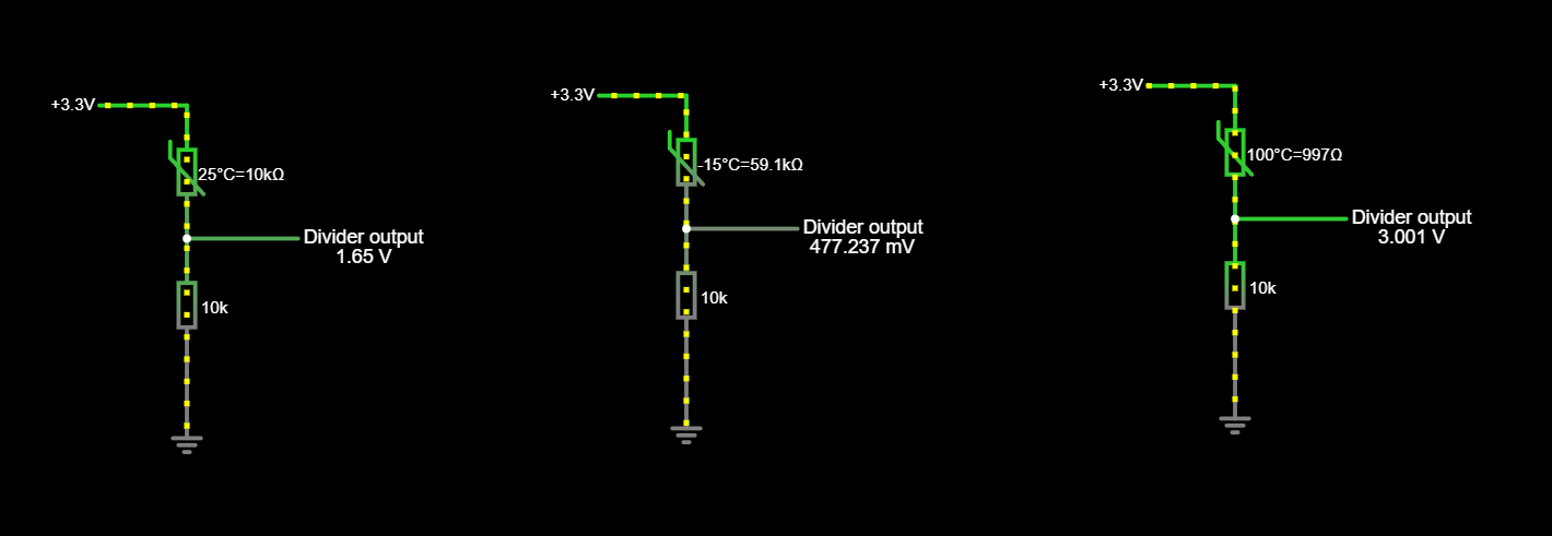
Output voltage of the voltage divider with different thermistor values. Please notice that R1 is the thermistor.
It is important to notice that I chose R1 (“top resistor in the voltage divider”) as the thermistor, and R2 (“bottom resistor in the voltage divider”) as the fixed value resistor. This choice implies that increasing temperature produces increasing output voltage. In the opposite case (R1 - fixed resistor, R2 - thermistor), increasing temperature would result in decreasing output voltage in the voltage divider.
Further looking into the principles of a voltage divider, we can determine its output voltage value using the following equation:

Then, we can go even further and start fiddling with the thermistor. Using the Steinhart-Hart equation we can predict the resistance of a semiconductor (thermistor) at different temperatures, or the other way around.

Using the equation directly can be a bit cumbersome because we need to solve three equations to get all three parameters. Luckily, there are good calculators on the internet for this purpose. This one from SRS only needs three temperature-resistance data pairs and it gives us all the parameters.
However, I want to create a formula that can predict the output voltage of the voltage divider at a given temperature. This is helpful because I can tune the value of the R2 resistor for my desired measurement range.
As a first step, I plotted a few points from the datasheet of my 3950 10k thermistor. The curve looks quite exponential, so I fitted an exponential curve on it.
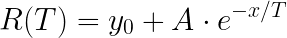
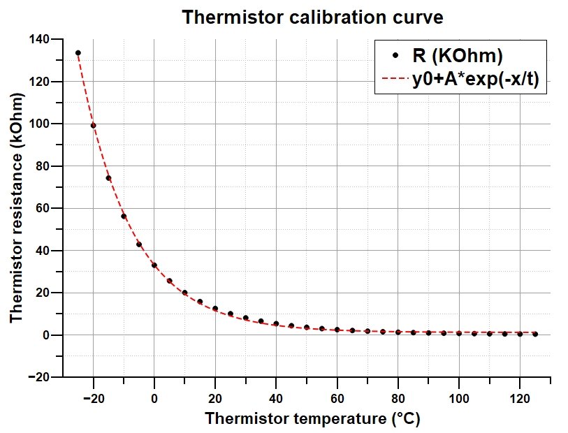
Then I got three parameters (these are not the same three as for the SH-equation!) that I can use in the exponential equation to get the resistance at any given temperature. So, now I can rearrange the voltage divider formula and substitute the R1 (thermistor) value with the equation.

This modification introduces temperature dependence to the equation. What I mean is that since R1 depends on temperature and temperature is the variable parameter, the output voltage of the voltage divider also becomes temperature-dependent. Hence, we can plot another graph which shows us the output voltage of the voltage divider as a function of temperature.

This graph is not only useful so we can see the expected output voltage, but it also shows where the curve is more or less linear. This is great because then we can decide if the chosen R2 resistor is the correct one to cover the measurement range with the linear part of the curve.
By replacing R2 with higher resistance resistors than the nominal value of the thermistor (10 kOhm) the curve gets shifted backwards thus the linear part of the curve covers more and more of the negative temperatures. Similarly, decreasing the value of R2 can shift the curve towards more positive temperatures.
However, it is worth noticing two important things:
The curve also gets skewed, so the linear part becomes shorter.
Lower resistance results in more current. Check, if your voltage source can handle the current draw!
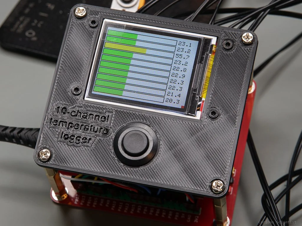
As it is seen in the video, I could not really test or show the effect of different R2 resistors in the voltage dividers. I think this is mainly due to the fact that I could not have a well-controlled temperature on every thermistors at the same time. I will come up with some better idea and I will test this feature again.
Get the relevant parts using my affiliate links!
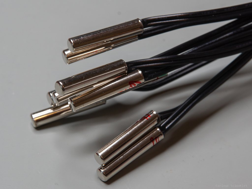
10k NTC thermistor probe - metal capsule
10k NTC thermistor probe - thin
Join my YouTube membership!
Get the PCB from PCBWay!