20 A 85 V Self-contained DC power meter - Improvements
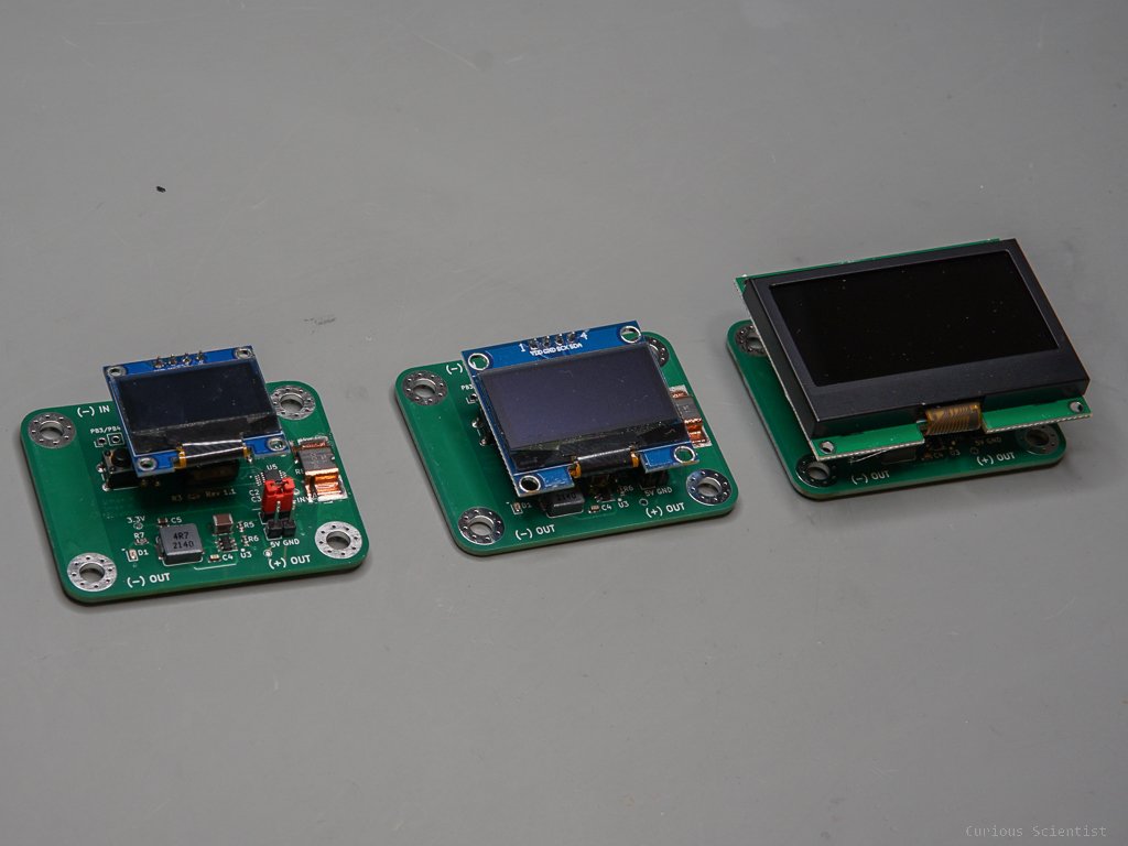
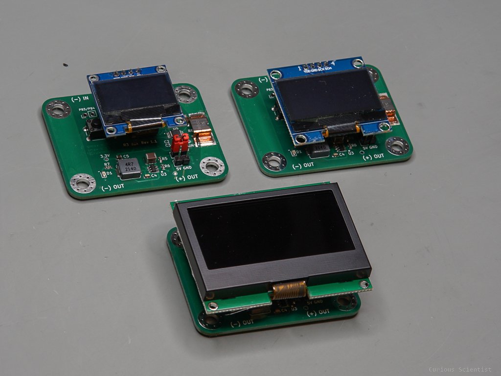
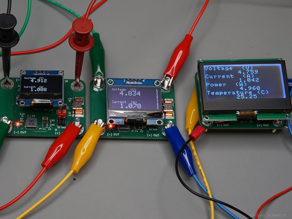
In this video, I show you the improvements to my DC power meter. In the previous video, I showed all the functionalities of the power meter and I presented the code written to operate the screen and communicate with the INA238 power meter IC. In this video, I present the power meter with 3 different displays, 2 OLED and 1 LCD units.
Additional resources
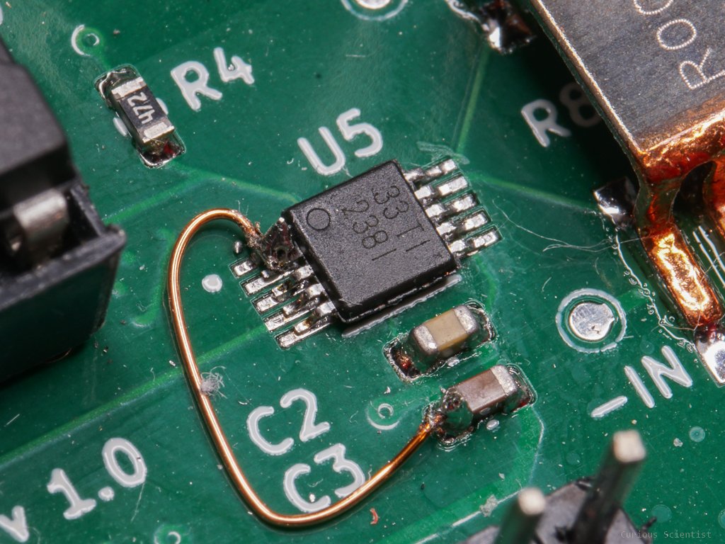
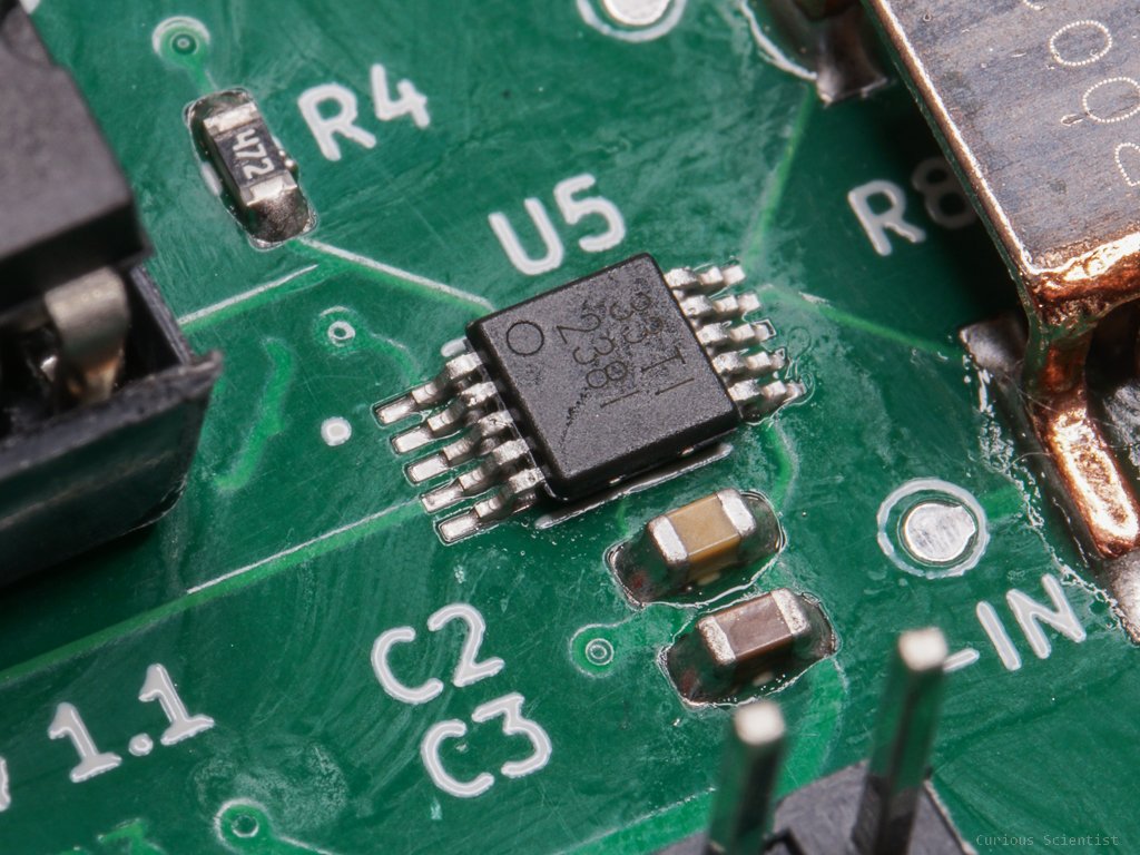
The new version (v 1.1) of the board contains a small “bug fix”. I accidentally left the address pins of the INA238 floating in the first version (v 1.0). It was not a big deal to fix it manually, but I wanted to publish a board without this issue, so people have no issues replicating my project. The address is permanently set to “10000000” by pulling both A0 and A1 pins to the ground (see Table 7-2 in the datasheet). Actually, this address does not matter as long as it is set because we only use one INA238 chip with the microcontroller anyway. But the address must be set and the pins cannot float.
I also received the LCD that I originally wanted to use with this board, so I could finally assemble the board with it. I also needed to write a new code for the LCD. The new code is, of course, explained in the video. Furthermore, I tested the board with a larger, 1.3” OLED display. It works well, however, I noticed a small glitch on the display and I don’t know if it is the display or it is the code. This needs a bit more inspection.
As you might notice, using the larger displays prohibit the user from adding binding post terminals to the board. If you need the binding post terminals, go for the 0.96” OLED. Just make sure that you purchase the one with the correct pin layout (VCC/GND/SCK/SDA). If you use the larger displays, you can attach fork or ring terminals to the board using an M4 bolt, a washer and a nut. If you want to make a permanent connection, this is anyway the best way in my opinion. Or, you can use alligator clips with the M4 bolts, in the same way I did in the 3rd picture in the gallery.
Join my YouTube membership!
Get the relevant parts using my affiliate links!
Get the PCB from PCBWay!