In this article, I show you how I built the new Z-axis for my motorised CNC microscope. In the previous video, I mentioned that there are still a few things that can be fixed on the microscope. One of these things, probably the biggest one to tackle, was a new Z-axis. Earlier, I designed a small attachment that allowed me to drive the Z-axis with a stepper motor via a timing pulley and a belt system. This worked, but the backlash was really bad, and the speed was also quite slow. Finally, I came up with a better solution that uses an SFU1204 ballscrew with the corresponding support bearings and a bunch of 3D-printed parts. This solution seems to be somewhat better than the belt drive system, and it allows a much faster and more precise positioning along the Z-axis.
Introduction
So, as I mentioned in the intro, the microscope already had a motorised Z-axis. I designed a 3D-printed attachment that sat on the top of the microscope and allowed me to mount a NEMA17 stepper motor in it. Then, I mounted a small pulley on the shaft of the stepper motor that then drove a belt and then the belt drove a larger pulley wheel that was directly attached to the coarse focus adjusting knob of the microscope. So, I just motorised the original focus-adjusting knob. It worked fairly well, but the backlash was a bit too much, and despite my efforts, I did not manage to entirely get rid of it. This caused an issue when I moved up and down along the Z-axis because the error due to the backlash slowly accumulated, and the distance along the Z-axis became less and less reliable and accurate.
This led me to the idea to change the Z-axis to something better, more accurate. I had a few SFU1204 ball screw kits (ball screw, ball nut, support bearings) at home, and since they are sturdy enough, I decided to make my design around such a kit.
What moves the microscope?
So, first, I removed the upper part of the microscope from the base. This was easy; it was just a set screw that held everything together. The base might already be familiar to you if you have been following my microscope adventures, because I showed in an earlier video how I mounted the X-Y stage on it. I designed and 3d printed an adapter that allowed me to mount the stage on the steel base. The X-Y stage has 6 equally distributed holes along a XX mm circle. So, I just designed a cylinder with holes on it, and then I extended it so that it fits the mounting ring on the base.
The stepper motor and its surroundings should also be familiar to you if you have been following the series. I 3D-printed a mount that sits on the top of the microscope and allows its focus knob to be driven by a stepper motor via a belt and some pulley wheels. It was a solid design, I would say, except for the backlash from the belt drive. It worked fairly well.
After removing the 3D-printed part, I also removed the metal part that has the focus-adjusting knobs. It simply slides off and reveals a nice brass dovetail. This dovetail allowed the microscope to move along the Z axis smoothly. The brass block and the dovetail are held down by three bolts, and to make sure that they are accurately sitting where they should, they also have what seems to be guiding/aligning pins. I just had to carefully pry the bits, and everything came off.
The painful revelation came then. The bolts were something non-standard. It was neither an M3 nor an M4, despite the fact that it looked fairly similar and its diameter was about 3 mm. It is probably an inch-thread or some M4 bolt with a weird thread pitch. I will never know because I decided to approach this problem with brute force. So, first of all, the microscope is supposed to be sitting on a 3D-printed attachment. The 3 screw holes were supposed to accommodate the screws that connect the 3D-printed attachment to the microscope. Therefore, since the screw hole was around 2.5 mm, and the drill size for an M4 tap is 3.3 mm, it seemed easy to expand the thread into a 3.3 mm hole and then cut an M4 thread into it. So, I took my little kit with the corresponding drill bit and tap and slowly made the holes. The body of the microscope is probably cast iron or something similar because it was very soft. It was easy to drill it and make the threaded holes. I was afraid that I was going to make wonky threads, but they turned out to be fine. The M4 bolt went in smoothly. With this, the mounting of the microscope to a custom holder was solved.
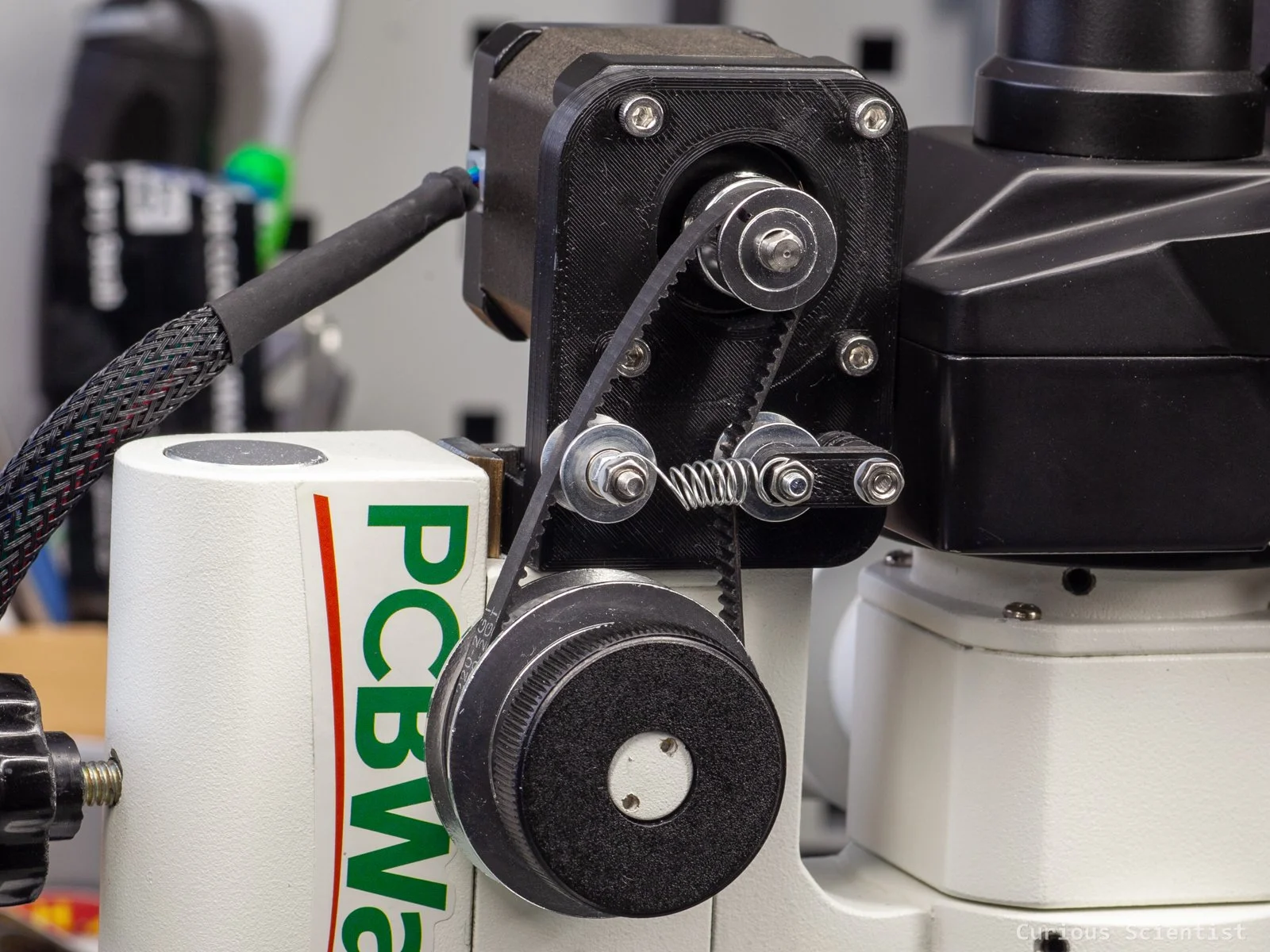
Previous Z-axis drive using a NEMA17 stepper motor and a belt drive system.
The three converted holes for supporting the microscope
The concept of the Z axis actuator
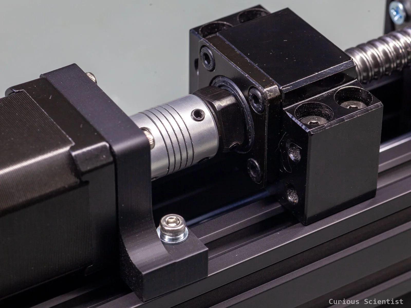
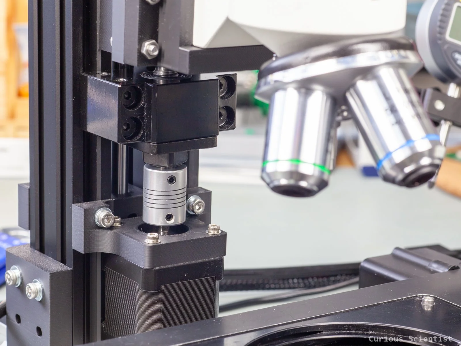
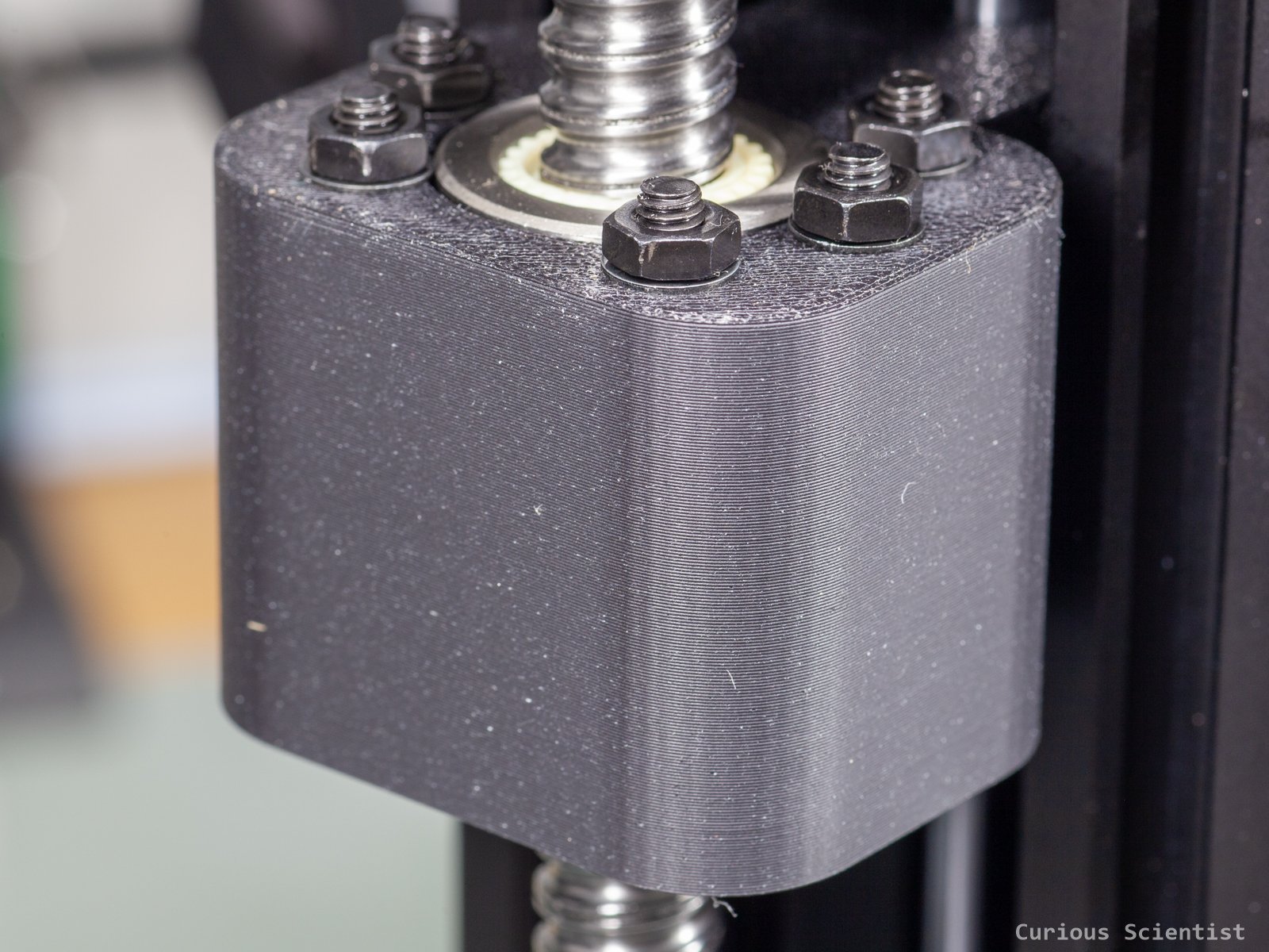
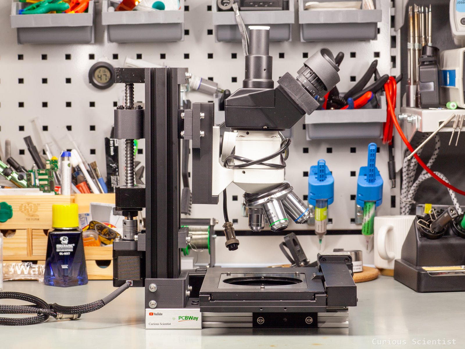
So, in the next step, I had to figure out how to move the microscope along the vertical axis. Since I had the parts lying around, I first created a proof-of-concept mechanism to study it. The mechanism is based on a simple off-the-shelf kit that is built around an SFU1204 ballscrew. So, there’s the ballscrew and its ballnut, plus two support bearings, one of which is a support-only bearing and is mounted at the end of the ballscrew and one which is also a thrust bearing and is mounted at the beginning of the ballscrew where the ballscrew is joined to some sort of driving mechanism. The stepper motor is connected to the ballscrew by a flexible coupling. Both bearings are attached to an extrusion profile, one profile on each side. The stepper motor sits in a 3D-printed flange. The ballnut received a 3d printed attachment that allows me to mount the previously shown microscope holder on it, and it also extends towards the bottom of the mechanism, where it is connected to an 8 mm shaft via a bearing to provide extra support and stiffness. Plus, this ensures that the microscope does not start to swing when the ballscrew drives the ballnut.
The actual actuator
After studying the mechanism, I wanted to make it stiffer, so I replaced the proof-of-concept 2020 profiles and used 2040 profiles instead. This should provide extra support against the bending moment created by the somewhat heavy microscope. Otherwise, everything else is the same as in the proof-of-concept mechanism. I slightly reworked the ballnut attachment and made it so that the front side of the ballnut sinks into the attachment. It just looks better, but functionally it is the same. The bearing is simply held in by friction. The hole for the bearing is a bit on the tight side, so one must use force to press it into the 3D-printed body.
The assembly process was a bit cumbersome because I had to make sure that everything sits straight and nothing gets stuck, or I don’t overtighten the bolts and crack the plastic parts. A lot of tightening and loosening was needed, but at the end, I think I managed. It is a bit pity that the hole-to-hole distance on the support bearings is a bit awkard and it does not match the extrusion profile’s dimensions. Otherwise, I would have mounted everything on the wide side of a single 2040 profile.
Once the linear actuator was assembled, I tested it by moving it by hand. The movement felt OK and everything seemed to move fairly straight. I could not feel anything being tight or stuck or similar.
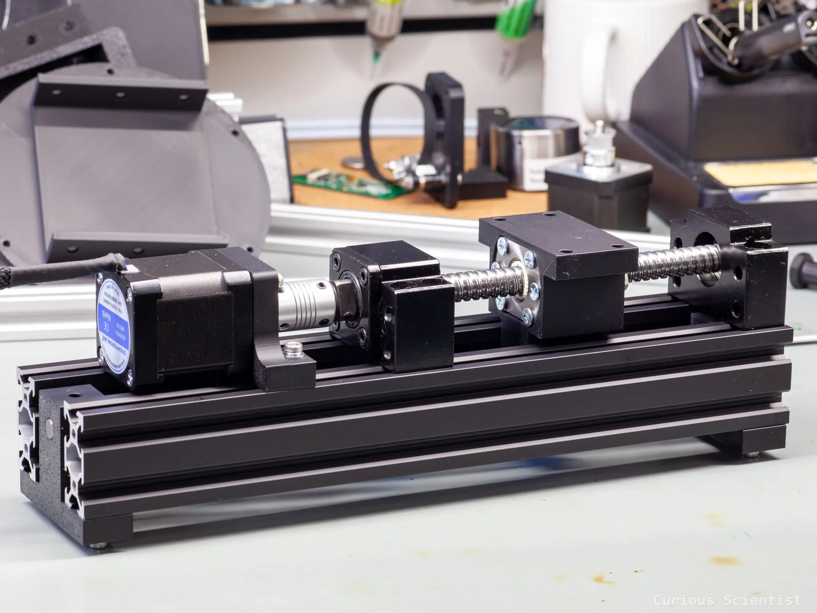
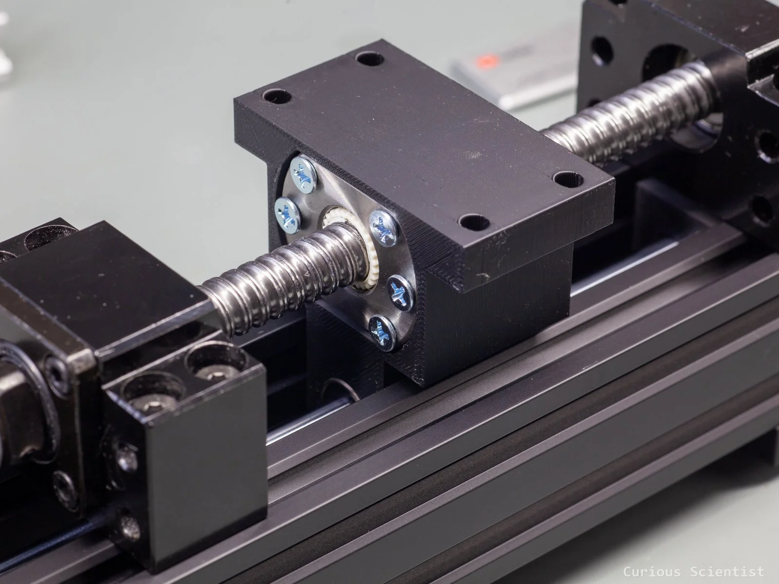
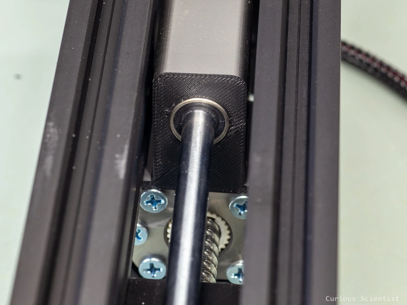
The assembly
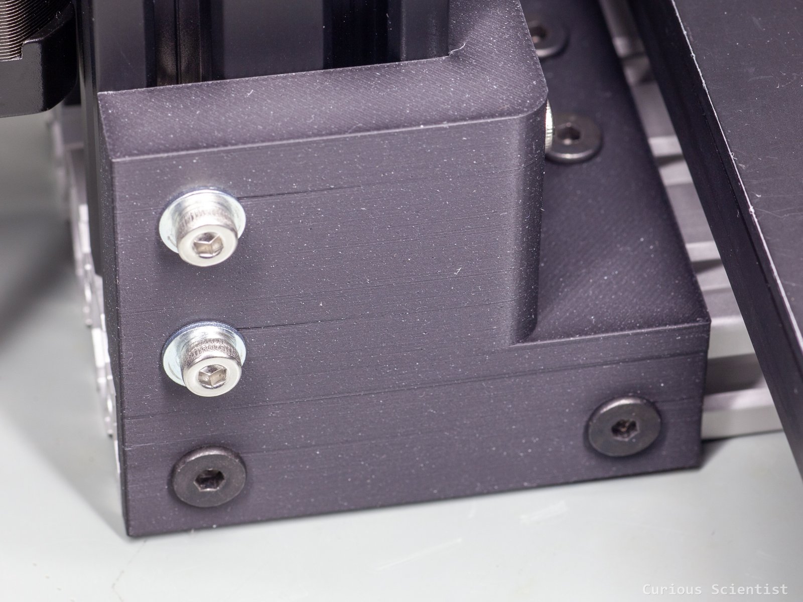
The next step was to connect the Z axis to the rest of the microscope. First of all, I did not reuse the original base of the microscope. It would have been too difficult to attach it to the Z axis. So, to keep it simple, I mounted the X-Y stage on a 2080 profile. Therefore, I have a 2080 profile lying on the desk, and two, vertical 2040 profiles holding the Z axis. Unfortunately, the Z axis profiles are a more than 40 mm apart from each other, so I could not use standard attachment to join the vertical axis to the 2080 profile. So, I just printed a joint. The joint tightly hugs both the vertical and horizontal profiles and there are multiple bolts and nuts holding everything together. I used a relatively large wall thickness, so the structure is hopefully stiff enough.
After mounting the Z axis, I also had to place the stage on the 2080 profile. This was done via the previously introduced 3D-printed adapter. It is attached to the 2080 profile by bolts and nuts and it is attached to the X-Y stage via four bolts (although, there are six holes, just in case). After finishing joining the adapter and the X-Y stage, I just placed the whole thing on the 2080 profile, but I did not fix it yet because the microscope also has to be mounted on the Z axis and then the X-Y stage must be centered accordingly.
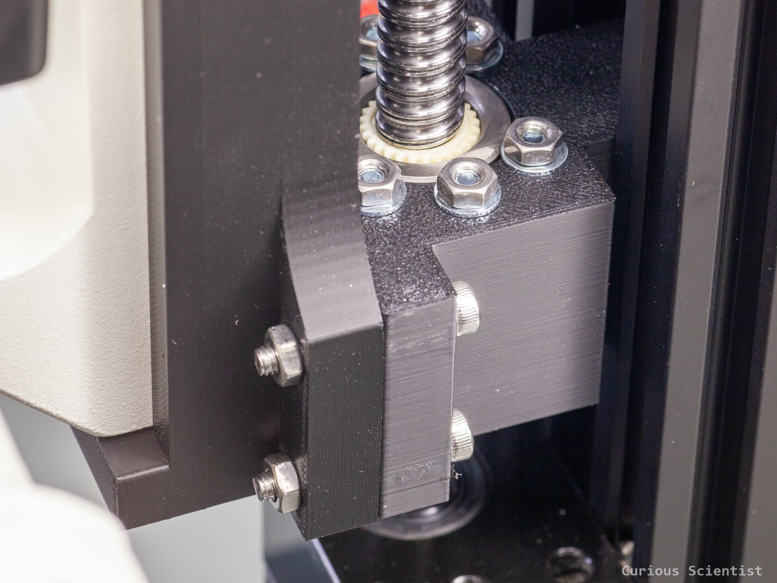
The mounting of the microscope is done via a mounting piece that is attached to the previously prepared three M4 holes. The 3D-printed holder tightly slides onto the microscope. I created a groove on the support, so the microscope’s attachment is supported from the bottom and from the side. To get some interesting numbers, I measured the microscope’s weight. It was 2366 g. This is the weight that the Z axis should be able to support and move up and down.
Testing the accuracy
To test the accuracy, I first measured the “accuracy” of the positioning with a dummy microscope holder but without the microscope. The microscope holder is perhaps 40-50 g, so it does not influence the outcome. I just needed it, so I could attach the tip of the dial gauge to the moving part. At this point, the controller was not programmed according to the ballscrew, so the clicks on the CNC pendant did not directly translate into a totally proportional displacement. What I did as a test was the following: I tared the dial gauge, and then turned the pendant wheel 100 clicks in one direction, then 100 clicks in the other direction while the multiplier was set to x100. The dial gauge I used has 0.01 mm resolution.
Due to the tiny flexing of the whole setup and the too-hard buttons on the dial gauge, I could not make the zero exactly 0.00 mm, but I tried to be as close as possible. I tested the setup multiple times in both directions. I started to move upwards, and after 100 clicks, the dial gauge showed 6.68 mm. Then, went down and up and so on a few times to see if the values creep. Then, at the “0” position, I moved down and up and so on a few times to see how the values developed. There was a visible difference, but this was only visible on the dial gauge, because the values only differed by 40-50 um. This is basically the thickness of a human hair, so it is not exactly easy to see on this setup if it is off by such a small amount. However, this amount can matter under the microscope!
Then, I repeated a similar procedure with the microscope sitting on the mechanism. This was a bit more difficult because it was hard to find a good place to put the measuring tip of the dial gauge. Apart from moving up and down 100 clicks, I moved up and down a few hundred clicks, plus I also changed the multiplier. The deviations were the same, in the order of magnitude of 40-50 um. So, the mechanism and the motor have no issues lifting and carrying the microscope.
Support me by buying the relevant parts using my affiliate links!
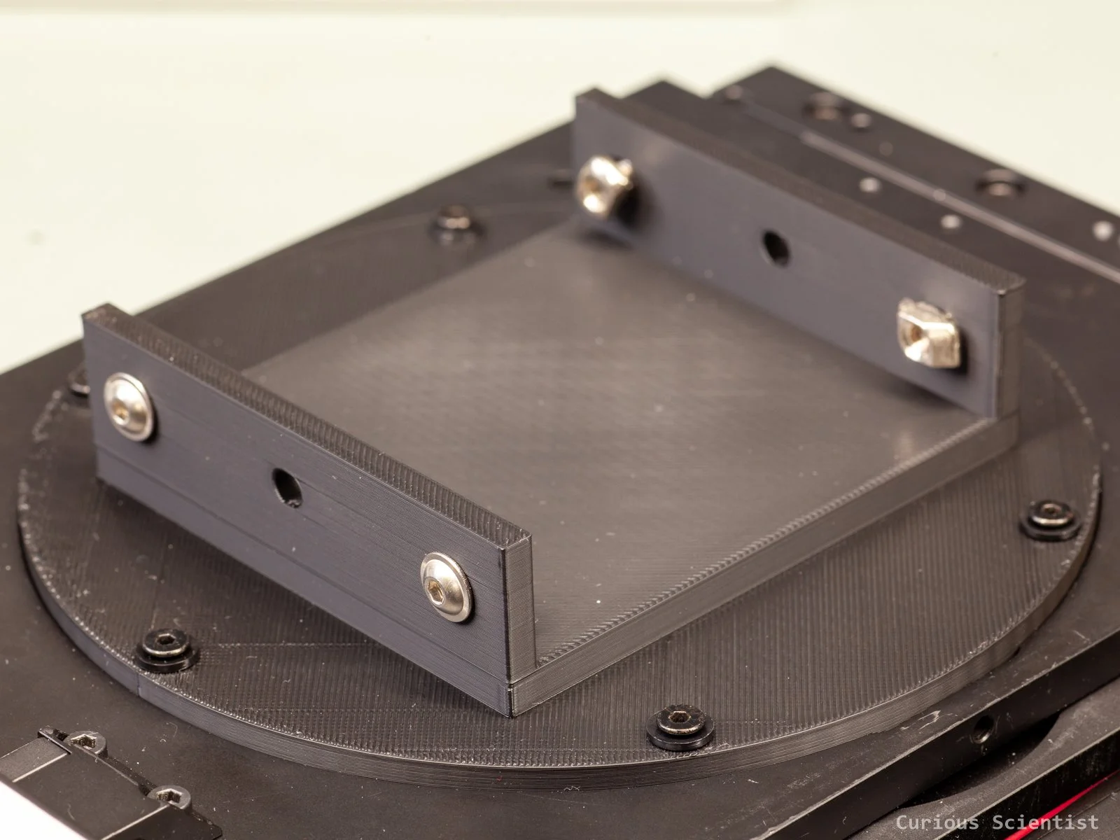
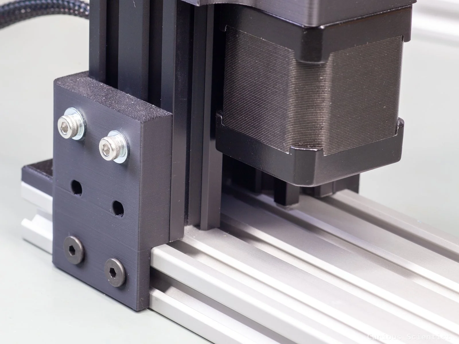
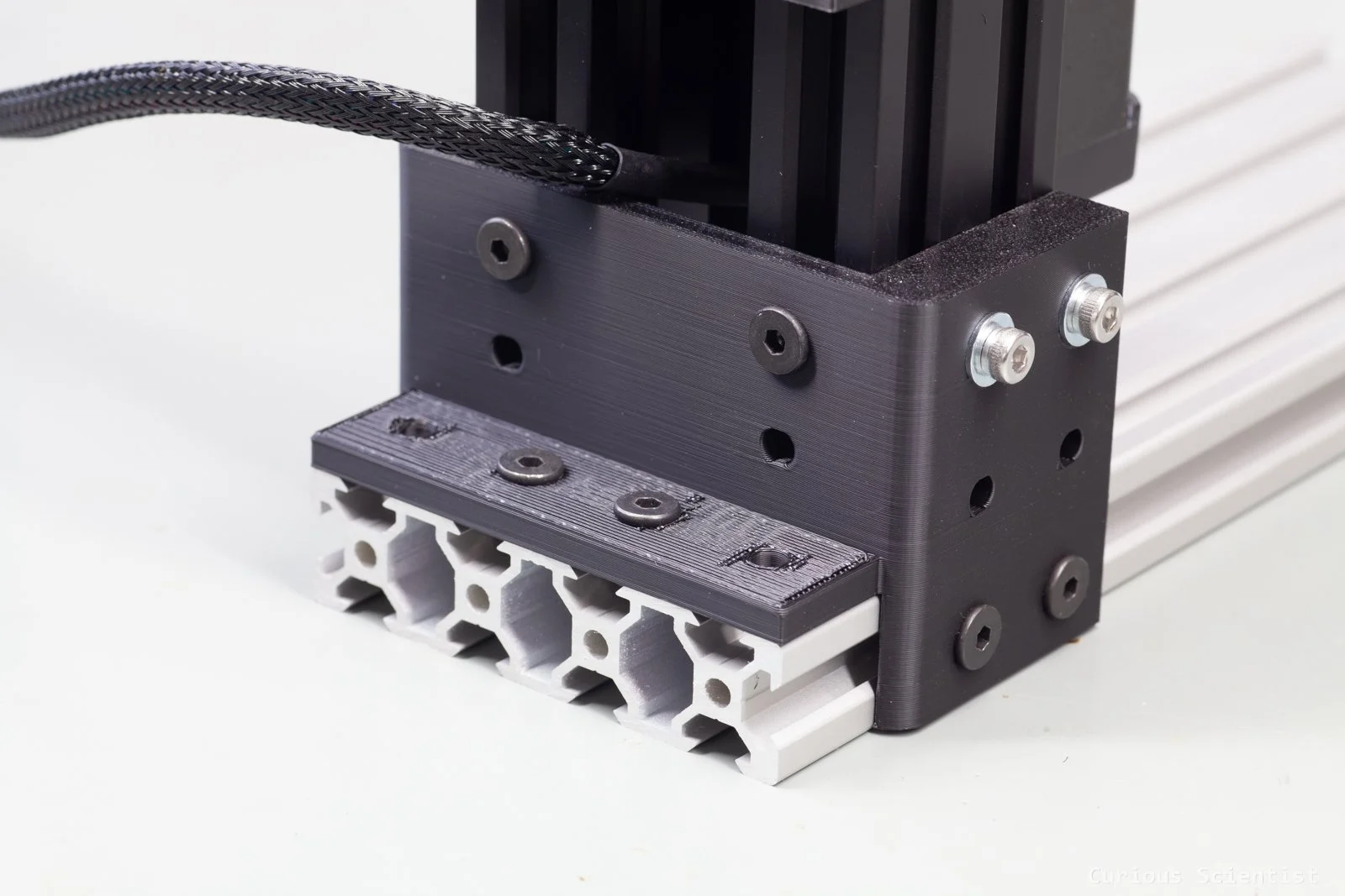
The initial microscope support. It is attached to the actuator by four bolts.
A hiccup!
Sure enough, I made a mistake in the design process and I only noticed it after I assembled everything. When I designed the setup, I forgot to consider the height of the turret of the microscope. Therefore, I could not move the microscope close enough to the subject. So, I redesigned the microscope holder and printed a new one. I made it a bit taller and I moved the mounting holes up by ~90 mm. This way the lenses could be operated within their working distance.
After resolving the hiccup, I connected the controller to my computer, reprogrammed it with the correct parameters according to the ballscrew’s pitch and then tested it. I just moved the Z axis to random positions and distances to see if it really goes there. Since the positioning only relies on the number of steps and the pitch of the ballscrew, and there are no encoders, because it is an open loop system, I used the dial gauge again to check if the Z axis goes to the requested locations. In my opinion, it performed well.
But wait, there is more!
So, after the test series, I reworked the crosshead that connects the ballnut, the shaft and supports the microscope. I mirrored the components, so the stepper motor and the ballscrew and its accessories were mounted on the other side of the profile, “behind” the whole structure. The 8 mm shaft stayed between the profiles and the microscope also stayed where it used to be, of course.
Why did I need this? I discovered, that the Y axis of the X-Y stage was sitting nearly at its maximum position while it was almost hitting the stepper motor. This meant that when I brought the X-Y stage to its physical center, the subject at the center of the stage was not under the microscope lens, but far away from it. To bring the subject under the lens, I had to go very close to the maximum of the Y axis. So, I lost quite some range along the Y axis. To improve it at least by a few centimeters, I put the stepper motor to the other side, so I could bring the X-Y stage closer to the extrusion profiles of the Z axis.
Another reason why I flipped the arrangement is because when I moved the microscope along the Z axis, the image was shifting a bit. I could see that the microscope was picking up the movements of the ballscrew. It was not too much, but I was hoping that if I put the load on the other side, I could make it better. The new arrangement helped to stay at the centre of the image, but there was noticeably more vibrations. I assume that this is due to the fact that the 2.3 kg microscope is hanging on a longer lever arm which is, despite the additional 8 mm shaft, not stiff enough. This is of course understandable, but it worth a try.
All in all, I think I am moving in the right direction with the Z-axis, but I will revisit the topic very soon. I want to fix this thing properly, so I can consider it done and I can move on to the next project. Especially, because the previous, original Z-axis mechanism was quite smooth and vibration-free. It just suffered from backlash and the focusing was considerably slower.
In the next iteration, I will use a mechanism with a stiffer base and with a stiffer linear actuator. Most probably, something with linear rails and bearings, and a similar ball screw. I will also try to avoid 3D-printed parts in the main load-carrying chain and, for example, use a stiff aluminium plate to attach the microscope to the new linear actuator.
If you found this content useful, please consider joining my YouTube channel’s membership or leaving a donation.
Also, please consider using my affiliate links when buying relevant gadgets.