Motorizing the Z (focus) axis on my metallurgical microscope
In this video, I show you how I designed and built an attachment for my Radical 2000x metallurgical microscope which allows me to adjust the focus with a stepper motor. This not only results in a smoother focusing operation, but it also allows to automate focus stacking. This video and article discuss the technicalities of motorizing the Z axis. The focus stacking part will be addressed in an upcoming article, due to its complexity.
Technical solutions
There are several smart solutions in this project. Due to the nature of how the microscope moves when I turn the focusing (Z adjust) knob on it, and the lack of space, I had to come up with some smart solutions.
First, let’s start with the Z adjust mechanism itself. In my previous article, I showed the microscope and I mentioned that the Z-axis can be adjusted by two knobs. There is a larger knob which adjusts the Z-height with coarse step size, and there is a smaller knob with a scale on it that adjusts the Z-axis on a finer scale. One division on the fine knob is 2 um vertical displacement on the Z-axis. There is no division on the coarse knob, but one full turn results in ~18 mm vertical displacement.
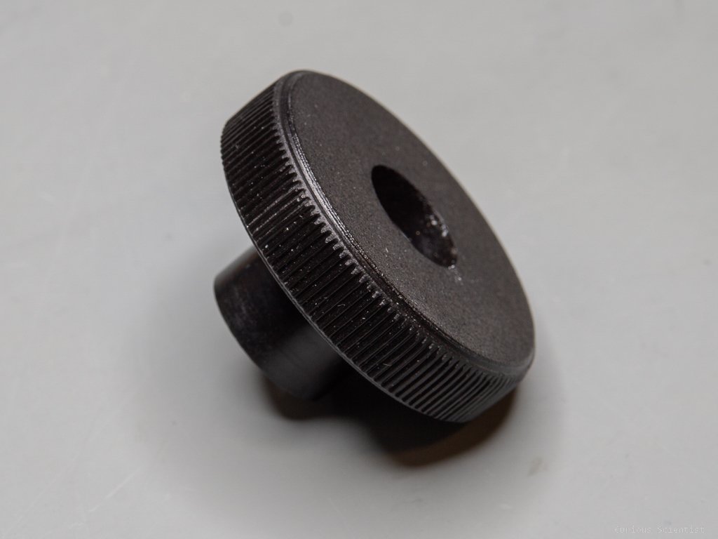
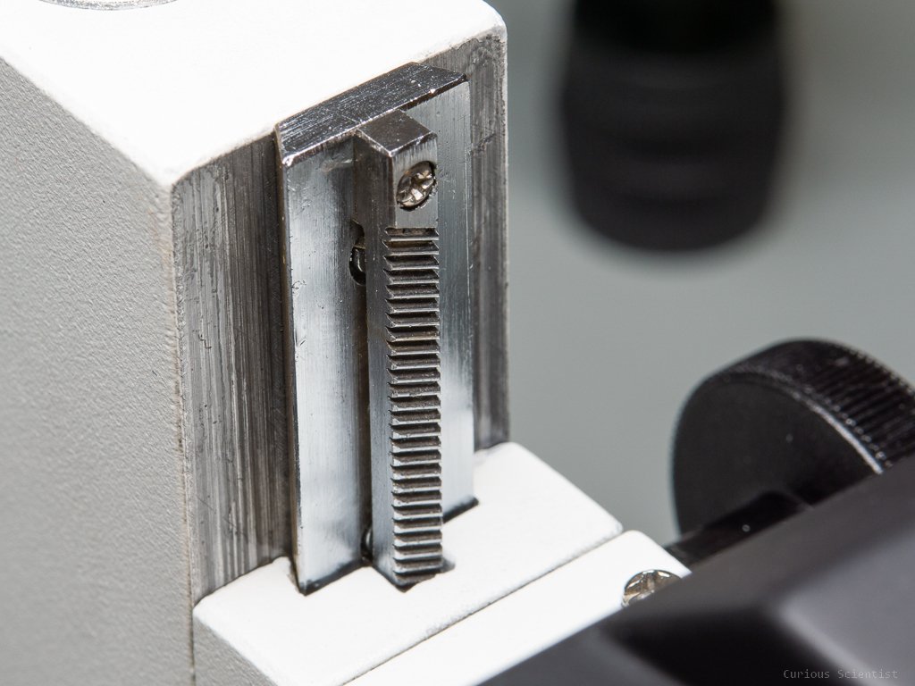
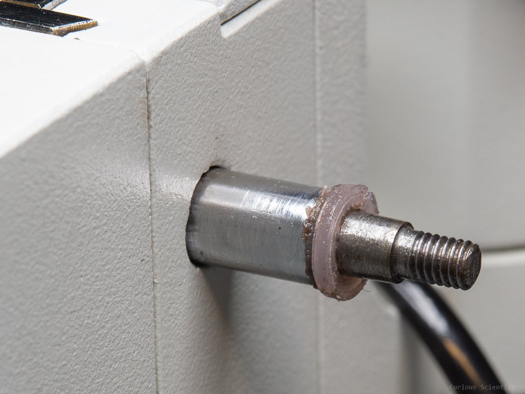
I decided to motorize the coarse Z adjust knob because, with a stepper motor, I will anyway be able to produce tiny and accurate enough steps. The Z axis is moved up and down by a rack and pinion mechanism. The rack (linear gear) is stationary and is attached to the stand, and the pinion (circular gear) is attached to the shaft of the Z coarse adjust knob. So, I had to figure out a way to rotate the knob. The inner part (shank) of the knob is roughly 10 mm wide and 16 mm in diameter. I had a 2GT 60 teeth pulley wheel at home, however, its bore size was not 16 mm. So, I drilled the pulley’s bore with a 16 mm bit which produced a nice snug fit with the shank of the knob.
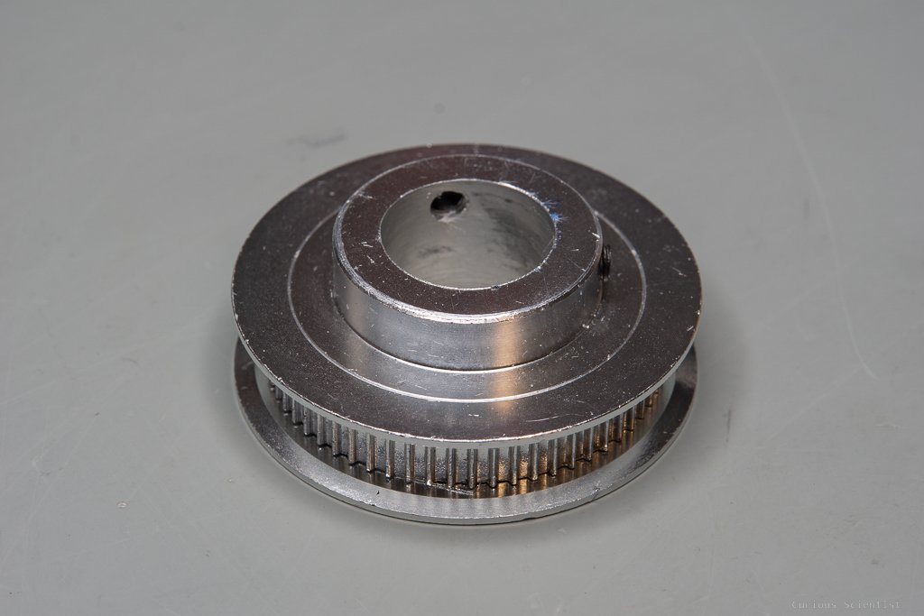
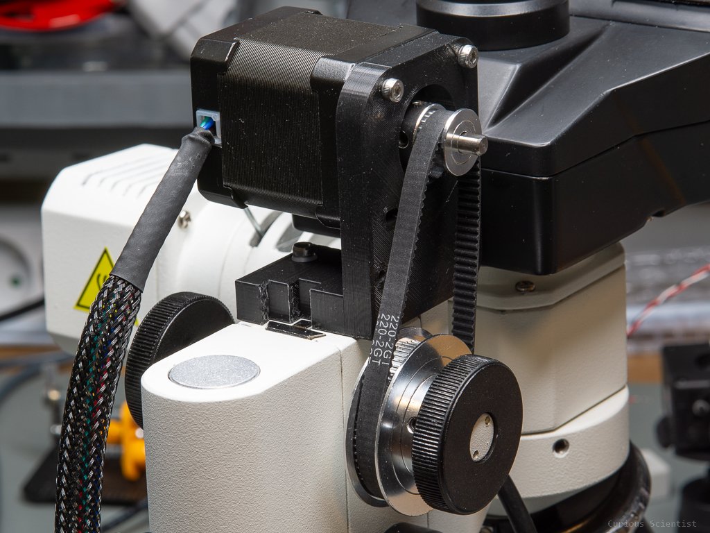
The next part is to figure out how to drive this wheel. Luckily, the 60 teeth pulley was a part of a kit I bought earlier. So, I also have a 220-teeth long timing belt and a 20-teeth pulley. The two wheels with the belt on are roughly 68 mm from each other when the belt is tight. Since the ratio of the teeth number of the pulleys is 60:20, I also get a 3-times increase in torque, but also a 3-times decrease in speed, but I don’t need speed in this project, so it is fine. I picked a stronger NEMA17 stepper motor with 59 Ncm (0.59 Nm) holding torque. With the leverage provided by the pulley system, I get 1.77 Nm torque. Since the knob is hard to move by hand because it basically moves the whole microscope (nosepiece, heat, camera…etc.), this torque was necessary.
Based on the previously mentioned vertical displacement of the microscope upon one full turn of the Z-adjust knob, we can convert the number of steps done on the motor into the amount of displacement in micrometres on the Z-axis.
We can start from the basic 200 steps/turn microstepping. It takes 200 steps to make a full turn on the main shaft of the stepper motor. This is where the 20-teeth pulley is installed, too. Then, this 20-teeth wheel is connected to a 60-teeth wheel. This means, that the motor has to turn 3 times to make a full turn on the 60-teeth wheel. Therefore, stepping 600 steps results in moving the Z-axis by 18 mm. Thus, 1 step is 18 mm / 600 steps = 0.03 mm/step, or 30 um/step. 1 step of the stepper motor moves the Z-axis by 30 microns. Remember, the fine Z-adjust knob’s resolution is 2 um/div, so it is 15 times better!
Let’s increase the microstepping to 3200 steps/turn. In this case, 9600 (3x3200) steps will move the Z-axis by 18 mm. Therefore, 18 mm / 9600 steps = 0.001875 mm/step, or 1.875 um/step is the resolution. Obviously, this won’t be repeatable, but it is a small enough step size to be able to use the coarse Z-adjust knob and have precise control over the focusing. A larger microstepping is also a nice thing to use because it makes the motor more silent. Furthermore, if I really want, I can push the microstepping to 6400 steps/turn which would take the (theoretical) resolution to the nanometer range.
To be able to mount the motor on the microscope, I had to be a bit inventive. Due to the fact that the Z-axis moves up and down, the best option was to put the motor on the same part of the microscope that moves up and down so the belt tension could be constant during the movement. If I had mounted the motor somewhere at a static point of the microscope, the pulley-to-pulley distance would have changed while adjusting the Z-height. This would have caused too loose or too tight timing belt while moving up and down along the Z-axis.
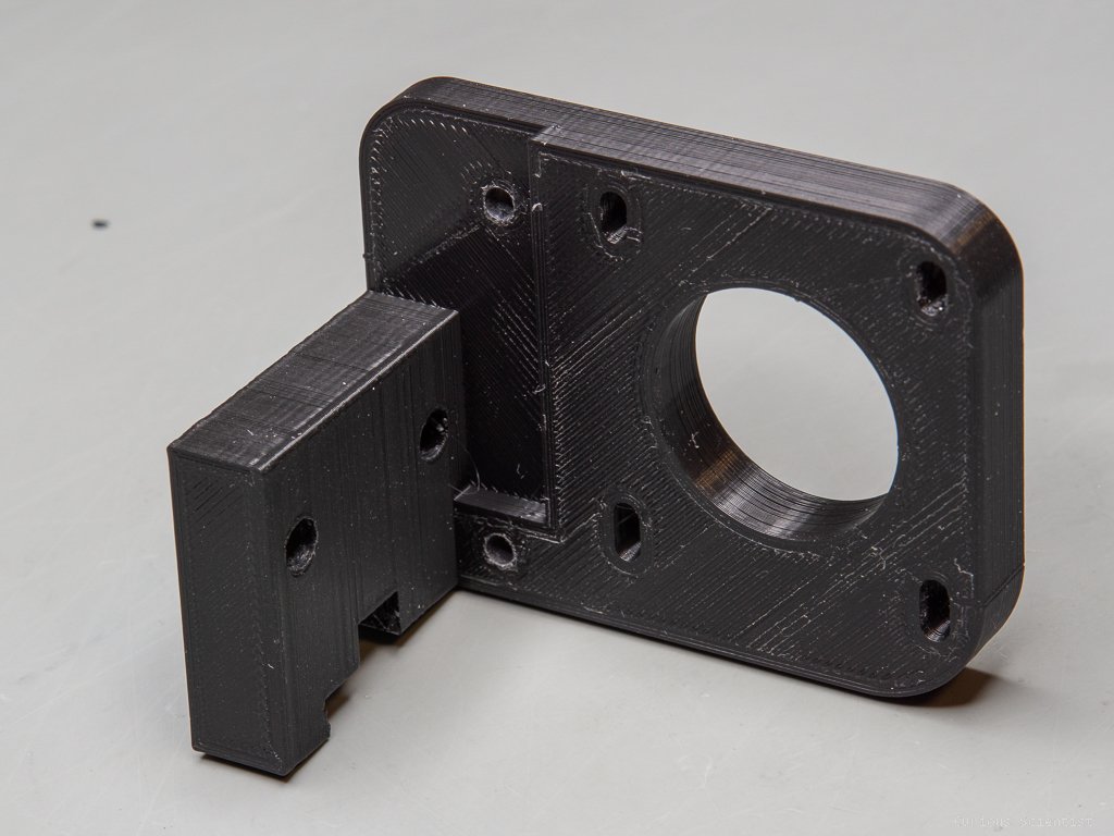
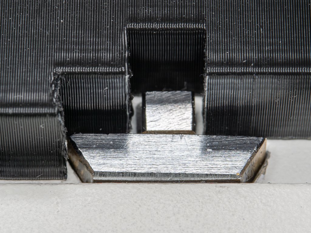
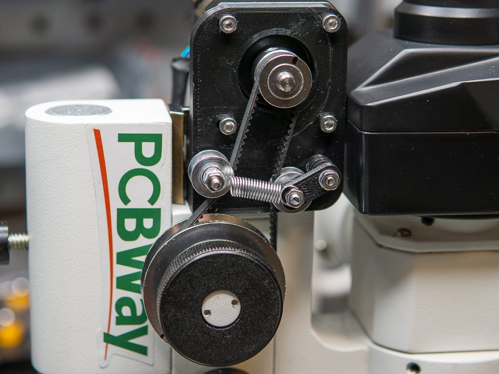
Luckily, there are two bolts on top of the part where the knobs are located. They support a lid which has a spring underneath. I do not know its exact purpose, but I suspect that it is some sort of tensioner for the Z-axis. So, I simply removed these bolts, put the 3d-printed piece on top of the lid and then fixed it with longer screws. So the lid was in place again, the spring was compressed down, and now I also had the motor bracket in place. The motor bracket went through a few (3) iterations in order to optimize the position of the stepper motor. I also invented a little belt tensioner mechanism that ensures that the timing belt is always tight and no steps are lost. However, there is still some slack in the system. This is very noticeable when I change directions. The motor has to move quite some steps until the focus starts to go in the other direction.
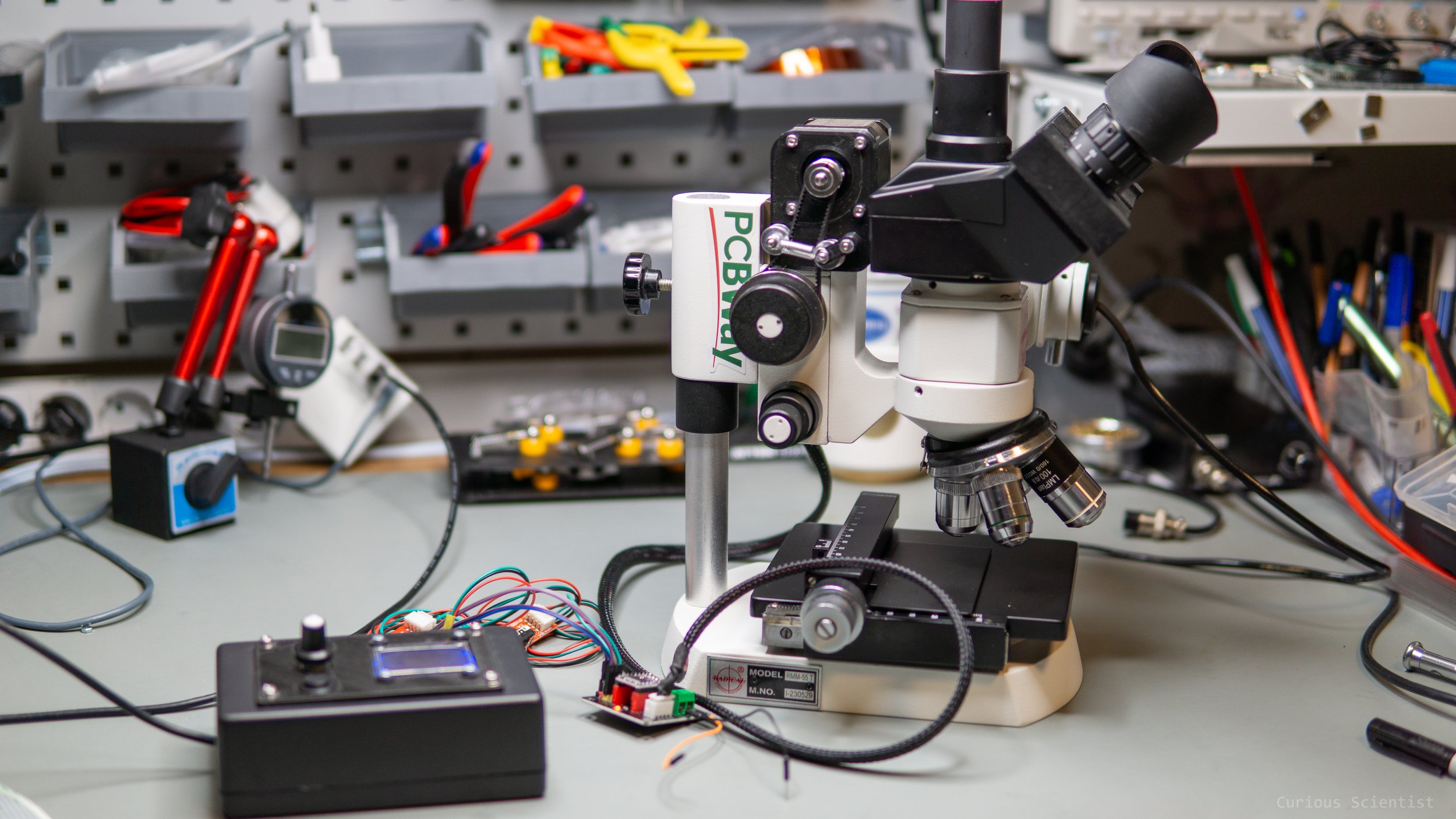
Once everything is assembled, I could test the motor. I used my custom stepper motor controller panel to drive the motor via the DRV8825 stepper motor driver. This allows me to move the motor step-by-step or in any custom way. I could make repeatable experiments on precision or cool focusing videos and so on.
In the next part, I will build the X-Y stage together with a custom-designed PCB that allows to control of any stepper motor-based X-Y-Z motorized mechanism.

Microscope’s Z-adjust knob with the 60 teeth GT2 pulley installed on it.

3:1 (20t:60t) gear ratio pulley wheel kit with timing belt. Notice the large (16 mm) bore on the 60 teeth pulley wheel!

Custom designed, 3d printed motor (NEMA17) holder
More resources
Get the relevant parts using my affiliate links!
DRV8825 stepper motor driver breakout board
Join my YouTube membership!
Check out PCBWay’s webpage!