XYZ Motorized Metallurgical Microscope
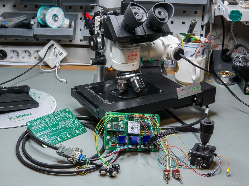
In this project, I show you my fully motorized metallurgical microscope. In an earlier project, I added a stepper motor and a mechanism to my microscope’s Z-axis to be able to adjust the focus electronically. This project expands the capability of my microscope. With the help of a high-precision motorized XY stage and my new, 3-axis stepper motor controller, I can control all axes with stepper motors. Thanks to the capabilities of the controller I built, I can move the axes with buttons, a joystick, or even by commands sent to the microcontroller from a computer via USB.
Additional information
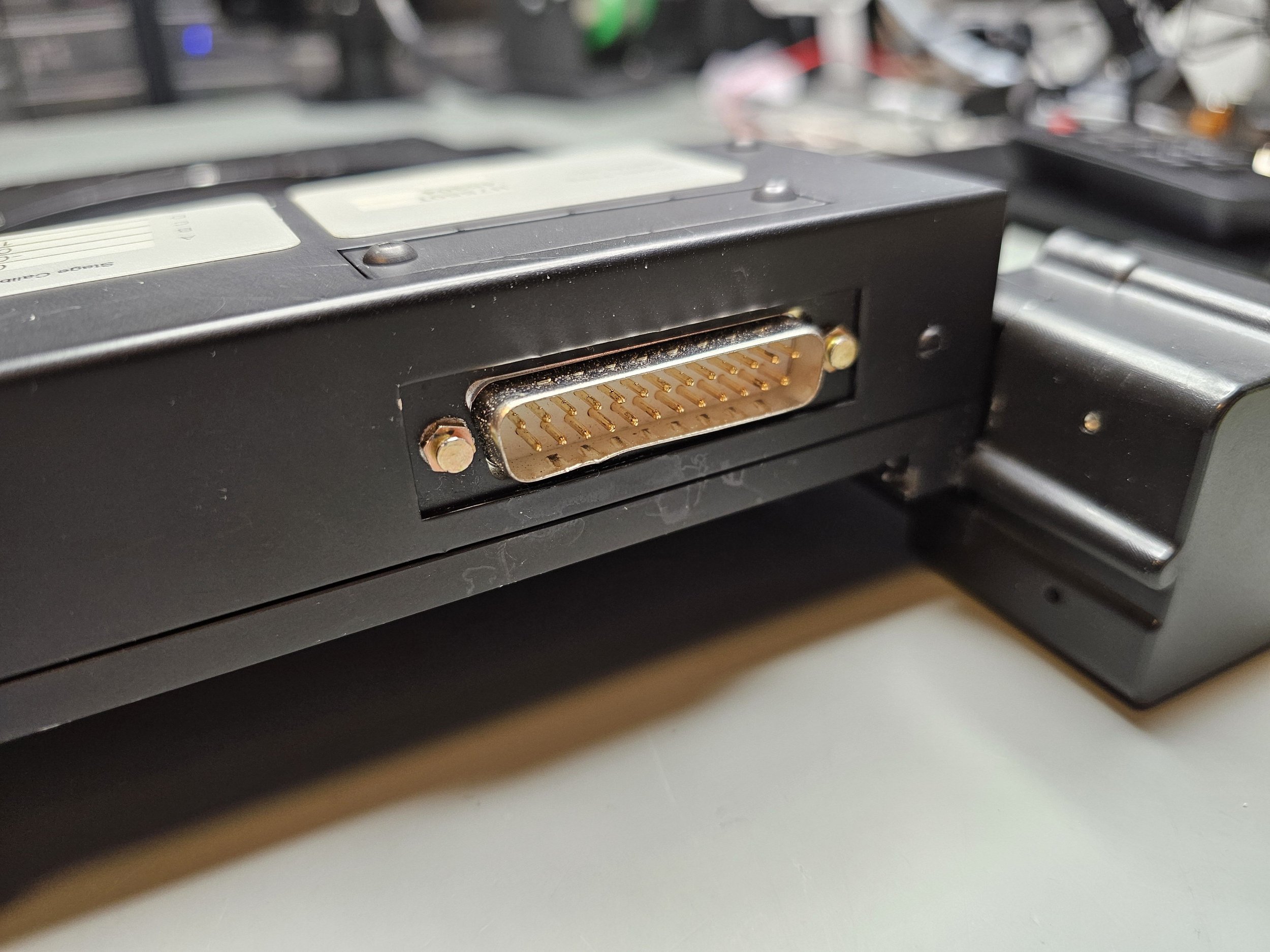
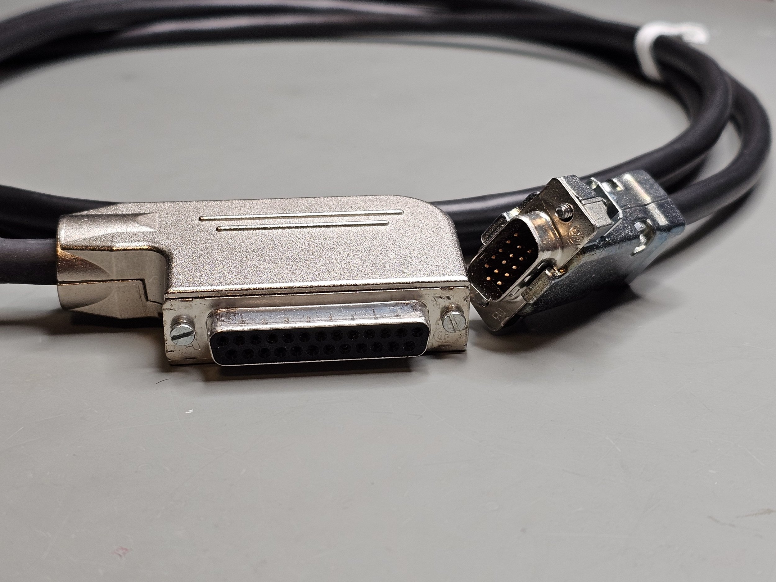
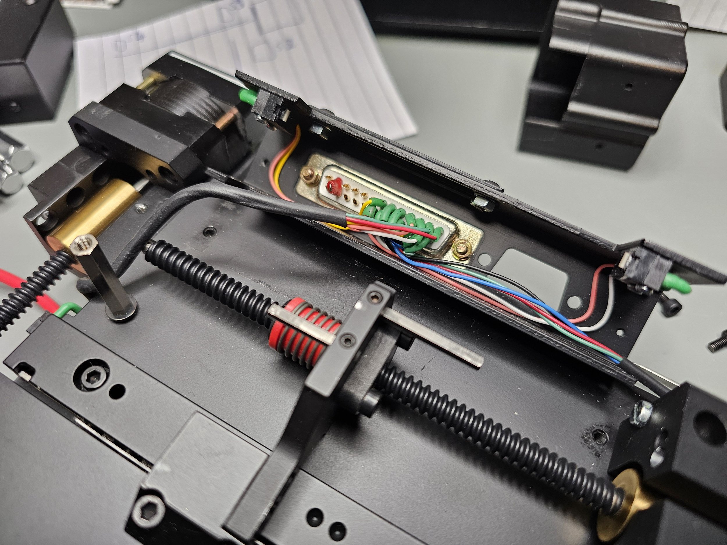
The XY motorized stage originates from a Thermo Scientific Nicolet FT-IR Continuum microscope. I located an eBay listing showcasing both the microscope and the separate stage. However, I mention this eBay listing only for its relevance. The stage came with a cable, featuring a 25-pin D-sub connector on one end and a 15-pin high-density D-sub connector on the other. This cable powers the two stepper motors and manages the signals of the four limit switches. Each motor is equipped with two limit switches, serving dual roles as both limit and homing switches.
Limit switches stop the motor upon activation to prevent movement beyond a certain point, while homing switches establish a reference point, typically setting a zero position for the mechanism. Each stepper motor drives a lead screw with a 2 mm pitch, meaning one full rotation results in a 2 mm linear displacement. The lead screw attaches to the stage via a spring-loaded anti-backlash nut, which is particularly advantageous for directional changes. With the spring-loaded nut ensuring continuous contact between the nut and lead screw threads, theoretically, no steps are lost. Additionally, the lead screw is coated with PTFE (Teflon) to reduce friction and ensure smoother movement.
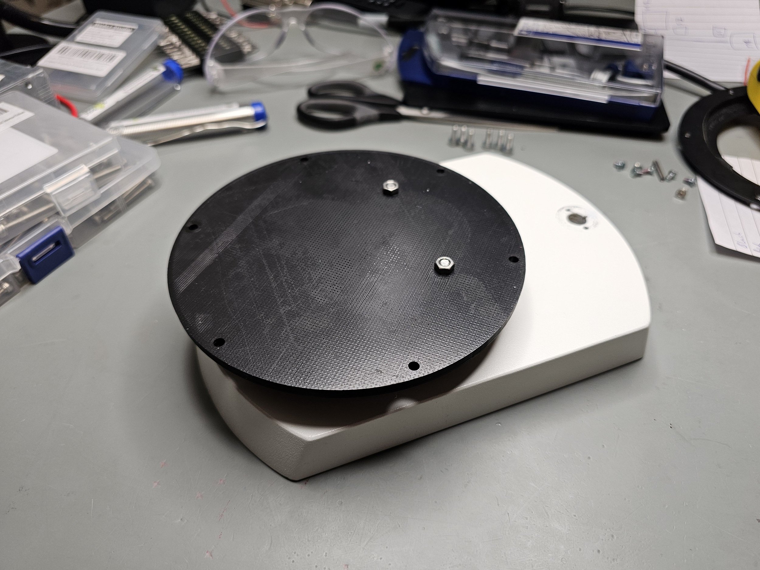
To mount the stage onto the microscope, I crafted a custom adapter using 3D printing. Firstly, I removed the old mechanical stage from the microscope's base and carefully measured the dimensions of the ring on the base plate. With these measurements, I designed an adapter tailored to fit the ring perfectly. Afterwards, I 3D printed the adapter to ensure a precise fit between the ring and the adapter, as well as between the adapter and the stage. Additionally, I printed another part specifically designed to hold glass slides securely in place.
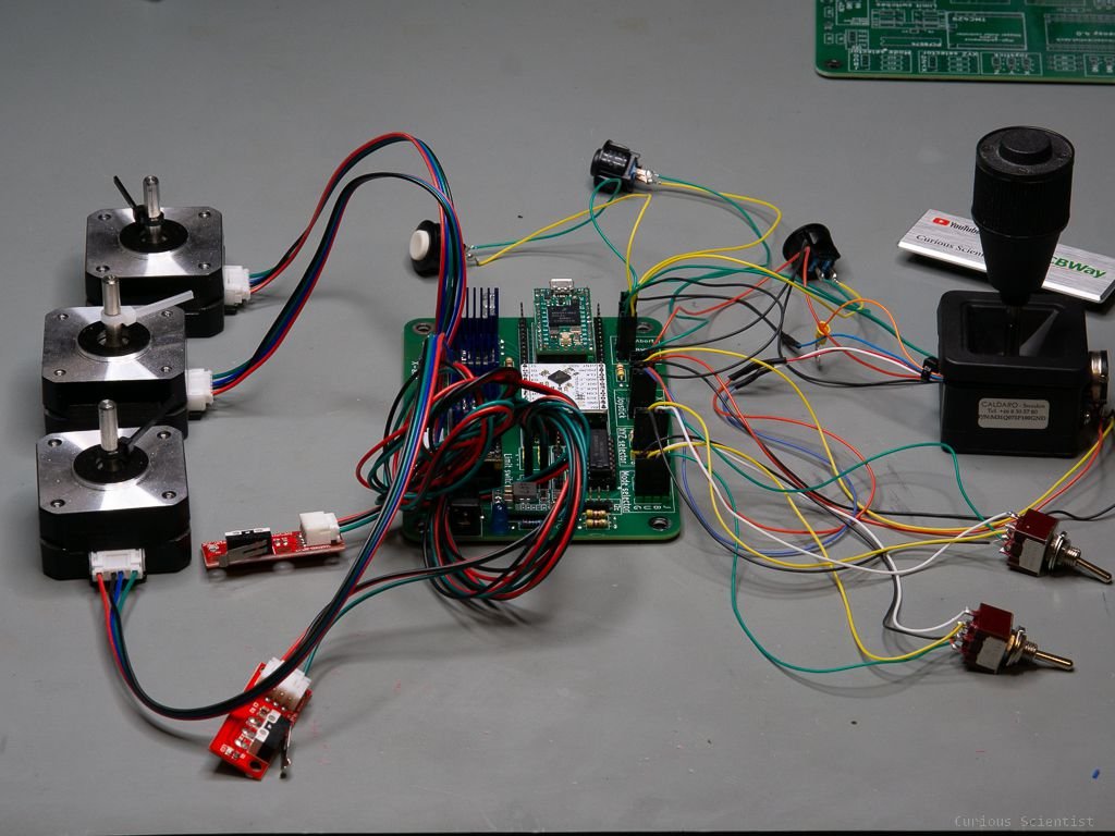
Now that the XY stage is installed, the next step was to connect the cables to my stepper motor control board. While I'm not currently using the limit switches, I plan to incorporate them into the system in a future video, implementing a homing routine at each startup for initialization.
Although the system is responsive to the joystick and buttons, some fine-tuning is still necessary. Specifically, I need to adjust the speed for each axis to prevent stalling and refine the formula that calculates motor speed based on joystick position. However, to avoid making the current video excessively lengthy, I'll address these adjustments in a separate video.
Gallery and resources
Please buy the relevant parts using my affiliate links!
Join my YouTube membership!
Get my PCB from PCBWay!