Stepper motor developing platform
In this video, I show you my newest device which is a stepper motor developing platform. I often work with stepper motors, either because I develop a new project, or because I have a customer that needs a stepper motor-based solution. Usually, I assemble the circuit with all the components on a breadboard. This is sometimes cumbersome, especially if a lot of parts are involved. Too many cables and connections, sometimes different drivers or different components…etc.
So, to solve the headache, I decided to create a PCB where all these components can be embedded and I can develop code for stepper motor projects with great ease.
About the board
The board is a “hybrid” PCB with some SMD components (AS5600 circuitry and the DC-DC converter) and some off-the-shelf parts and modules. I tried to make the board as compact as possible while still providing enough space to comfortably access the controls (buttons and rotary encoder) and the connectors. The SMD parts are 0603 (1608 metric), so with a little skill and patience, one can solder all the components without a stencil. A good way to solder the SMD components manually is to first leave a little solder blob on one of the solder tabs for the component. Then, the component should be placed over its place, on the recently left solder blob. Then, while holding the component in place, the solder blob can be remelted with a soldering iron. This will fix the component in place and then we can proceed with the rest of the legs. If it is a 2-pin component (passive), we can simply heat up the other (unsoldered) pin and then add a tiny bit of solder, to make the connection. If it is an integrated circuit (IC), we can apply a little flux over the pins and then spread a small amount of solder around the IC. The flux will help to make the solder stick to the pins of the component and it will also help to avoid bridging. Alternatively, we can apply a small amount of solder paste around the components or at their solder tabs, and use a heating tool to blow hot air on the area to melt the solder.
The core of the board is an STM32F401CCU6 microcontroller board. This module is a very cheap (about $3-$4), but extremely powerful microcontroller board. It has many GPIO pins and plenty of peripherals that allow a huge degree of freedom when developing circuits with it. For example, the AS5600 encoder uses one of its i2c interfaces, the TMC2209 uses one of its UART interfaces, and the display will use one of its SPI interfaces. Also, thanks to the fact that most of the GPIO pins can be configured as interrupt pins, the buttons, the rotary encoder and the limit switches (LS1, LS2) can all be set up using an interrupt instead of polling. Most importantly, thanks to the STM32Duino framework, we can develop code for the microcontroller using the Arduino IDE. More adventurous people are encouraged to use the STM32CubeIDE platform and learn the HAL (Hardware Abstraction Layer) framework. It gives much more powerful access to the microcontroller and allows us to program it to utilize its full potential.
Another key component of this circuit is the TMC2209 board. This is a novel stepper motor driver board with many great features. It can be controlled with the traditional STEP and DIR pin pair, but it can also be controlled via the UART connection. My example Arduino code demonstrates both options. While the STEP-DIR pins can be controlled using the AccelStepper library, the UART control requires the TMCStepper library.
One of the main specialities of this driver is that it can drive the stepper motor silently (StealthChop feature). This is beneficial, for example, in 3d printers where several stepper motors work simultaneously which can be quite noisy. But in general, it is nice to have silent motors. It also can detect stalling (StallGuard feature) which can be used for homing without limit switches.
Please notice, that there are several driver boards that use the TMC2209 chip. If you are going to replicate my project, it is very important to have the exact same driver. Some drivers have slightly different pin layouts and using a different TMC2209 board could render the developing platform inoperable.
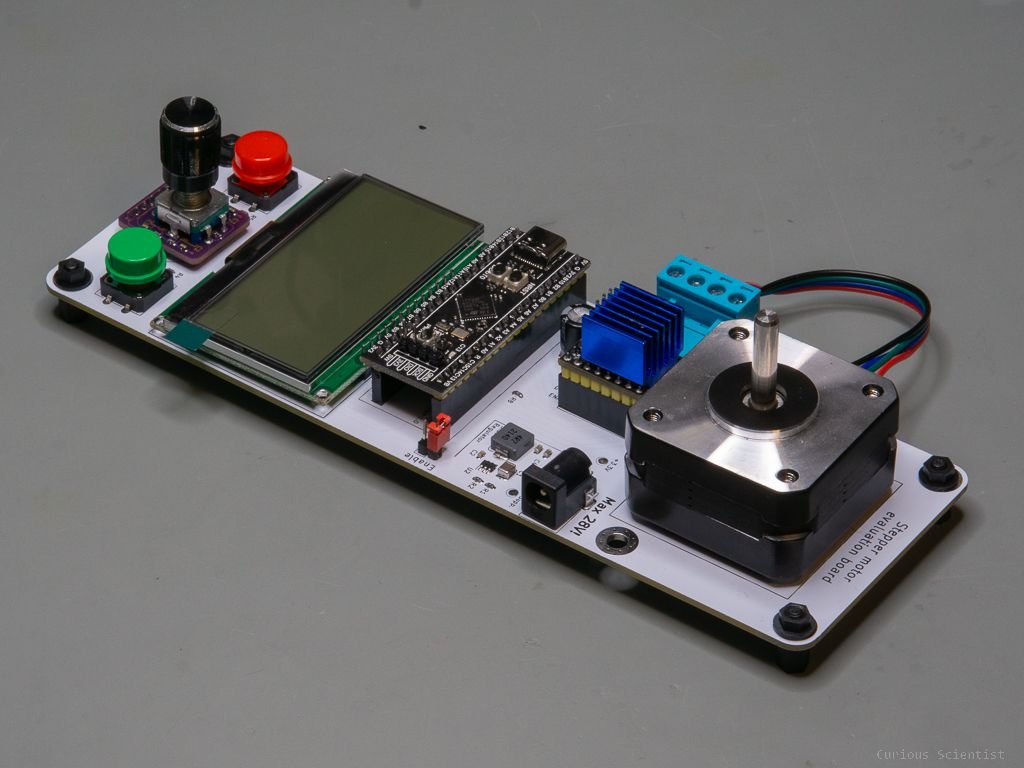
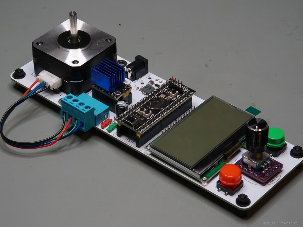
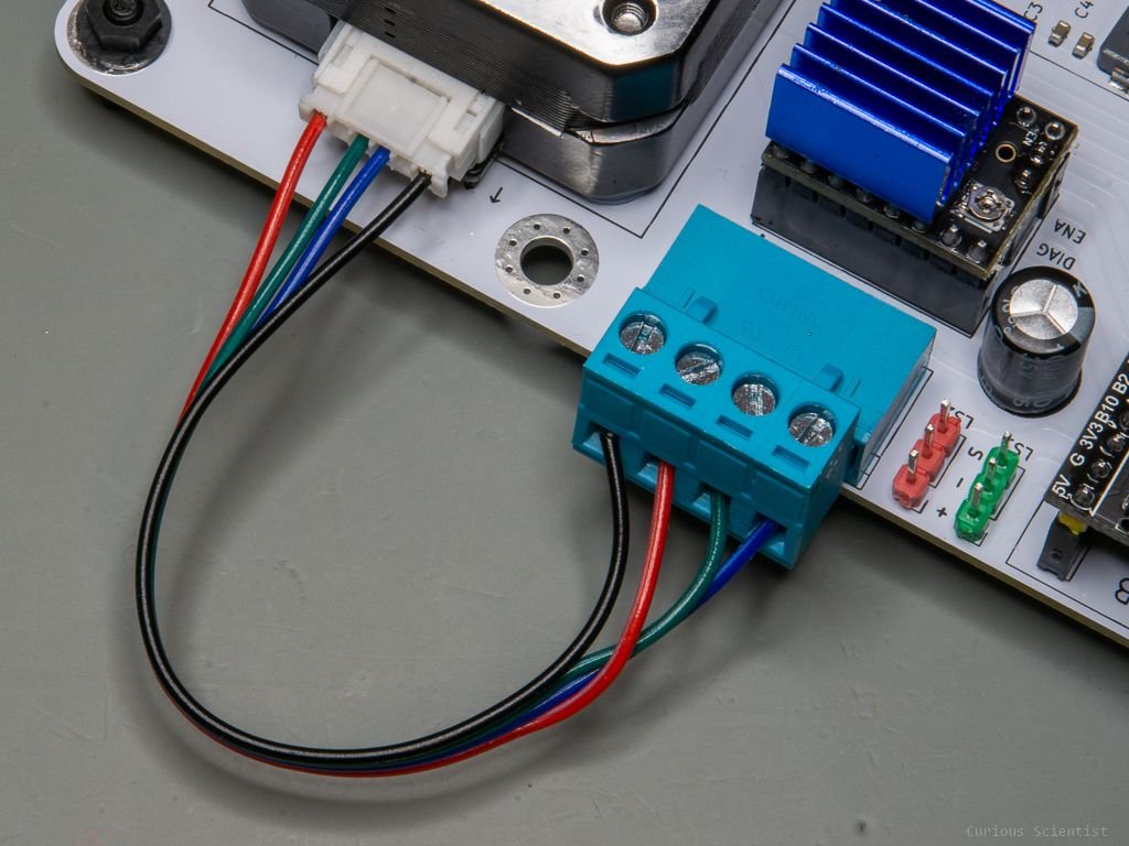
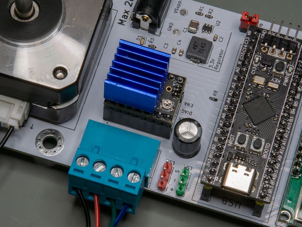
PCB with the STM32F401CCU6 board. One can also see the 3.3 V buck regulator part, the TMC2209 (with a blue heatsink) and the connector for the stepper motor pins.
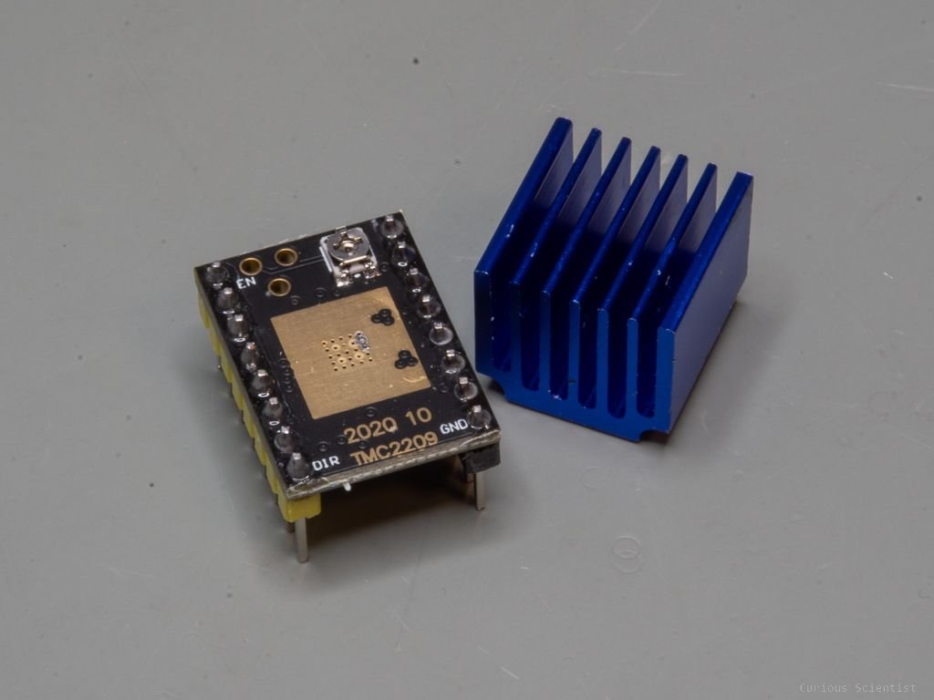
TMC2209 driver used in the developing platform.
Another important feature of the platform is the AS5600 magnetic absolute encoder. I have a relatively popular video and Arduino code for this device. This little device works together with a magnet mounted on the shaft of the stepper motor. When the magnet is rotated, the change in the magnetic field is detected by the AS5600 chip and this change is then converted into a digital value that represents the position of the magnet within the chip’s coordinate system. The chip has a 12-bit resolution which means that the angular resolution is about 0.088° (360/4096). Just as a reminder, a full microstepping produces a 1.8° rotation on the shaft of the stepper motor. The chip can resolve about 20 times smaller steps.
The PCB is designed in such a way that it can accommodate a NEMA17 stepper motor (31 mm x 31 mm hole-to-hole distance with M3 bolts). When the motor is properly mounted and there’s a sufficient gap between the chip and the magnet, the chip will provide precise feedback on the position of the shaft. The purpose of this feature is to be able to practice and study closed-loop control. I know that when a system is set up properly, stepper motors do not need a closed-loop control and the best example of this is the 3d printers that we can buy for peanuts and can maintain submillimeter precision. However, they are still good systems to practice the principles of such systems. So, I still feel the relevance of it.
Other than a closed-loop control we can also simply just use the sensor for feedback. For example, we can check if the stepper motor arrives at the desired position or if it maintains the speed…etc. We can also send it to a target position by relying on the shaft position instead of the number of steps…etc. The possibilities are endless and it is really just up to the imagination of the user.
The power supply is solved in a (I think) neat way. Since the STM32F401CCU6 is mainly 3.3 V-compatible, I designed the rest of the circuit to be 3.3 V-compatible, too. The pull-up resistors for the buttons and the i2C pins and the components are all selected to be able to work with 3.3 V.
First of all, I had to think about the maximum voltage that the TMC2209 driver board can take. This is 28 V in the case of the driver I picked. In fact, some datasheets on the internet state 38 V, but I think it is a typo as all the official Trinamic documents (chip, eval. board) state 28 or 29 V. So I feel better to say 28 V as the maximum voltage.
So, this 28 V directly goes to the driver. Since 28 V is not a typical “commercial” voltage value, I recommend using a 2 A, 24 V power supply, a wall-wart. This input voltage is also directed towards the input of the buck converter that converts it down to 3.3 V. The circuit of the converter is inspired by the SparkFun BabyBuck regulator’s schematics. It is a very simple circuit and it provides up to 2 A current which is more than enough for the circuit.
Then the output of the regulator is connected to the rest of the circuit, to the whole 3.3 V network. This part is actually designed with a simple but (hopefully) smart feature. So, the thing is that it can occur that we want to use the board while programming the microcontroller when it is sitting in the platform. This means that the microcontroller and the rest of the circuit is powered from the USB port. If the circuit were powered by both the USB connection and the onboard regulator, something would be fried sooner or later. Therefore I came up with a simple solution. When the board is supposed to be used in a “standalone mode”, then a jumper must be put on the enable position. This connects the output of the regulator to the rest of the 3.3 V network. Otherwise, if the jumper is removed, the 3.3 V network is not connected to the regulator. In this case, the microcontroller board is supposed to supply the whole 3.3 V network.
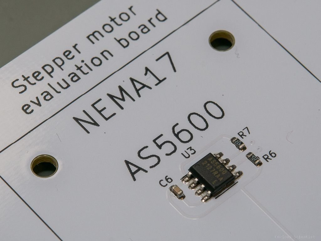
The AS5600 magnetic absolute encoder. It is configured to be used at 3.3 V similarly to the rest of the peripherals.
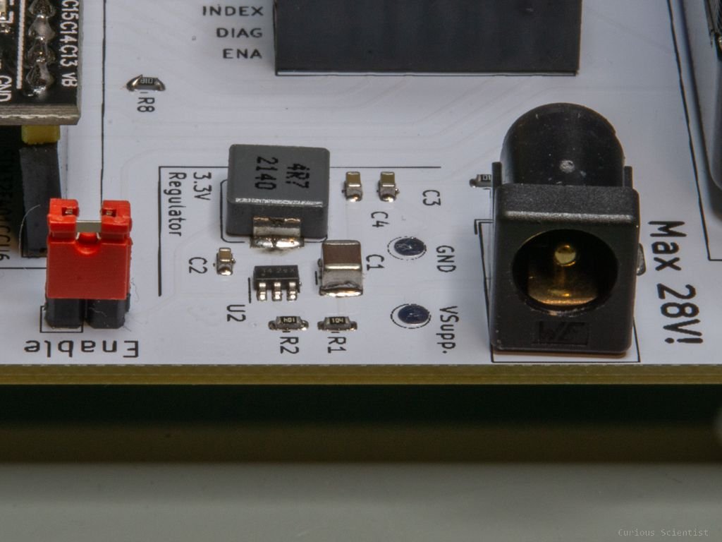
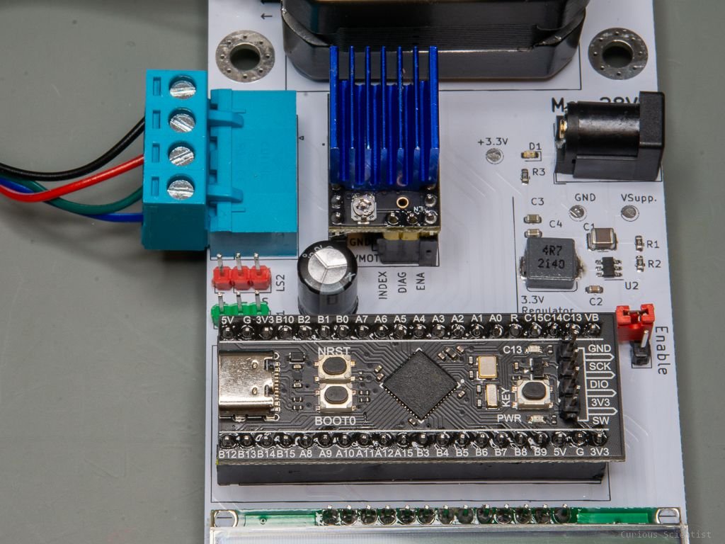
Buck converter section with a 5.5x2.1 mm DC barrel jack terminal. The red jumper pin is used to separate the regulator from the rest of the circuit.
I should also talk about the “inputs and outputs” of the board. The board is equipped with a cheap but good 128x64 pixels graphical LCD. The display has a good contrast, it is easy to read it and its driver chip (ST7565R) is compatible with the u8g2 library which allows us to create a nice GUI. The display uses the SPI interface for communication.
I also added two 12x12 mm push buttons to the circuit. I’ve been using this kind of arrangement in my stepper motor-related circuits for a while and I think it works fine, so I decided to implement it in this circuit as well. The buttons don’t have any specific purpose, it is entirely up to the user how they are used. They can be used as up/down buttons for navigation or changing a value, or they can be used as start/stop buttons…etc. It is really up to the user’s imagination.
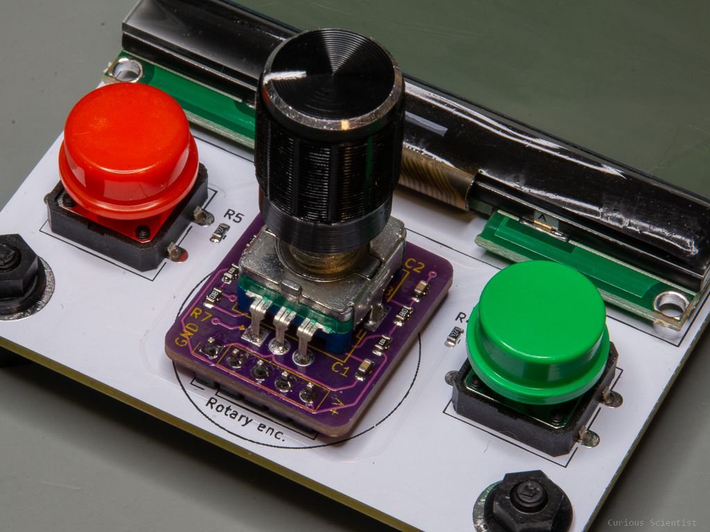
Then, a more important component is maybe the rotary encoder module. The module I used in this platform is actually my very own little design. It is a debounced rotary encoder module. Its advantage is that it uses RC filters and Schmitt trigger circuits to create perfect square wave outputs whenever the encoder shaft is rotated. It may be an overkill, but it is a fun little project. The purpose of the encoder can be also different, depending on the user. I typically use it for navigating in the menu. The rotation can be used to go up/down in the menu, and the switch can be used to enter/exit a menu item. The rotation can also be used to increase/decrease a value (e.g. target distance or speed) or directly rotate the motor. I developed a stepper motor control panel in the past where you can see how a rotary encoder can be used in such an application.
Finally, let’s mention another feature. I equipped the board with two limit switch connectors. Sometimes when I develop code for customers, they require limit switches in their system. Therefore I found it useful to add two limit switch connectors to the board.
One can set up for example a linear rail where there is a limit switch at each end of the rail. They can be used to practice and study homing, or shutting down the motor as a safety feature and so on. Again, the options are endless.
Originally, I had a certain module in mind when I added the connectors. They are simple mechanical switches on a red PCB with 3 cables coming out from the PCB. They are typically equipped with a cable that ends with 3-pin 2.54 mm female socket. I added this specific product to the link collection below.
But actually, as long as you respect the polarity and the pin layout, you can use any switch as a limit switch. You can use an optical gate, or a push button, or even some capacitive or inductive proximity switch as long as they can operate at 3.3 V.

Display and controls. The board has a 128x64 pixels graphical LCD as a display and it has 2 buttons plus a rotary encoder with a switch as controllers and inputs.

Limit switch connectors. The connectors are compatible with the typical mechanical limit switch modules (see below).
Relevant components
Please consider buying the parts using my affiliate links!
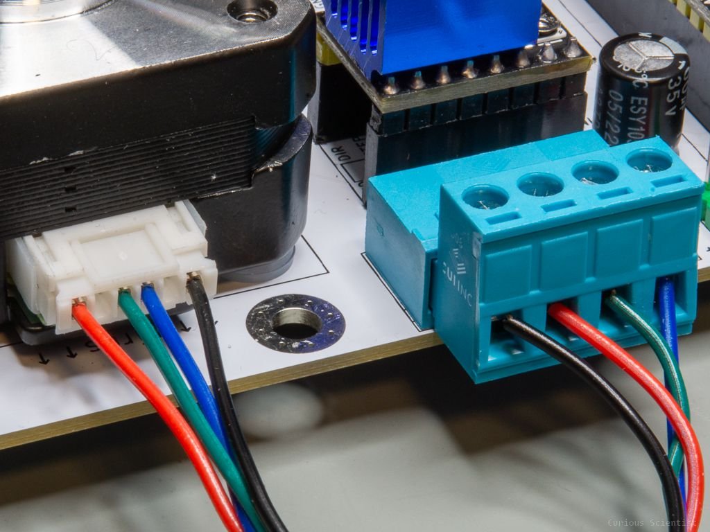
4-pin screw terminal connector
Diametrically magnetized magnet (5 mm)
Join my YouTube membership!
Find the PCB and other resources on my PCBWay project page!