Building a 20x20 cm desktop cloud chamber - Part 2
In the previous video and article, I introduced my newly built 20 cm x 20 cm Peltier cooler-powered cloud chamber. This video and article show you how I fixed the issues discovered in the previous part. This version is a fully working device. It is a relatively simple and easy-to-replicate project. It is ideal for classroom or science fair demonstrations.
Technical details
Most of the technical details are already discussed in the previous article but for the sake of completeness, I write down some details again. These details are also discussed in the video, but I try to add extra information here for those who prefer reading.
Let’s start with the cold plate. Previously, I used the cold plate of an off-the-shelf Peltier cooler refrigeration plate. However, that plate was not exactly 20 cm x 20 cm, it was 18 cm x 21 cm. I wanted to have exactly 20 cm x 20 cm so I could use it with commercial off-the-shelf products that can be used as an enclosure. Several plastic boxes, fish tanks and similar transparent boxes often come in 20 cm x 20 cm or 25 cm x 25 cm sizes which are perfect for this project. But let’s discuss the enclosure later!
Cold plate
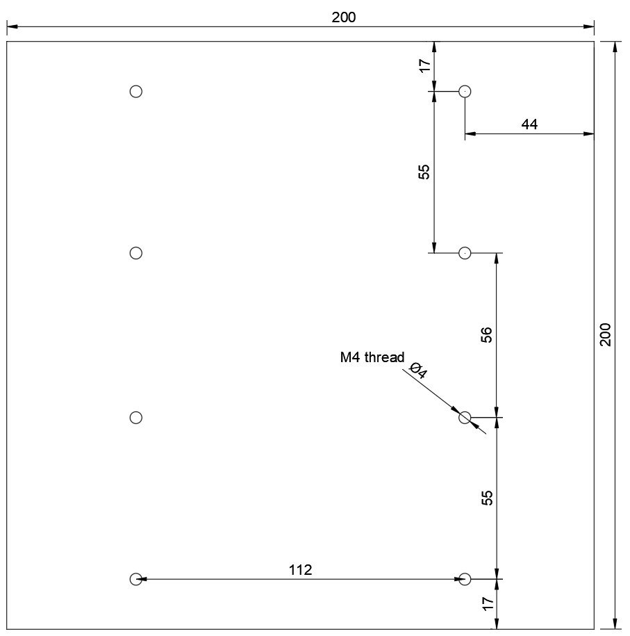
So, first I measured the position of the holes on the previous cold plate. I did not want to change their position too much because I was satisfied with the alignment already. I did a small adjustment, however, just to make everything a bit better arranged. I also drew the board in Fusion 360 just to double-check the dimensions. Then, I marked on the plate where the holes should be and then I drilled M4 threads in the plate. Eight holes in total. I used a hand drill and a special drill bit (combination tap bit) that has a drill bit in the first roughly 1 centimetre, then the rest is the thread cutting tool (tap). This is a very convenient tool because I don’t need to go back and forth between the drill bit and the tap. After drilling each hole, I checked the thread with an M4 bolt. All threads felt good enough. After finishing all 8 holes, I went through both sides of the hole and deburred them with a large drill bit by gently twisting it in the hole. Now the plate is ready to receive the Peltier coolers, the coolers on top of the Peltier coolers, some (optional) thermometer probes and then the insulation.

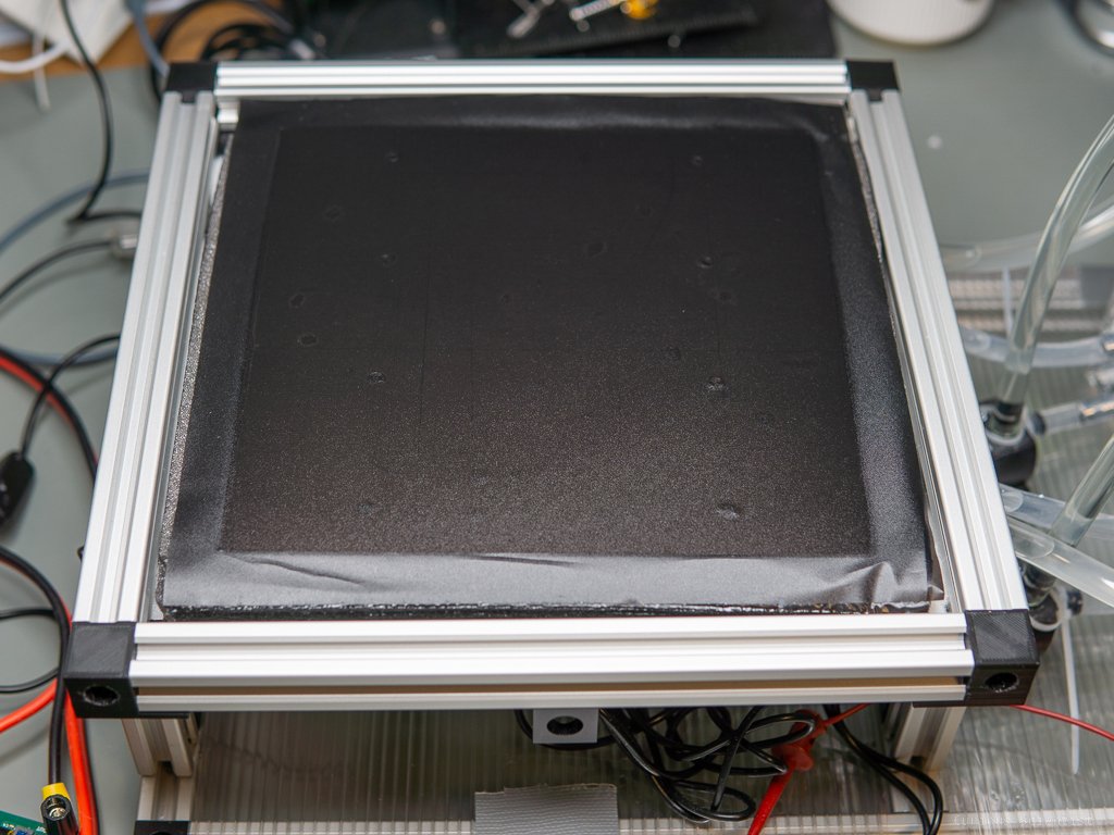
20 cm x 20 cm plate with all the 8 mounting holes.

M4 combination tap bit with one of the threaded holes.
Peltier coolers
The Peltier coolers stayed the same as in the previous experiment, I still use the TEC2-19006 coolers. These are excellent cascade coolers. Due to the fact that it comes in an already sandwiched condition, it only needs a single power supply. This can save a lot of headaches as compared to the “manually stacked” Peltier coolers where two power supplies are needed due to the different required operating voltages (and thus current).
The advantage of stacking is that the maximum achievable temperature difference (dT) between the hot side and the cold side of the Peltier cooler stack is increased. While a regular Peltier cooler can reach around -25°C, this unit can go down to -35°C with the exact same cooling conditions. In an earlier article I already discussed this in more detail and compared the cooler against a regular TEC1-12706 unit.
With cascading, there’s typically a tradeoff in cooling performance. It is always the cooling power of the bottom unit that determines the maximum transferrable heat. However, in the case of the TEC2-19006, I don’t exactly know how the cooling power works because there’s no publicly available datasheet for the device. It claims to have 36 W of maximum cooling power, but without the datasheet and the performance chart, it is difficult to conclude more about this cooler. But it works as I want it to work, so I just accept it.

TEC2-19006 on the cold plate. The bottom left corner is cracked but it is still operable.
Insulation
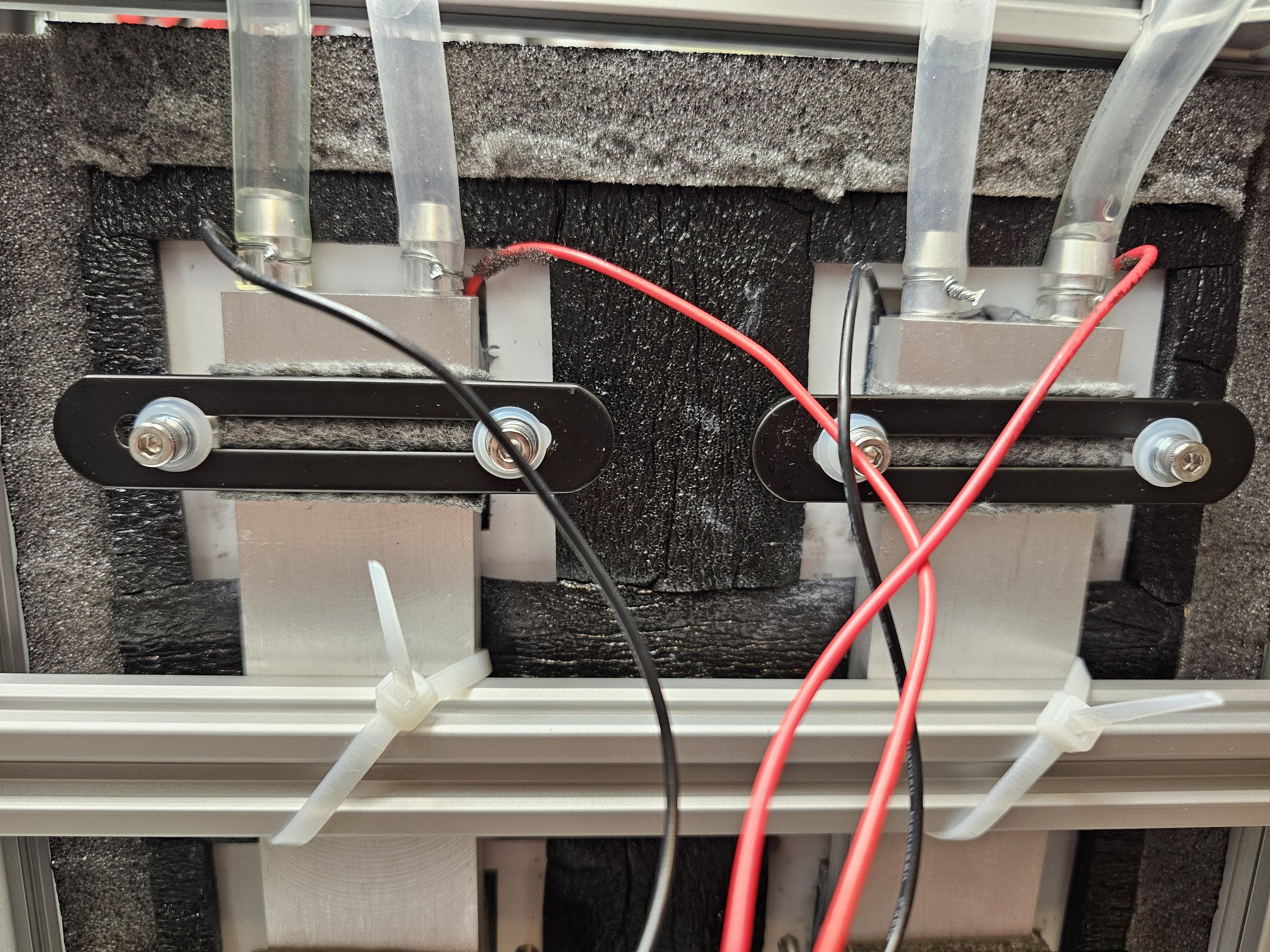
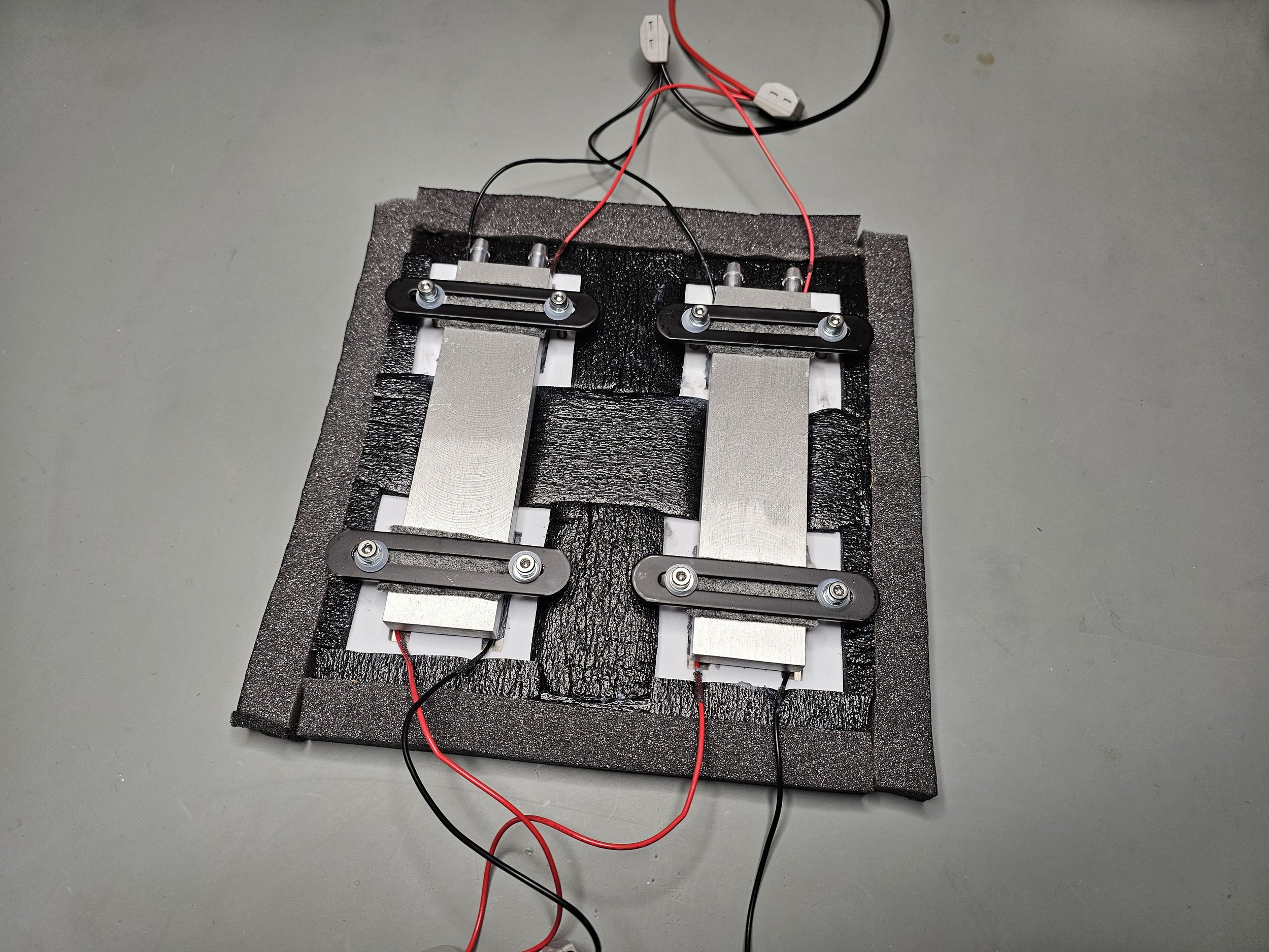
Now, as the plate is complete it is time to attach the Peltier coolers and their coolers, too. I purchased a somewhat better thermal grease to ensure good heat transfer. Then, I decided to go for water cooling this time. So, each pair of Peltier coolers has a 160 mm x 40 mm aluminium water cooling block. I mounted them the same way as I previously mounted the heatpipe-based CPU coolers. I used a bracket to clamp the coolers down. I added a piece of felt between the clamp and the water cooling block to suppress heat transfer and I also added some nylon washers under the head of each bolt to further decrease the heat transfer towards the cold plate (since the bolts are bolted into the cold plate). Luckily, the bolts are stainless steel bolts and they are already bad thermal conductors. But the more heat I can keep away from the cold plate, the better!
Once I finalized the positions of the Peltier coolers, it was time to install the insulation. The insulation consists of several different pieces. First, I used a self-adhesive foam insulation specifically designed for Peltier coolers. Its size and shape exactly match the Peltier cooler. Since it is made to fit the 40 mm x 40 mm Peltier coolers and the holes on it are also aligned with the holes I made on the cold plate, they also helped align everything properly.
Then, I added a 20 mm thick adhesive insulating foam. One side of this foam has a self-adhesive layer, making it easy to attach to any surface. But I must say that it is also a nightmare to cut it because the glue gets stuck in the scissors.
With these two insulations, I fully covered the back side of the 20 cm X 20 cm aluminium plate. However, the fish tank I use as the chamber is 25 cm X 25 cm. So, to make up for this difference, I added a “skirt” to the cooling plate and glued strips of this self-adhesive foam to the side of the plate and the side of the foam glued on the back of the plate. This is good because the plate is well-isolated and insulated from everything, there is no direct contact between the cold surface and any other components of the cloud chamber.
Then, the second layer of the insulation of the cold plate is roughly 10 mm thick (depending on how much I compressed it) polyester wadding. This material is also used in winter jackets or plush toys. I wanted to add an extra layer of insulation to make sure that the back of the cold plate does not really “leak” too much cooling. It also helped with heat leakage around the skirt. Obviously, I could not cut the skirt perfectly, so some parts did not touch the inner wall of the chamber. This polyester insulation helps to fill in those gaps.
Once the insulation was added, I covered the top side of the aluminium plate too. In the previous version, I painted it with spray paint. This was a silly idea because I used isopropyl alcohol in the chamber, which happens to be a good solvent. So this time, I came up with a seemingly better idea. I bought black foil used on the car's headlights to make them darker. It is matte, which provides a perfect background for the traces in the cloud chamber. I cut it to a roughly 25 cm X 25 cm size, so the foil also supports the “skirt” part I made from the foam.
The cold plate is mounted on the frame I made in a very simple way - using zip ties. I found it quick and easy to clamp the cold plate on the frame of the instrument by the two aluminium water cooling blocks. It is easy to install and remove.

Cold plate sitting in its frame. Pipes and cables are installed, but the second layer of insulation is not yet added.

Cold plate sitting in its frame. The white material is a polyester wadding typically used in plush toys and winter jackets.
Water cooling
Once the plate was done, I built a simple frame out of some 2020 aluminium profiles to hold the whole system. It is designed to accommodate everything: the power supply, the cold plate, the chamber, the water cooling. To make things easier, I attached the cold plate to the frame using some zip ties. It is easy to remove it and it is easy to redo it. Once the plate was aligned properly, measured some silicone hoses and attached them to the water cooling blocks. To make sure that they don’t leak at the fittings, I clamped them down with some steel wires.
Once the pipes were in place, I added a plastic plate to the frame. This plate supports the water-cooling parts. Later on (not shown in the video), I also added another plastic plate under to the frame under the cold plate. This plastic plate holds the power supply, the DC-DC converters, the power meters and other electrical devices.
The water cooling is a relatively simple system. Each Peltier cooler pair (or aluminium block) has a 240 mm radiator. They are cooled by two Arctic Cooling P12 MAX fans. Very good fans with high static pressure and good airflow. The water circulation is maintained by 2 submersible pumps. However, they are not submersed, they sit on the top of the plastic plate. The water is stored in two acrylic water tanks (1 for each side). The whole loop looks like this: The water is sucked out from the water reservoir through the bottom fitting, then it is pumped up to the inlet of the radiator. Then, the water exits the radiator and goes into the aluminium water cooling block to cool down the hot side of the Peltier coolers. Then, the water exits the cooling block and goes back to the water tank through the fitting on the top.

Acrylic water reservoirs. Each cooling block has its own pump, water tank and radiator.

240 mm radiators with the Arctic Cooling P12 Max fans.
Electronics
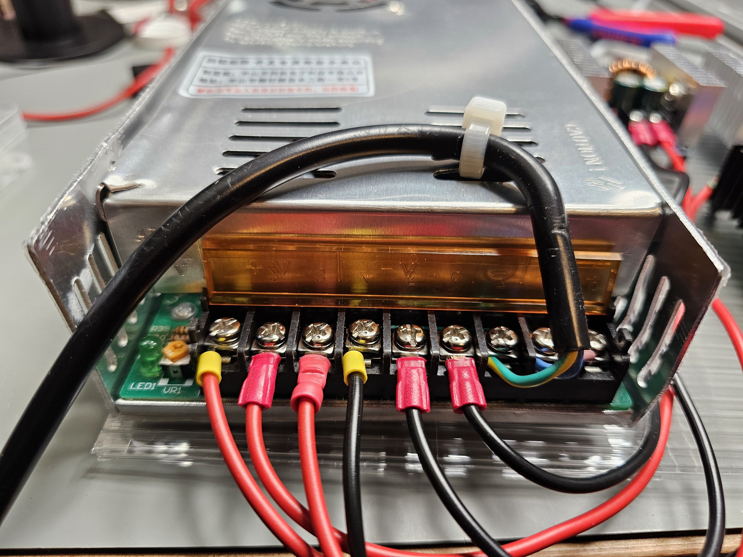
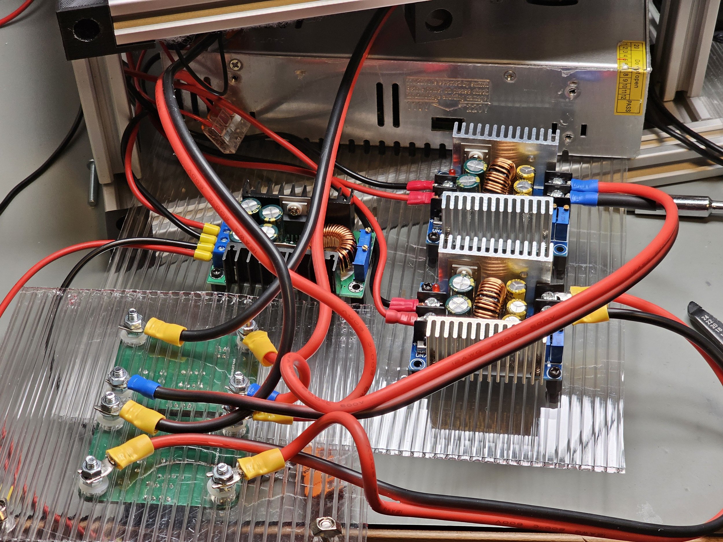
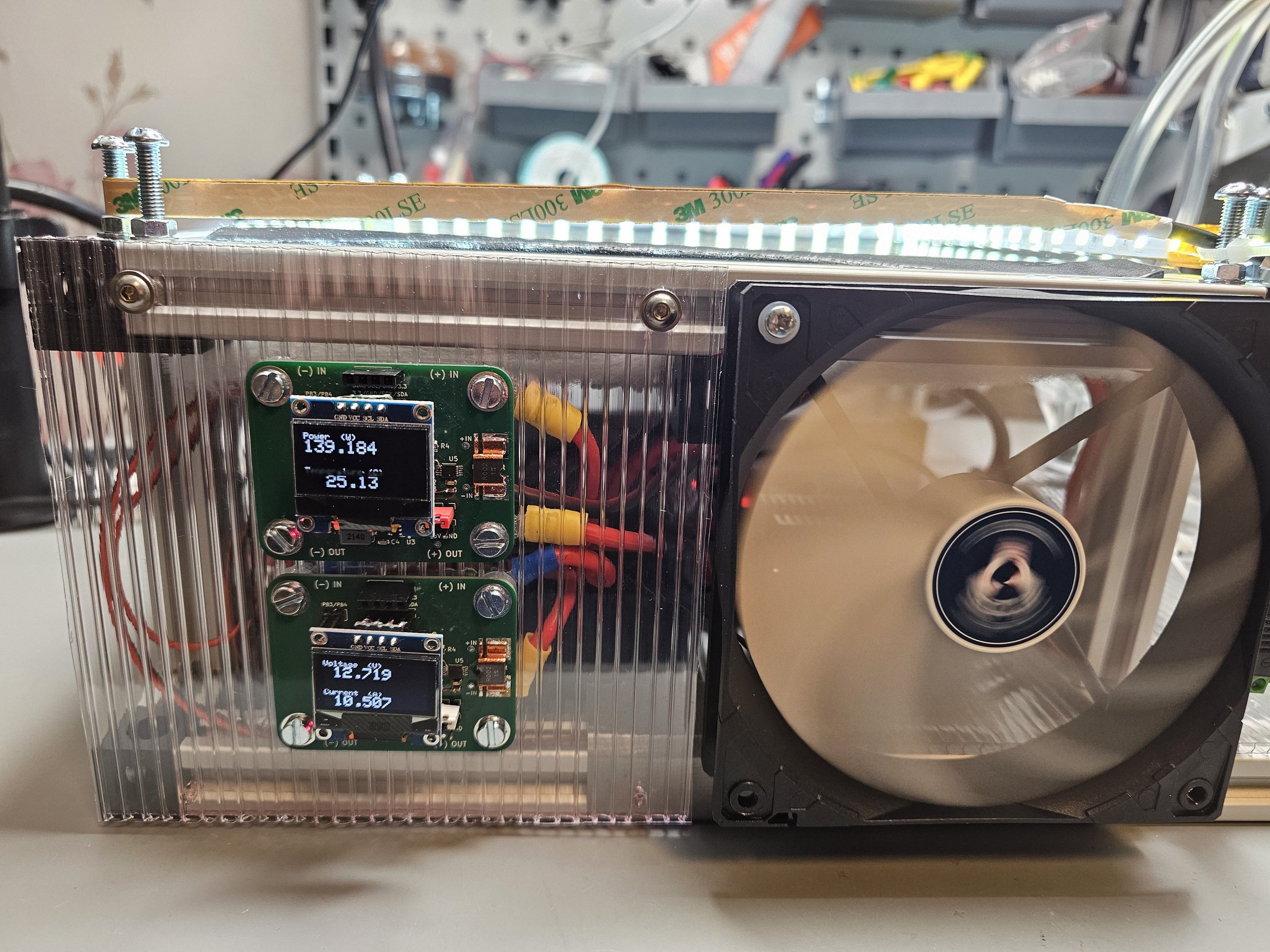
The electrical system stayed basically unchanged. I still power the whole thing with a 24 V 16.7 A (400 W) switching power supply. The output of the PSU is split into three rails, two rails go into a SZBK07 300 W DC-DC buck converter to allow power regulation for the Peltier coolers. Each DC-DC converter drives 2 Peltier coolers connected to it through my custom-made DC power meter in parallel. I added the power meters because I could easily adjust the power for the Peltier coolers and I did not need to struggle with the multimeter. In addition to the two SZBK07 DC-DC converters a third XL4016 DC-DC converter is also added to the circuit which drives the LED strip that illuminates the vapour, the 2 pumps that circulate the water in the cooling loop, and the 4 fans that push air through the radiators. These 3 device groups take up an additional ~2.66 amps from the power supply. Thus, I used a smaller DC-DC converter. The total wattage consumed is around 305 Watts which is about 76% of the total available power. The 400 W power supply, even if it is a bad quality one, should have enough reserve to provide 305 W. And it seems to have enough juice because it did not melt down even after running for several hours without interruption.

Power distribution. The bottom DC-DC converter provides power for the auxiliary devices such as the pumps and fans and the LED strip and the top two DC-DC converters provide power for the Peltier coolers (1 converter serves 2 Peltier coolers).

Schematics of the power distribution
Operation
One of the most critical things is the isopropyl alcohol. The system has to have enough of it, so enough vapour can be produced. I cut two strips of felt that almost covered the whole 25 cm x 25 cm area of the top of the chamber. I attached the felts to the top using magnets, then soaked them with roughly 30-40 ml IPA. In the beginning, I used much less alcohol and even though the cold plate was cold enough (-27°C or sometimes even lower), I could not see any clouds forming because there was not enough vapour. Even more could be added, especially if you want to run the system for a longer time. However, keep in mind that once the alcohol has condensed, it accumulates on the surface of the cold plate. After a while, the surface can form puddles and eventually, the alcohol will start to leak if it finds its way out of the chamber. One can build a recirculation system for the alcohol, but I found it unnecessary because even after 1 hour, the alcohol stayed inside the chamber.
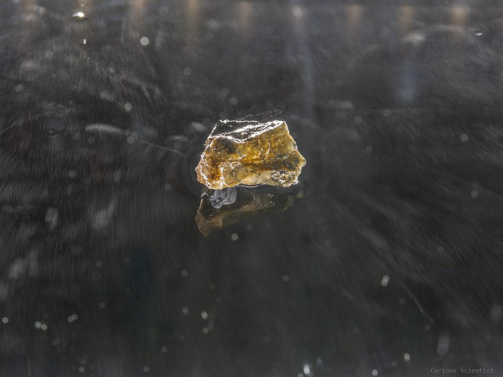
Then I put a radioactive mineral, allanite, in the middle of the cold plate, placed the chamber in its place and then started up the system. In less than 10 minutes, the system was up and running and a remarkable amount of traces were visible. An interesting thing is that if I am around the cloud chamber, then the traces are nice and visible. However, if I do not actively observe the system but record it with a camera and leave the room, the traces almost entirely disappear. Kind of like Schrödinger’s cloud chamber. :) And after a little experimenting, I found out the explanation and luckily it is simpler than quantum mechanics. It seems like when I am moving around, there is some static electricity generated which creates an electric field and this interacts with the whole chamber. I tried rubbing a microfibre cloth and then put it close to the chamber and I immediately saw the traces popping up. So, it has to be something with static electricity and an electric field. More professional cloud chambers use a high-voltage grid to influence the charged particles in the chamber, so I basically did something similar. I must find a way to maintain a high-voltage electrical field to produce spectacular traces. Probably a simple Van de Graaff generator-like contraption would be sufficient. I will find something to create a high-voltage field inside the chamber and report back the results.
Some extra resources and pictures
Please consider using my affiliate links to purchase the relevant products!
TEC2-19006 Cascade Peltier cooler
Peltier cooler insulation foam
400 W, 24 V, 16.7 A DC power supply
12 V, 6 W submersible water pump
Self-adhesive insulating foam strips
Join my YouTube membership!