DWIN Displays - Sending and receiving numbers
In this video, I will show you how to send and receive numbers with a DWIN display. I will show both integers and floating-point numbers. I think the floating point number section of this tutorial is particularly important because none of the tutorials I saw on this display showed how to do it. So, I will attempt to explain it properly in my material.
I already made two videos on this display. For basics, please check my first review article and video, and for sending and receiving text, check my other article.
Sending integers and floating point numbers between a DWIN display and an Arduino
Before moving forward, make sure that you checked my introductory article on this display. I will skip those parts here that I explained there.
I assume that you already know how to:
Generate a font file
Generate the 32.ICL file with the pages
Generate the T5LCFG.CFG file with the configuration parameters
Upload the files (content of DWIN_SET folder) to the display using an SD card
Step 1 - Drawing the displays
I created two pages, a main page and a keypad page. The main page has a field for a received integer number and a field for a floating point number. These fields are Data Variable displays and they can be found under the Text Show menu at the top of the program.
Furthermore, it also has a button that opens up the keypad (page 2) and it has a text field where the values we entered on the keypad will appear. The keypad button is an ASCII Text Input button from the Touch Control menu, and the text field is a Text Display item from the Text Show menu.
The keypad has 0-9 numbers, a decimal point and a minus sign button, as well as a backspace (clear) and an enter button. Once Enter is pressed on the keypad, the display returns to the main page and the value appears in the field at the bottom of the display.
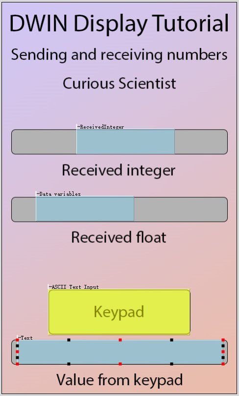
Main page with 4 active fields.

Keypad page with the assigned buttons. The typed numbers will appear in the white textbox at the top.
Step 2 - Assigning parameters to the fields
First, we start with the integer. I assigned the following parameters:
VP Address: 1000
Font size 36
Variable type: Int (2 bytes)
Integer digits: 4
A two-byte integer can store a number between -32767 and +32767. If you know that you will fall out of this range, use a four-byte integer. It can store numbers between -2147483648 to +2147483647.
Then, I used the following parameters for the received float:
VP Address: 1100
Font size 36
Variable type: float (4 bytes)
Integer digits 4 (number of digits on the left side of the decimal point)
Decimal digits 4 (number of digits on the right side of the decimal point)
Now we jump to the text field. It is set up in the same way as in my previous tutorial, so I don’t go into deep details about the nuances:
VP address: 2000
Encoding mode: 0x02=GBK
Text length: 100 (bytes)
X and Y direction lattice number: 48
Finally, we look at the keypad parameters:
Data auto-uploading is checked
VP address: 2000
it is shared with the text field, that’s how the text field will see the entered data from the keypad
Text length: 50 (words)
Input mode: Re-input (any time the keypad is opened, we start with new a new number)
Font width and height: 48
Display mode: direct display
Keyboard location: Other pages
Please check my video if you are unsure about the Input display area, Keyboard setting and show location parameters. It is easier to see how it works in a video.

Parameters I used for the integer

Parameters I used for the float
Step 3 - Setting up the keypad

I opened the page that contains the keypad in the Touch and display config tab and added a Basic Touch Module over each keys. Then looked up the key value(0x) section for each key. To assign the numbers, symbols and functions, you must click the Full QWER keyboard checkbox first. Then the Set button appears. Click it and then on the pop-up window select the letter that you want to assign to the touch module. You have to do this for all the keys.
Once this is done, you can test the keypad in the DGUS software. Go to Display at the top and click Preview from first page. Click the icon and virtual screen with the simulated display will appear. Some characters will be incorrect, but neglect it. The virtual screen has a few bugs. Click on your keypad button as you would touch the display and then test the functionalities by entering some values. If you did everything correctly, you should see the entered number at the bottom of the display.
Step 4 - Setting up the sending and receiving code on Arduino
I explain the Arduino code step-by-step in my video, so please make sure that you check my video. If you want to have my code in a downloadable format, please consider supporting me on YouTube memberships.

Buy DWIN displays using my affiliate link to support my work!