DWIN Displays - Sending and receiving text with Arduino
In this video, I show you how to send and receive text using an Arduino and a DWIN display. Sending an text to the DWIN display and showing it is relatively simple, however to enter text on the display and then sending it to the Arduino is a bit more complicated. I show all the small things that you need to take care of to successfully perform these tasks. Below there is a video with all the instructions, but if you prefer reading an article step by step, please keep scrolling. I wrote a detailed set of instructions under the video.
Sending text between a DWIN display and an Arduino
First, before starting with the work, please make sure that you watch my introductory video on these displays and read my article. In the following chapters, I will assume that you have read my introduction and know the basics about how to prepare the config files and how to upload them on the display.
For this tutorial, I was using the DGUS_V7642 version. Please make sure that you use the same version or better. You can always fetch the most recent version of the DGUS toolkit on DWIN’s webpage.
Step 1 - Generate the fonts:
First we need to create a font package. When you open the DGUS toolkit, you will see a section at the bottom of the window which is called DGUS config tool. Within this section, there is a label called 0# word bank generating. Click on it, then select and adjust the font so all the displayed fonts are visible.

DGUS config tool section - Here you can reach most of the important tools for generating different config files for the display
Keep changing the scale and shift values to fit the letters in their frames properly. It is a good idea to choose a wide font like G, M or W because if they fit, the rest of the letters will fit too. When satisfied, click on the Create_0DWINASC.HZK button. After the process is finished, you can find the file in the same folder as the executable file of the DGUS toolkit. At this point, it is a good idea to create a folder called DWIN_SET somewhere and copy this file there. Later, you will copy the whole DWIN_SET folder on the root folder of an SD card.
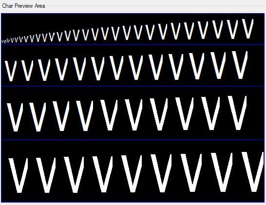
Sample letter with wrong scaling parameters

Sample letter with correct scaling parameters
Step 2 - Create the config file:
While you are still looking at the DGUS config tool area, you can see a label called Config generator. Open it and you will see a bunch of options. There is one very important function which is not really emphasized in the documentation of the DWIN displays and if you miss it, you won’t receive any data from the display. There is a field called Touch-sensitive Variable Changes Update. By default, this is set to Non-auto, but actually, it should be Auto. If it is Non-auto, the display won’t send any data to the serial port even if you check the “Data auto-uploading” option where you modify the parameters of the input field of the display. Another very important parameter is the Baud Rate. It is 115200 by default, but I have noticed that Arduino’s software serial library does not like this value. So change it to 9600. Here, you can also turn off the touch sound, adjust the rotation of the display and so on. When you changed all the values, click on New CFG and save the file in your DWIN_SET folder as "T5LCFG.CFG”.

Config generator. The most important parameter is the Touch-sensitive Variable Changes Update. It should be Auto. Also, don’t forget about the 9600 Baud Rate.
Step 3 - Drawing the display and generating the page files:
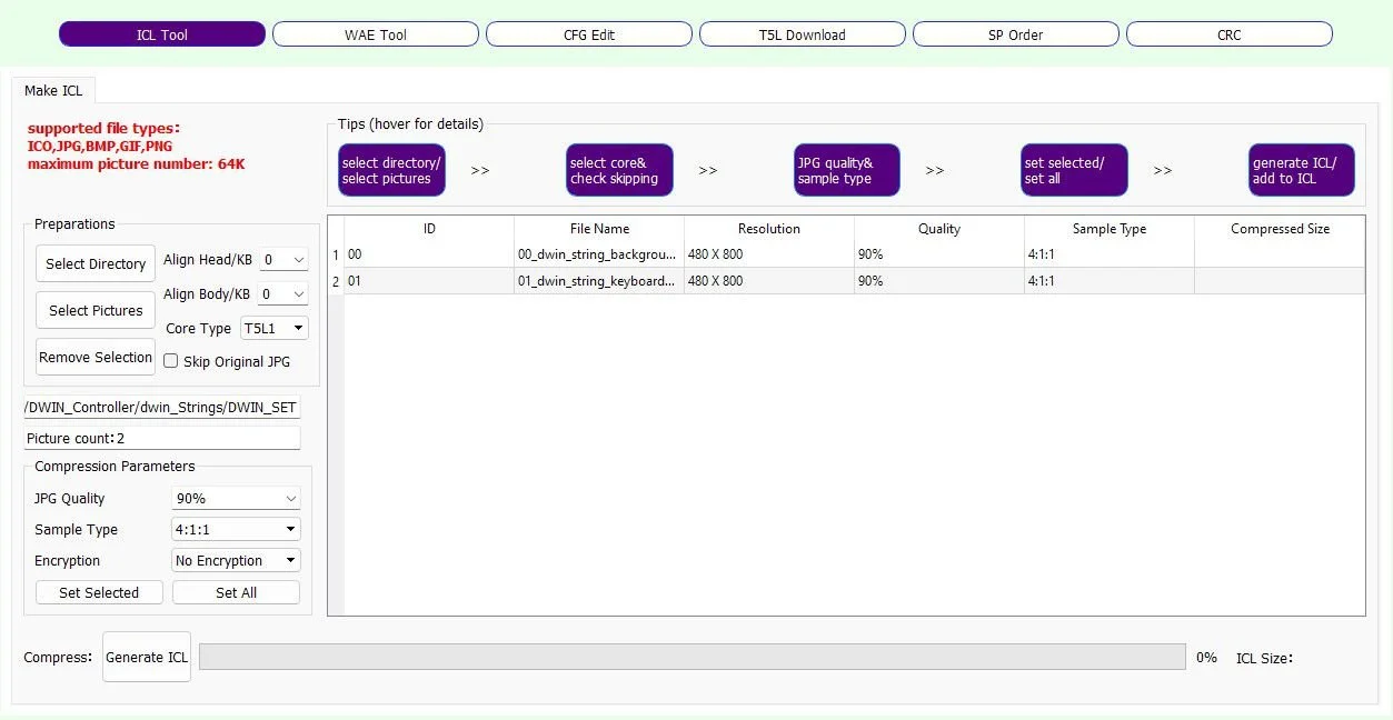
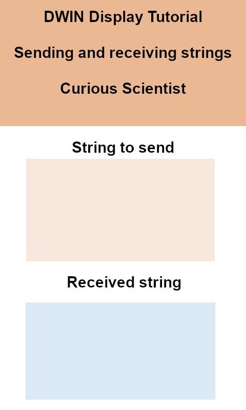
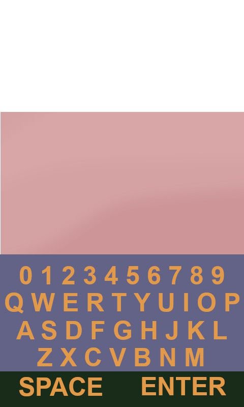
In this step first, you have to draw your display. Open your favourite image editor and create the display with areas, fixed text and so on. You also have to draw your own keyboard. Make sure that you have the same orientation and resolution set for the images as your display’s values. Save the pictures as jpeg files and make sure you add “00” in front of the first picture’s file name, “01” in front of the second picture’s file name… and so on. Then go back to the DGUS toolkit and find DWIN ICL generator at the bottom of the display on the Welcome panel. Click on the Select Pictures button and load the pictures. Click Generate ICL and save the file as “32.ICL”. Place the file in the DWIN_SET folder.
Now navigate to the Touch and display config (main display) and on the left panel called Images view click the + (plus) button and load the same images (jpeg files) that you just packaged into the ICL file. These are the pages that we will work with from now on.
Step 4 - Adding keyboard controls to the display
First, I want to show you how to create the keyboard. So, let’s open the keyboard’s picture from the Images View list. As you can see in my picture, the image is packed with yellow rectangles over each character. Yes, you suspected correctly. We have to add each button one by one. :)
At the top of the main window, go to Touch Control, then click on Basic Touch Control. Once you clicked, you can draw a rectangle over a letter. This essentially means that this yellow rectangle will become an area on the display which is sensitive to touch. Through this module, we can program the display how it should behave when we touch the area. In this case, it will send a character to the serial terminal that corresponds to the letter which is covered by the yellow rectangle.
Once you have the yellow rectangle over your letter look at the right panel of the DGUS toolkit and find the key value (0x) section. Click on the “Full QWER keyboard” box, then click on the Set button that appeared.
A larger window will pop up with all the values that you can assign to the yellow rectangle. Select the corresponding letter or number, the window will disappear when you click the number, then the corresponding key value will be shown in the text box. For example, if you pick the letter “t”, 5474 will show up. Now you just need to repeat these steps about 40 times…
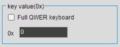
This part assigns a key value (i.e. a letter) to the touch area

Here you can select the keycode for the touch area
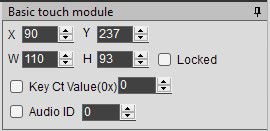
Good advice: Draw only one rectangle first. Then go to the section where you can modify its size (top right corner of the software’s window). Adjust the width (W) and height (H) using the numbers until you are satisfied with the yellow rectangle’s size. Then you can duplicate it using CTRL-C → CTRL-V. This way you don’t need to struggle with sizing them equally.

Keyboard page with all the characters with their own individual basic touch modules and assigned parameters
After assigning all the values to the keyboard, navigate back to the main display. We continue working on the keyboard functionality. Navigate to the Touch Control on the top of the display and click ASCII Text Input. Select an area that should show the keyboard when you touch it. In my case that is the “salmon-coloured” rectangle under the “String to send” text (see earlier images of the pages).
Then, we have to set it up using the parameters on the right-hand side panel.
Check the “Data auto-uploading” text box, so the keyboard will pass the values to the serial port.
Set the VP address to 1000. This is the start address where the data is stored.
Set the text length according to your requirements. I set it to 50. Also, don't forget that the unit of the value is a word (2 bytes)
Set input mode as re-input (opening the keyboard again starts with empty text)
Set the width to 24 and height to 48
Set the keyboard location to “Other pages” - This will open the keyboard page when you touch the area
Click on the Keyboard Setting button, then select the page where you store the image of the keyboard. Here, select the area of the keyboard together with the area (typically above) where the typed text should appear. Press OK when you are satisfied. Then click on the Set button next to the “Show location” text boxes. This is the point where the previously selected keyboard area’s top left corner will be placed. If you leave it at (0,0) the keyboard area will show up starting at the top left corner of the main page. I did it like that.
Now go to the “Input display area” and click the Set button. This option will determine where the typed text will be shown when you open the keyboard. When the pop-up window is shown, select the “Displayed Keyboard” box at the bottom (see the picture to the right). Then select the area above the keyboard. The typed text will show up there while typing.
We are basically done with the keyboard. You can play around with the font size and other parameters I did not mention here.
Now we need a text box that “catches” and shows the text we typed on the keyboard. Go to the Text Show at the top menu and select “Text Display” (The software has a typo, saying “text dispaly”). Select the area over the rectangle where we placed the ASCII text input field. Then follow these steps:
Set VP address to 1000, or anything, which is the same as the VP Address of your ASCII text input field. They share the same memory area and this is how the text box will be able to show the text from the keyboard
Set encoding mode to 0x02=GBK
Set text length to 200. Contrary to the keyboard, the text length is stored in byte units here. So, ideally, you need 2x the value that you set for the keyboard.
Set font size, for example, X and Y direction lattice number 24.
Now you can save the project and click generate. Then go to Display and click “Preview from first page”. Click on the area where you placed the keyboard and type in something, then press enter. If the text you typed shows up in the text box on the main screen, you did everything well. Now take all the files from the DWIN_SET folder, and copy them onto an SD Card. If you don’t know how to proceed, check my previous tutorial where I explained it carefully.
Once the files are uploaded, connect the display via DWIN’s serial adapter. Now, open your favourite serial terminal software and connect to the display. Now touch the display in the keyboard area and type something. As you can see, I also typed in something. Let’s see the data format to understand the values better. This is crucial because this is the basis for building the Arduino code.
5A A5 10 83 10 00 06 73 6F 6D 65 74 68 69 6E 67 FF FF 74
5A A5: header
10: total data length in bytes: 0x10 HEX = 16DEC
VP read command (1) + VP address (2) + Text length in words (1) + Text length (12) = 16
83: VP read command
10 00: VP read address
06: Length of the received data in words (2 bytes = 1 word)
73 6F 6D 65 74 68 69 6E 67: “something” in HEX
Based on the above data it is relatively simple to set up a rule for grabbing useful data. The structure of the output data from the DWIN display is always the same. So, essentially we just monitor the serial connection with the display, save each message in a char array, then if the 3rd byte (0-indexed, so the “item number 4” which is the “83” in the above sequence) is equal to 83, then we start extracting the data from the 7th byte ("73” in the above sequence) which is the first value of the string we typed on the display. Since the text is terminated by “0xFFFF”, we just keep reading until we see “0xFF”. As you can see in the video, it works just fine.

This is what is shown when you click the Set button next to the Input display area. You should select only the pink area in this window.

I typed something on the DWIN display and it appeared on the serial terminal of my PC.
Step 5 - Adding controls to the display to show received data
Now we can send data to the serial terminal directly to our computer or to a microcontroller. We now have to do it the other way too, we need to be able to send data to the DWIN display.
Let’s go back to the “Touch and display config” screen and add another “Text display” over the box under the received string text. Then do the following steps:
Set VP Address to 2000, or something that you want to use, but keep in mind that you already occupied some addresses with the ASCII keyboard!
Set Encoding mode to 0x02=GBK
Set text length to 100 (Unit is bytes)
Set X and Y direction lattice numbers to something like 24 and 48.
Enter a few characters in the “Initial value” text box.
Now you can save the file, generate the code and upload all the files via SD card again. By knowing how the header works, we can send a message to the display manually using the serial port.
The Arduino coding is explained in the video and the code is available for my supporters on Patreon.
Join my YouTube membership!

Buy DWIN displays using my affiliate link to support my work!