DWIN displays and their programming
In this article, I will show you how to communicate with a DWIN display using the serial port of a computer. I got the privilege to receive two displays from the manufacturer for a review in exchange for content made about them. I accepted their offer because I have been always interested in human-machine interfaces (HMI) and I could see that I can use their displays in many of my upcoming projects as well as I can upgrade some of my older projects using the displays.
So, finally, after climbing the steep learning curve, the content is ready for consumption. If you better like listening to the instructions, I made a video with similar content as you can see below.
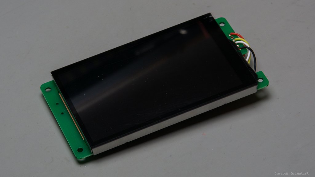
The displays and accessories
Join my YouTube membership!


If you have any inquiries about the screens or want to get a free sample, you can contact them on social platforms like WhatsApp or Email details are given below.
Whatsapp: +86 19918076477
Email: Cassie@dwin.com.cn
Use this affiliate link to purchase from DWIN’s store and support my work.
The basics
These displays communicate via serial communication through their TX and RX pins. This makes it simple to connect them to microcontrollers without implementing difficult i2c or SPI libraries. Just two wires and the power supply rails (+5 V and GND), that’s all.
The displays are based on the T5L ASIC (application-specific integrated circuit) which is developed in-house by DWIN. It is a dual-core chip: one core handles the OS and the other takes care of the GUI.
The software is created with DWIN’s own developing environment called DGUS. This software creates the binary files for controlling, configuring and handling the display as well as it can communicate with the display via the serial port. The display handles images, fonts, icons and other visual stuff. All these features are compiled into a binary (BIN) file which is uploaded to the display. The uploading of the resources (at least on the displays I have) can be done via an SD card. Certain files can be uploaded via serial connection as well, but generally, the SD card upload method has to be used.
Preparing the files and resources for the display

Download page on DWIN’s website - Get the driver and the DGUS V7640 software
Here I will try to summarize all the information that is needed to understand how to set the display up for a basic operation. I had difficulties understanding the principles of the display when I first looked at it but the more time I spent on trying to understand it the clearer the things became.
First of all, you need to get the DGUS tool (DGUS_V7640) and the driver for the serial connector (XR21X141X Driver). You can download both from DWIN’s website.
Once you installed the driver and unpacked the DGUS tool into a folder, you can start working with the display. Keep in mind that at the end of the process, the config files will need to be copied on an SD card. The SD card has to be formatted in a specific way described by the manufacturer. The display then can read the SD card properly. More on this a bit later below.
The DGUS editor
Let’s look at the welcome screen of the DGUS software. Here you have many options. You can start a new project or open an old project, you can generate fonts, pictures…etc, you can start the serial communication tool and many more. I think the first thing that you should do here is to start a new project. You can create a project as I do in this article and follow my steps so you can see how the files are structured and handled.
Click on New, then enter the screen resolution (I manually entered “480X800” because I could not find it in the drop-down list) and select a folder where you want to store the files for your project.
Funny notice: when you manually enter the resolution, the “X” should be capitalised. If you enter “x”, the software will throw an unhandled exception.
After establishing a project you will see a new tab called Touch and display config. This is where we will configure the display. But before that, let’s move back to the Welcome tab and generate the fonts.

Welcome screen of the DWIN DGUS software

Font generator window - Select a wide character (M or W), then adjust the scale and create your font
Select the #0 word bank generating option from the DGUS config tool’s Welcome tab. This will open a new window called “Font Special Generator”. Here you should select your favourite font, then select the widest possible character (W or M), and adjust the two scales and two shifts to fit the letters on the display properly. Once you are satisfied, click on Create and wait until the process is done. The generated file will be placed in the root folder of your DGUS tool. Go to the root folder of the DGUS tool and copy the freshly created .HZK file into the DWIN_SET folder of your project folder.
Then we start building up the GUI. This display works in an initially unusual way if you are used to the typical WYSWYG editors where you can drag and drop the different controls over a specified area and then configure them. With this type of editor, you have to first draw the controls in an image editing software (Paint, GIMP, Photoshop…etc.), then create areas over the image and assign a certain behaviour to these areas. This was very unusual for me in the beginning but once I understood the principles, it actually all made sense.

ICL Tool - This tool is used for converting images (pages) into .ICL format. Important to know that the filename of the images should start with the corresponding page numbers, e.g. 00_img.jpeg, 01_img.jpeg…etc.
This exercise will only have a single page, multiple pages will be shown in future exercises. To create a background file, the image that will be shown on the display, there are a few rules.
First, the file name has to start with two zeroes, for example, you can name the file as “00_background.jpg”. Then, this file has to be loaded into the DWIN ICL Generator and an ICL file has to be generated from it. Here comes another trick: the ICL file that you just generated has to start with the number “32”, for example, call it “32.ICL”.
If I understood correctly, the display will recognize the different configuration files and their purpose by these two numbers at the beginning of their file name, so it is important to name them properly. Once this is done, we can start filling up our picture in the editor with functionalities such as buttons, sliders, variables, icons, curves and so on.
In this simple demo, I want to show you how we can send some data from the serial port to the display and how we can translate the interaction with the display (e.g. touching it) into a message on the serial port.
Communication principles
To be able to communicate with the display, before doing anything we must understand how the display communicates. As I said, it communicates via serial communication. It uses hexadecimal (HEX) characters to send and receive information. There are two types of operations: reading and writing.
There are two things inside the display that can be manipulated: the description pointers (SP) and the variable pointers (VP). They sound intimidating in the beginning but actually, they are very simple. Both SP and VP are pointing at RAM addresses, each address (for example 0x5000) has two bytes: a high byte and a low byte. The description pointers point at RAM spaces where the properties of a control is stored. These properties are for example the X and Y position of a control element, the colour of it or other properties. So, you can manipulate these things through the serial port by accessing the control through its SP address. The VP addresses point at different variables. For example, you can send a number from the serial port to the display by sending the value to a VP address that is defined for a control. Also, you can read these VP addresses using the serial port and fetch the values. A crucial thing to remember is that you have to carefully select the address of both of these variables. If the addresses are not planned carefully enough, two addresses can overlap and they will cause you trouble.
The communication is done by sending or receiving a bunch of HEX values, let’s call them instructions. An instruction can look like this:
5A A5 0C 82 20 00 54 65 73 74 20 74 65 78 74
These instructions consist of several parts:
5A A5: Frame header
0C: Number of bytes sent to the display, including the command and the VP address (0C HEX = 12 DEC)
82: Write command - We are sending something to the display [length = 1 byte]
20 00: VP address (the RAM will be occupied from 2000 to 2005) [length = 2 bytes]
54 65 73 74 20 74 65 78 74: Data submitted to the display. In this case, this series of HEX values mean “Test text” in ASCII. Therefore in this demo, we will send this to a text variable on the display. [length = 9 bytes]
I felt it simpler the look at the above series of numbers this way:
[Header] [Number of bytes] [Command] [VP/SP Address] [Actual data sent to the display]
The header is always the same, whatever you do. The number of bytes is the length of [Command] + [VP/SP Address] + [Actual data sent to the display] in bytes. The command is either read (83) or write (82) because you can either read or write a value. The VP/SP Address is determined by you in the DGUS software and the data you send to the display is also determined by you.
To demonstrate sending and receiving data, I figured out the following exercise and demonstration:
There will be one field on the display that receives the raw output value of an ADC channel of the Arduino microcontroller. In this demo, I will emulate this by manually sending the number to the display via the serial port. This will be the “receiving part” (Serial→ DWIN) in the example. The sending part (DWIN → Serial) will be a slider that can change a value between 0-1000. The value of the slider will be shown on the display as well as it will be sent to the serial port. I also add a button that will turn an LED on and off.
To accommodate the above functions, I drew a very low-budget design image in GIMP. Both the ADC value and the slide value will be displayed in one of those blue areas. The display can print texts, numbers…etc., so all we will need to do is to place the text over the blue areas and then send the values to the corresponding VP addresses. Then we have that green rectangle which will be functioning as the slider. I also drew a small box that will indicate the position of the slider. And the final item will be that big dark orange/brown button with the “LED” text on it. Pressing it will toggle the LED in a future demonstration. I will implement the handing of the button press in Arduino because it is more straightforward for me.
To add a field to the display that shows the value of a variable, go to Display Control and select the “123 Data Variable Display” icon. This will allow you to draw a rectangle anywhere over the display area and this rectangle will give place to the numbers.

123 Data Variable Display - it allows you to show values on the display

A background picture used as the control panel. The blue fields will accommodate numbers printed by the display, the green line will act as a slider and the dark orange/brown button will toggle an LED on or off.
The above exercise has to be completed twice: once for the ADC value and once for the slider value. I selected the “123 Data Variable Display” icon and drew a rectangle over each blue field on the display. These boxes are where the variables will be printed.
The ADC variable parameters are shown here to the right.
The first four numbers are the position (X, Y) and the dimension (H, W) variables. Then, you can give a name to the field if necessary. After that, you can define an SP address, but I leave it as default because I will not want to manipulate any of the parameters of the properties. However, I have given a value for the VP address (2000). This will be the address where we need to send the ADC values from the serial or later from a microcontroller. The “Show colour” is just the colour of the font. The word bank ID is the ID number of the font file we use. The rest of the units are more or less self-explanatory.
Once again, the most important thing here is to give a proper VP address to this field. Always keep track of each control’s VP address and be careful not to define them in the way that they overlap with each other.

ADC variable parameters
The slider variable parameters are shown on the right side of this text block. I already explained all the parameters for the ADC variable and they are almost the same here. Since this is a different value, it needs another address. I put the variable on the 1000 VP address. This means that when the slider is moved, it will have to write its position to the 1000 VP address and we also know that if the display sends something to the serial with the 1000 VP address then it comes from this variable that represents the position of the slider.

Slider variable parameters
Then we add the slider by adding a “Drag Adjustment” control over the green bar on the display. I actually made it a bit narrower than the size of the display.

Once the control is added to the display, we can adjust its settings. Here, I also chose the 1000 VP address. This is very important! Why I did this is because when I move the slider, then the display will put the corresponding value in the 1000 address. Since the slider variable is also tied to this address, it will get this value and it will display it on the display as a human-readable number. Furthermore, you can see that I checked the “Data auto-uploading” checkbox. This means that whenever I interact with the control, the display will send out the value of the variable under the 1000 VP address through its serial connection. So, as I mentioned above, when we see a message from the display coming from the 1000 address, we will know that the value in that message is the position of the slider. The dragging mode does not need any explanation, neither the “start value” nor the “terminated value”. I think that this is a mistranslation, I would call this parameter the final value or max value.

Drag adjustment - parameters for the slider
Finally, we add the button area over the “LED” text with the orange/brown background. First, let’s select the Touch Control menu and select the “Return Key Code” icon. Probably this is not the most efficient way of doing this, but I found it very simple and I can also easily customize the message to be sent.

I checked the “Data auto-uploading” checkbox so the serial communication automatically happens when there is some change in the data. Then, I skip the next two boxes because it is not used here. Then the key value is important. We could choose any value but I used the 0001 value. Finally, I set the VP Address to 3000.
So, if I would like to describe the behaviour of the button, it would be something like this:
When the button is pressed, the display will send out a message through the serial port whose value is "0001” and which is coming from the 3000 VP address. Therefore, we can prepare our code on the microcontroller to listen to the 3000 VP address and see when the value 0001 is being read from the address. Then we can very easily write a code that toggles an LED when the above message is received by the MCU.
Everything is good to go regarding the project, so go under the File tab in DGUS and click Generate. This will create the necessary files under your project’s folder in the DWIN_SET folder.


Return Key Code parameters
Final touches before uploading the code to the display
Here comes a little trick that I needed to discover myself because I could not find an explanation for it. So, first I could not get any reply from the display on the serial terminal whenever I interacted with it. If I sent a command to the display and read the VP address manually, I could see that the value of my variable changed in a way I wanted to, but I could not get it to show up automatically on the serial terminal. Despite the fact that the “Data auto-uploading” was checked in!
It turned out that despite the fact that I enabled the “Data auto-uploading” in the editor, it was not enabled globally in the config file of the display. To enable it, go to settings and click on the DGUS icon.

Clicking the DGUS icon will open a new window, similar to what you can see here on the right side.
Click on the CFG Edit tab. Then, on the left side, you can see an option called “Touch-sensitive Variable Changes Update”. For some weird reason, this is “Non-auto” by default. Change it to “Auto”. Also, if you are bothered by the beeping sound of the display whenever you touch it, change the “Touch sound” to “Off”. Furthermore, you can play around with the “Power-on Display Direction”. In my case, I left it at “0°” because I use the display in portrait mode in an orientation where the serial connector is at the bottom of the display and the SD card reader is at the top. Otherwise, I would use 90° or 270° depending on how I want to rotate the display in landscape mode. Once you chose the settings you want, click on “New CFG” and save the file named as T5LCFG.CFG in the DWIN_SET folder of your project. Later on, you will have to copy this file onto an SD card, so it is better to keep everything together in the same folder.

DGUS configuration editor - After choosing your settings, save the file named as T5LCFG.CFG using the “New CFG” button in the bottom right corner. Place the created CFG file in the DWIN_SET folder of your project.
Uploading the code to the display
Here I show you how to upload the code by using an SD card. A low-capacity SD card is totally fine because the files are small anyway. DWIN actually has a very clear set of instructions about the preparation of the SD card in their manual, so I basically just repeat here what they wrote.
But, before doing anything, please DO NOT hot-swap the SD card in the display. First, remove all power (screen is OFF), then plug in the SD card to the slot, and then connect the display to a power source. Otherwise, you might damage the display. Also, you cannot use the display’s SD card slot as a card reader to upload the config files to the display. You will need a separate card reader!
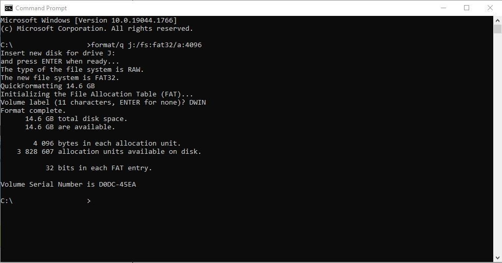
First, open the Command Prompt by pressing the Windows key and typing cmd. This will open a terminal, similar to what you can see on the right side.
Now, you need to enter the following line:
format/q j:/fs:fat32/a:4096
Please notice that there is a space after the letter “q” and the “j” is the letter of your drive. In my case, I am using a card reader to read the SD card and my computer automatically assigned the letter “j” to my card. Always double-check the letter of your SD card, otherwise, you can format something else!
After pressing enter twice, first to apply the above command, then to approve the operation, you will see a few lines showing up, and then it will ask you to enter the name for the drive (SD card). I entered DWIN. As you can see a few more lines showed up, and then the operation was done.
Next, open the freshly formatted SD card from the file explorer and create a folder with the following name:
DWIN_SET
It is very important to create this folder, otherwise, the display will not be able to fetch the files for configuring the display.
Once you’re done, open the folder and copy the files into it from your project’s folder on your hard disk. Remember, that the font file (0_DWIN _ASC.HZK) is originally saved in the root folder of the DGUS software. I always copy it into my project’s DWIN_SET folder after I generated the files so it is easier to find it.

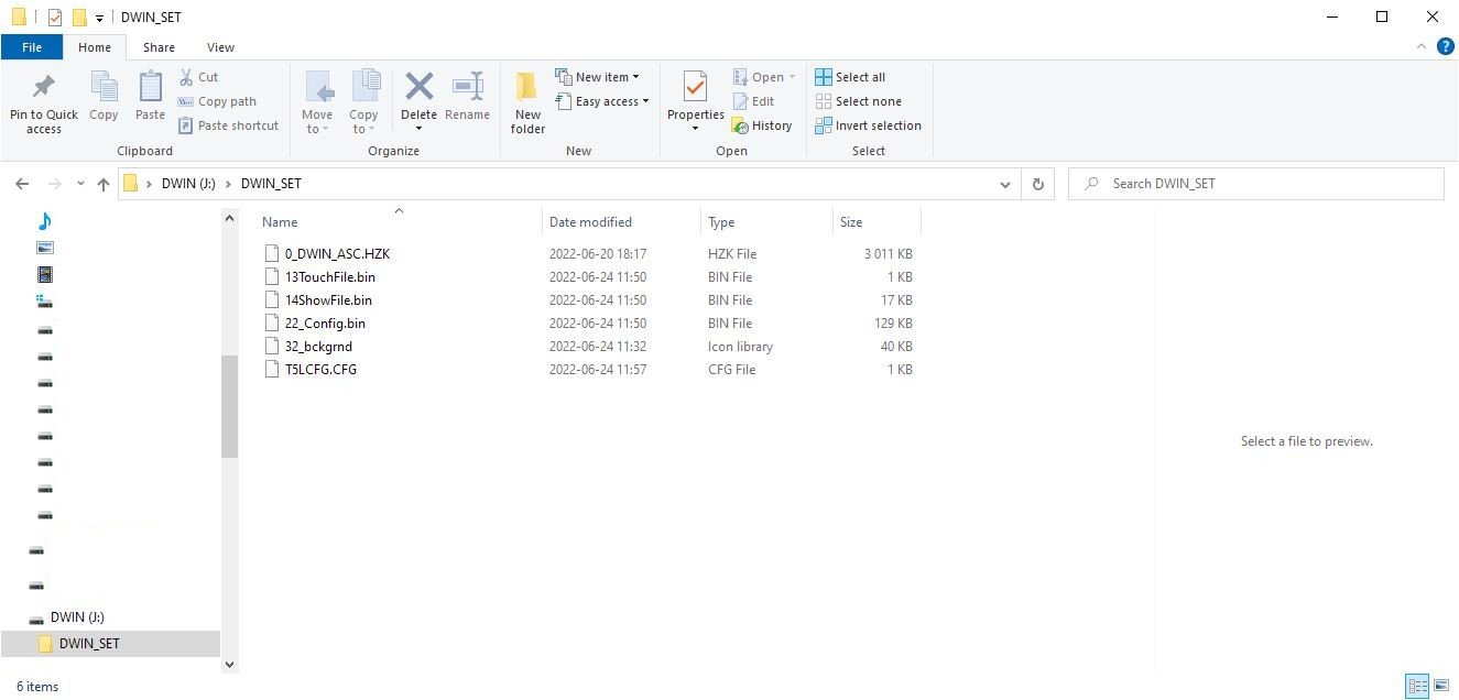
List of files on the SD card:
Font file (0_DWIN_ASC.HZK)
Touch control file (13TouchFile.bin)
Display control file (14ShowFile.bin)
Variables initialization file (22_Config.bin)
Image file (32_bckgrnd.icl)
Hardware configuration file (T5LCFG.CFG)
Once all the files are on the SD card under the DWIN_SET folder, put the card into the display while the display is OFF! After the card is inserted, you can connect the display to a power source. If everything is correct, you should see a blue display that is showing you the progress of the uploading from the SD card to the display. It shows you which file is being transferred at the moment and at the end of the process, there will be a message at the top of the screen (2nd line) which says:
SD Card Process… END !
Once you see this message, unplug the display from the power source and then remove the SD card. Now, without the SD card in the slot, power up the display again. If you followed my instructions properly, you should see the background picture you have uploaded and you should be able to interact with the display.
From this point, you can upload modified code to the display via USB, but only the files starting with 13, 14 and 22 numbers. I could not find a way to update everything on the display via USB, so if you want to make a change, it is better to stick to the SD card uploading method. The USB connection is used for communicating with the display but not programming it!

DWIN display during the data upload process from an SD card
Testing the uploaded code
Here I show the results of the above coding and uploading exercise.
I used RealTerm to capture the serial communication as well as to send data to the display.
First, I pressed the “LED button” on the display. The following line showed up at the terminal:
5A A5 06 83 30 00 01 00 01
The above line shows the header (5A A5), it tells that six bytes is the total amount of data (06), a reading (83) command was performed, the data comes from the (3000) VP address, the returned data length is 1 word (01) and the returned data is (0001).
Then, I touched the slider area at a random place which resulted in 621 as the output value. The response on the serial terminal was:
5A A5 06 83 10 00 01 02 6D
We can see the header (5A A5) as usual, then we see that six bytes are the total amount of data (06), a reading (83) was performed, the data comes from the (1000) VP address and it is 1 word long (01), and the returned data is (026D). 026D is a hexadecimal value; converting it to decimal gives us 621 which is the same number we see on the display. Also, to check the length: [83] + [1000] + [01] + [026D] → 1+2+1+2 = 6. We indeed received 6 bytes.
Finally, I sent the data to the display as the “ADC value”:
5A A5 05 82 20 00 03 DB
Notice that I had to send the above values as 0x5A 0xA5 0x5 0x82…etc, but that is just because of how RealTerm processes the values. Also notice that I have received data (5A A5 03 82 4F 4B) from the display after sending the command. This is just some sort of "acknowledging” message from the display.
First I had to send the header (5A A5), then I sent the number of bytes (05), then the write command (82), then the VP address (20 00), and then the value (03 DB). 03DB is 987 in decimal which is the same number which showed up on the display after I sent it to the command.


Final thoughts
Initially, it was a bit difficult to understand the principles of these DWIN displays. But after some time, I got the hang of it and I started to understand how to work with the display. They are really cheap but powerful devices and they can serve a lot of projects. In exchange for their extremely good value-to-performance ratio, you pay a bit more in time while learning how to work with these displays.
They have a very detailed handbook of nearly 200 pages for the different functions, but sometimes I felt difficult to understand the descriptions in it. Also, there are a few funny words (probably mistranslations) used in the DGUS software that can confuse the user. Nevertheless, they have a very helpful support staff and you can ask them by email or via WhatsApp if you get stuck.
I have many projects in my head where I can use this display, so I will make a YouTube playlist for my tutorials on these DWIN displays and I will gradually add more and more videos to it.