Light meter for analogue cameras
In this article, I show you how I built my own light meter for (mainly) analogue cameras. The light meter is based on the CH32V006K8U6 microcontroller and the TSL2591 light meter chip. The device, based on the intensity of the incident light, suggests exposure parameters based on the fixed parameters that are given to the device. It works similarly to digital light meters on the market, but it is cheaper and fully DIY, so other people can replicate it. I already built the electronics and developed parts of the code in my previous project, and in this project, I show the PCB I designed and the program I wrote for the microcontroller.
Introduction
So, I have already laid the foundations of this project when I did my demo video for the CH32V006K8U6 chip with the TSL2591 light sensor. I had already programmed most of the functions back then, and I also came up with a circuit diagram.
But, there was more to be done. I had to design a whole new circuit that incorporates more than just the chip and the light sensor. The circuit of this project operates on a lithium battery, so a charging circuit and a USB connector were added to the circuit. There’s also an OLED display that shows all the information regarding the measured light and the suggested camera parameters. Then, the user must somehow be able to set the parameters to calculate the exposure variables. The code allows the user to operate in aperture-priority and shutter-priority modes. But, apart from the measured light, the formulas need, for example, the ISO value set on the camera. All the necessary parameters can be set by a nice 3-way navigation button. The navigation button might be familiar to those ’90s kids who had MP3 players back then. This is a similar button that was in those MP3 players. The function of the switch is also somewhat similar: one can go up and down by tilting the button, plus by pressing the button in, a third behaviour can be assigned to the action. The program is written accordingly. The button is used for navigating in a menu where we can set different parameters.
The device, as I mentioned earlier, is operated by a battery. I chose a tiny, 150 mAh lithium battery for this project. By some back-of-the-envelope calculations and some rudimentary measurements, the device can operate continuously for 12+ hours (considering a roughly 20% margin). The device is programmed in a way that it goes to sleep mode in 30 seconds if it is left untouched, and it is in “navigation mode”. The device stays awake if it is left in “editing mode”. Toggling the button wakes it up, and the device starts to operate again. The device has a “power-only” USB-C connector. The MCP73831 charging controller chip is set to 200 mA charging current (Rprog = 5k), so the battery can be recharged fairly quickly. The USB-C connector makes the device up-to-date, and it allows the user to charge it according to today’s standards. I mean, no old micro USB or USB-B connectors anymore, it’s 2025!

The TSL2591 light sensor module. This project utilizes the same light sensor.
Circuit and PCB
The circuit is not super difficult; it consists of a few “main sections/components” and a few smaller parts.
The first and most obvious part is the TSL2591 light meter chip. It has the basic circuit around it, which is a few pull-up resistors and a decoupling capacitor. The circuit’s other central part is the CH32V006F8P6 microcontroller. This microcontroller manages the light metering, and it also handles the calculations for determining the correct exposure values. The chip can be programmed via the SWIO pin that is made available on the top side of the PCB, together with a 3.3 V and a GND connection.
The exposure values are printed on the 0.91” OLED display on the other side of the board. The chip also measures the voltage (hence the charge status) of the lithium battery through a voltage divider and filter circuit. The output of the battery is not directly connected to the rest of the circuit, because the light meter operates at 3.3 V (it is not 5 V tolerant!). The output is regulated down to 3.3 V by an LP5907MFX-3.3 low-dropout regulator. Since the battery also has to be managed (charged) somehow, this is realised by an MCP73831T chip. The chip receives the power required for charging from a power-only USB-C connector.
Since the device needs inputs, there is a 3-way navigation switch on the other side of the PCB. This switch might be familiar to those who owned MP3 players in the old days. The switch allows the user to navigate in the menu and adjust the parameters.


Enclosure
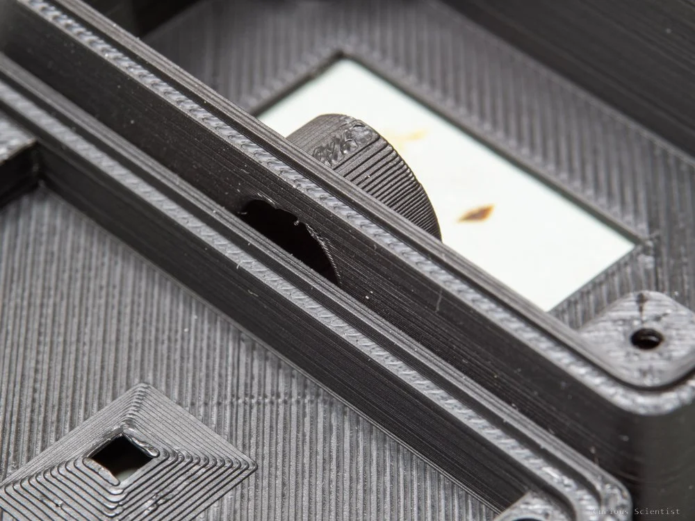
The enclosure of the light meter circuit is fully 3D-printable. It consists of two shells that fit together nicely. The front part accommodates the PCB. The PCB sits in its “seat” tightly. This part of the enclosure has four insert nuts (M2x4x3.5) because the whole enclosure is held together with bolts. There’s also a recessed hole precisely in front of the TSL2591 sensor.
The back side of the enclosure has the four screw holes for the screws that go into the insert nuts. There is a fifth hole at the bottom of the enclosure, which is made for the 1/4” insert nut that allows the enclosure to be attached to an adapter that goes into a standard cold shoe mount. On the back side, there is a rectangular opening that matches the visible area of the 0.91” OLED display.
The enclosure is more or less optimised for size. Its main limiting factor is the size of the PCB. Probably, the PCB could have been further miniaturised, but I wanted to keep it simple and easy to be manufactured by hand. The OLED display and the battery are also limiting the size. Perhaps the battery could be replaced with a CR2032 battery, and the display could go directly on the PCB, but both these decisions make the module more difficult to use. Changing the battery would be cumbersome because it would require the user to disassemble the whole enclosure. Plus, if the display were closer to the PCB, it would make it difficult to find a place for the battery.
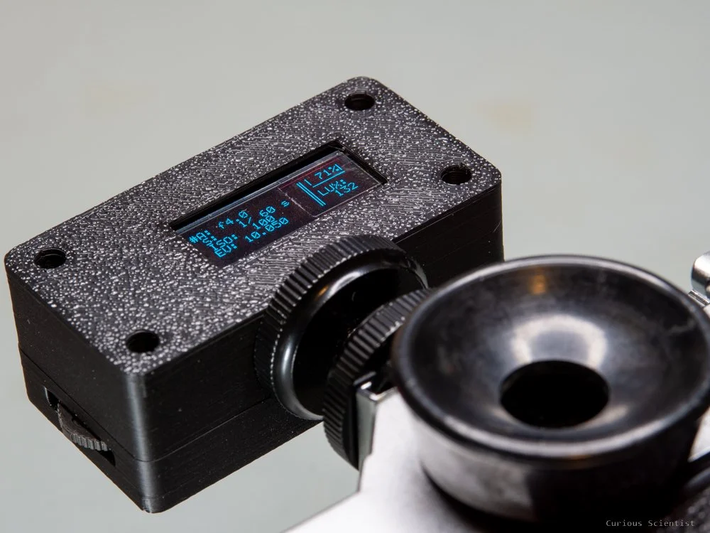
I also made an alternative rear shell that skips the 1/4” insert nut and the corresponding adapter, and it slides directly into the camera’s cold shoe mount. It makes the device more low-profile, and it saves a little cost-wise due to the skipped parts. The additional filament and printing time are essentially negligible.
The mount is made so that it flexes a little bit when it is pushed into a cold shoe mount, ensuring a solid fit. The material that slides into the mount of the camera is rather thin (2 mm), so it is a good idea to pick a stronger material than PLA. If it is handled with care and one does not bend the mount part, it should not have any problems, but it is better to be safe than sorry.


Assembled device and usage
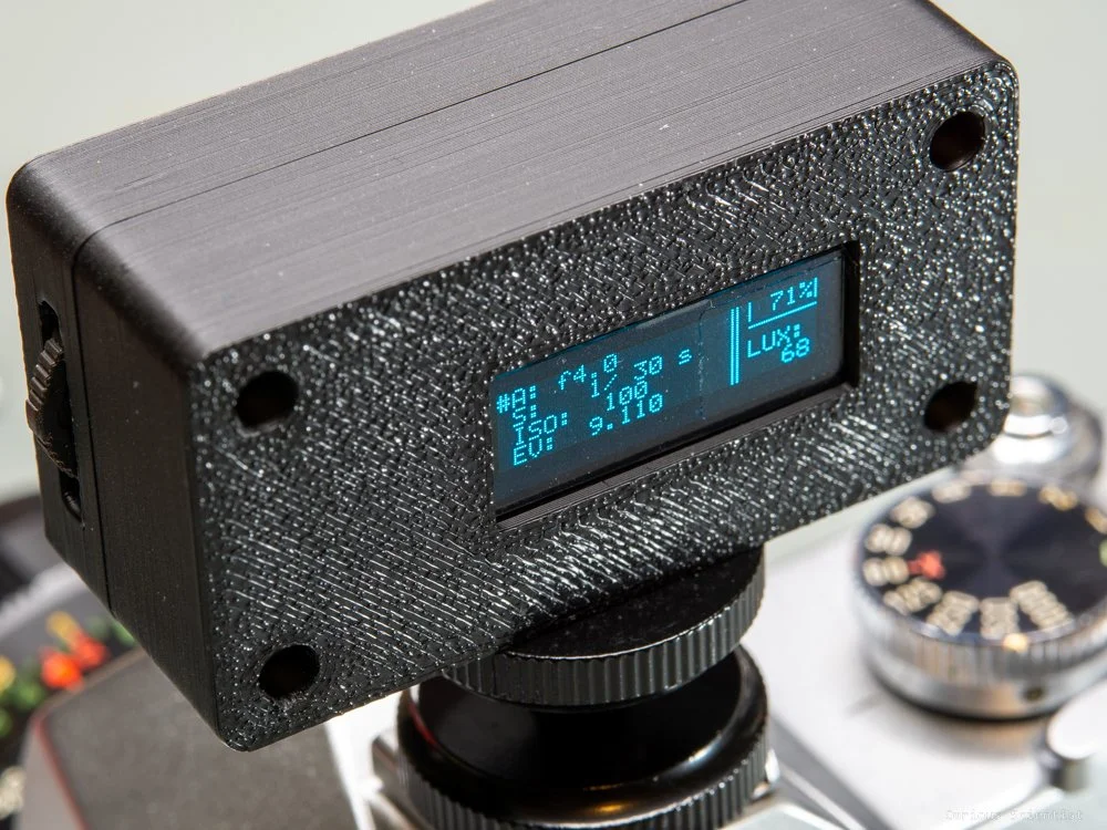
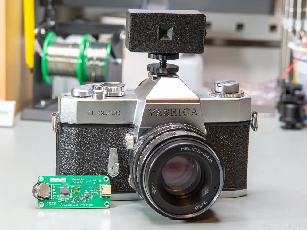
The assembled device with the cold shoe adapter looks fine in my opinion. However, the mounting screw could be a bit shorter, perhaps. The light sensor sits in the centre of the enclosure; therefore, it is perfectly aligned with the optics. The display can be read easily. Both the navigator switch and the USB port are easy to access, so it is not a big trouble to use them.
The device has two modes: navigation and editing. In navigation mode, a “>” symbol indicates the current position of the selector. There are three selectable parameters: Aperture (“A”), shutter speed (“S”) and ISO. To edit any of these parameters, the user must press the navigator switch. Then the “>” symbol changes to “#”, which indicates that the parameter is selected and its value can be changed by tilting the navigator up or down. All the values are pre-programmed. The aperture values are distributed between f1.0 - f22.0 with 1/3 stop step size. The shutter speeds are distributed between 120 s - 1/8000 s. The ISO values are between 25 - 12800. The ISO values and the shutter speed values are probably a bit broader than the capability of the common film cameras, but it is better to have a bit more options than the other way around.
When the light meter is in navigation mode, the device automatically goes to sleep mode after 30 seconds of inactivity. If the device is left in editing mode, it does not go to sleep. When the button is moved, the device automatically wakes up.
Regarding the test pictures, I tested the light meter by attaching it to my digital camera and setting up the exposure parameters according to the values suggested by the light meter. The image of my bench is a bit underexposed, but I think it is caused by the overhead lamp I have over the workbench. The light meter got influenced by the lamp a bit too much, and therefore, it suggested a bit faster shutter speed than necessary. But the image is still OK, so I think it is not an issue. One just must keep in mind that the light sensor is not optimal in small, confined spaces with sharp light sources.


Additional pictures and resources
Get the relevant parts using my affiliate links!
Get the PCB from PCBWay!

Become a channel member!