Updates to the ADS1256 Arduino library and DAQ module
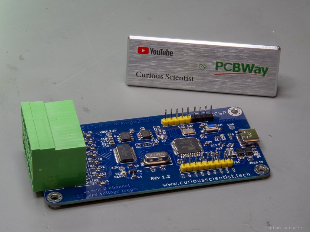
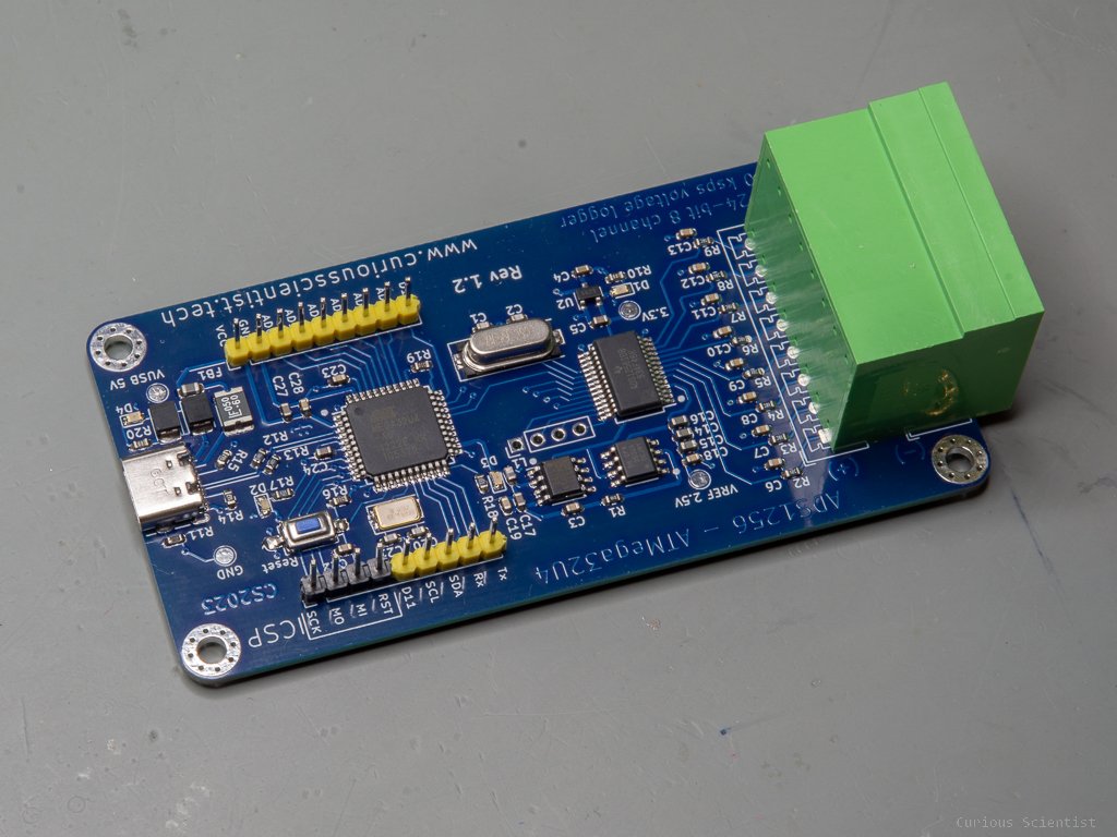
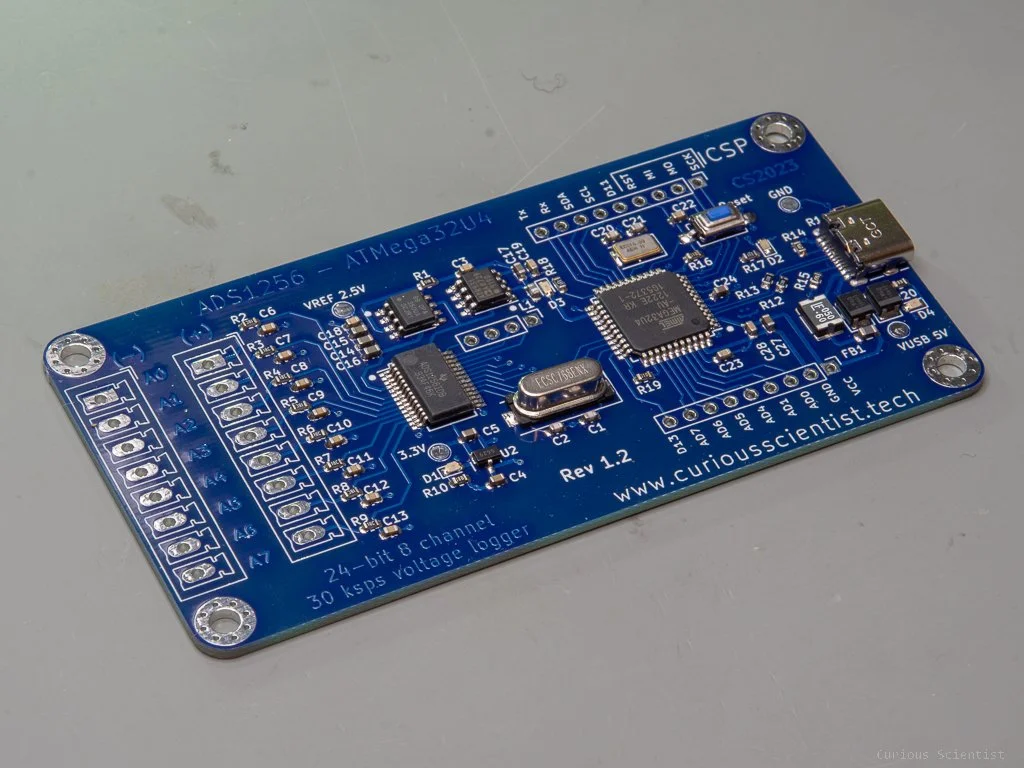
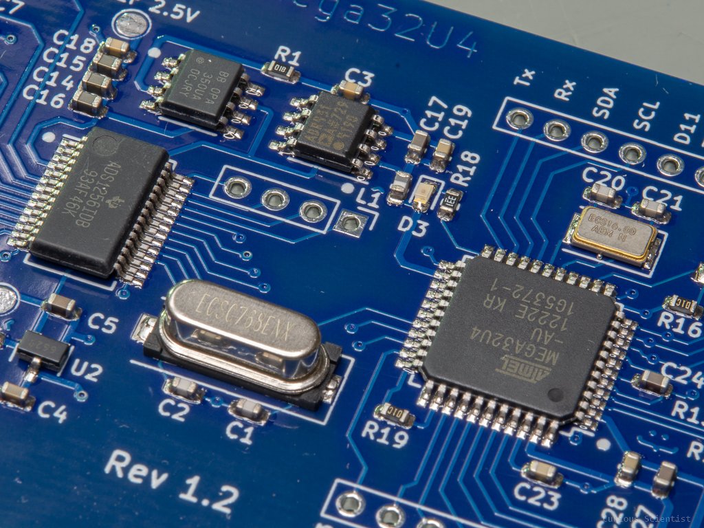
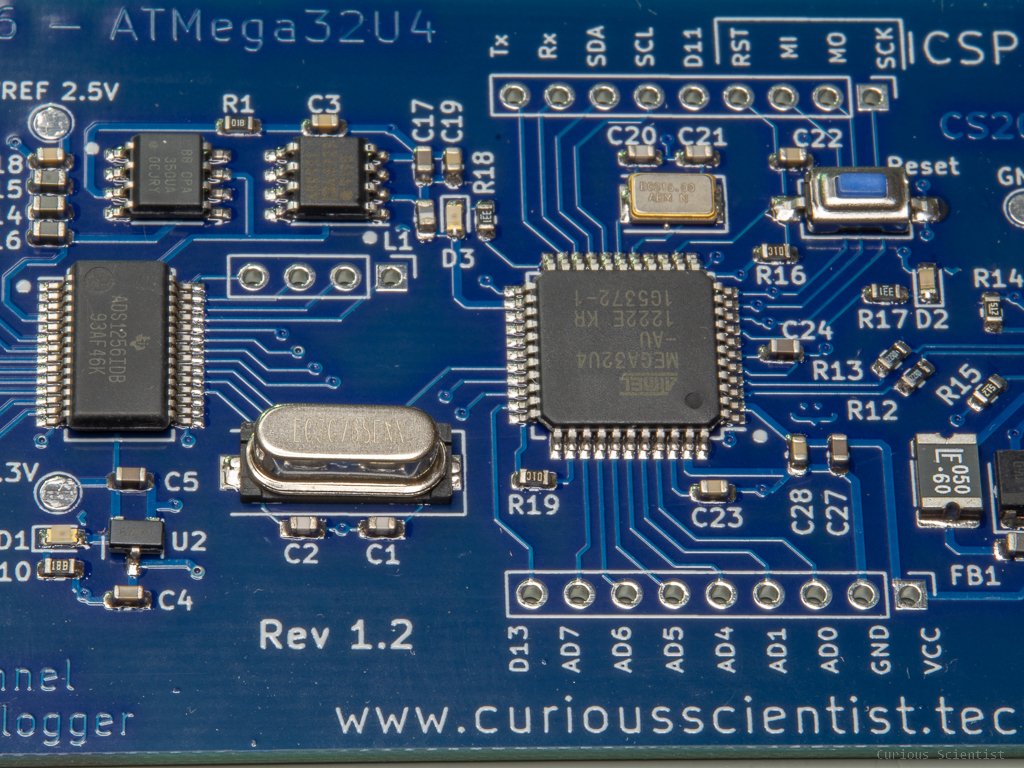
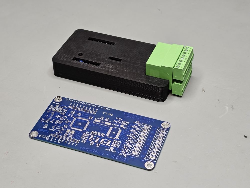
In this video, I show you two things. One is a new version (v1.2) of my custom DAQ based on the ADS1256 AD converter and Atmega32u4 microcontroller. I slightly compressed the size of the board, added a USB-C connector to it, and added some more obvious text on the silkscreen. Another update is the software itself. The library is now officially in the Arduino’s library catalogue. So, if you search for ADS1256 in your Arduino IDE, you will find my code there.
The Library
The ADS1256 Arduino-compatible library has already been discussed in my previous video, so I won’t do it again. It also has a GitHub page and it also has an extremely detailed documentation (see, GitHub page).
I tested the library with eight different microcontrollers so far, and all of them worked correctly:
Arduino Nano*
Arduino Uno*
Arduino Mega 2560*
Teensy 4.0
Atmega32u4
ESP32 WROOM 32
STM32F103C8T6
STM32F401CCU6
*These microcontrollers are probably too slow (or my code is not efficient enough), therefore at 30000 SPS, the actual sampling rate becomes somewhere around 29700 SPS. The other MCUs seem to produce a bit above 30000 SPS at full data rate setting.
If you make use of my library or my design, please consider a small donation. I spent many hours and money developing the code and the hardware. Thank you!

The one and only ADS1256 library in the official Arduino Library Manager
The USB-C connector
The USB-C connector was a bit tricky for me, so I want to share this information hoping that it can help other people.
This specific USB connector (USB4105-GF-A) has two D+ and two D- pins. According to the information I read on the internet, these pins have to be connected together. However, there is a small issue, which is spacing. The pads of D+ and D- are really close to each other and they are not directly next to each other (e.g. D+, D+, D-, D-), but in alternating order (e.g. D+, D-, D+, D-). This means that the traces have to cross each other.
I solved the issue in the following way, and it seems to work reliably. In the schematics editor of KiCAD, I drew the connections according to the specifications. The USB-C connector requires a 5.1k resistor (R14 and R15) on CC1 and CC2 connectors in order to provide 3 A power. This is actually not needed for this board because it will never consume so much current. Then I connected the two D- pins together and connected a 22 Ohm resistor between the connector and the microcontroller. I repeated the same for the D+ pins. These resistors are Atmega32U4 specific, so always discuss the datasheet of your microcontroller to see how the USB line should be treated. I also pulled the shield pin to the ground (GND) using a 1 MOhm resistor.
On the PCB layout, you can see that I connected the D+ and D- tabs together in a similar way. First, I pulled the traces out towards the right side of the tabs (under the connector). Then I added a smaller (0.6/0.3) via to each tab. I tried to keep everything as symmetrical as possible. Then, I connected the vias on the bottom copper layer. I used 0.2 mm wide traces. I also did the same with the VIN tab but with a wider, 0.3 mm trace. Furthermore, I connected all the shield pins (S1) together on the top copper layer. The GND pins are connected to vias relatively close to the pins. The traces are 0.5 mm wide and the vias are 0.8/0.4. The VIN only comes out on one side.

USB4105-GF-A connector on my ADS1256 DAQ board

PCB layout

Via settings

Schematics
Extras
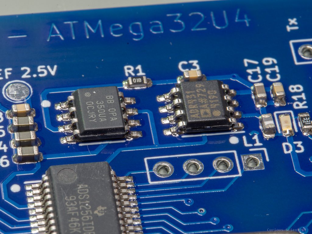
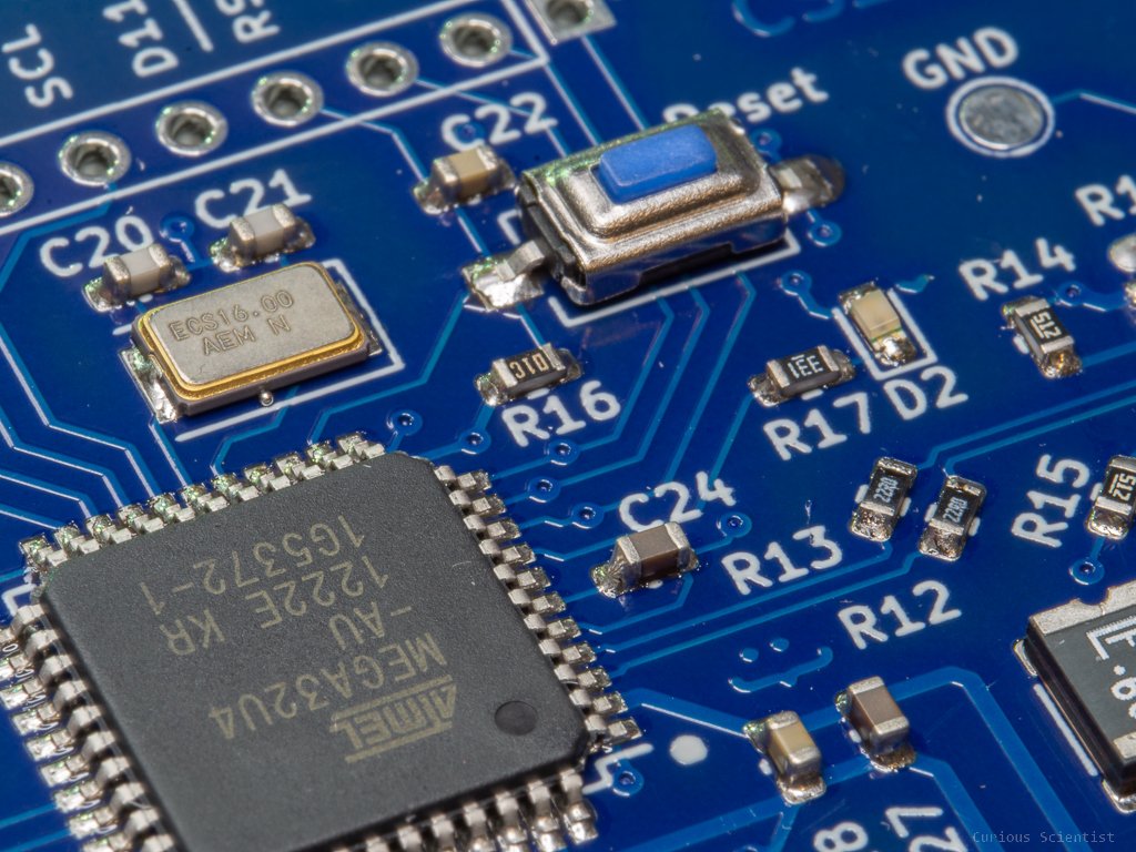
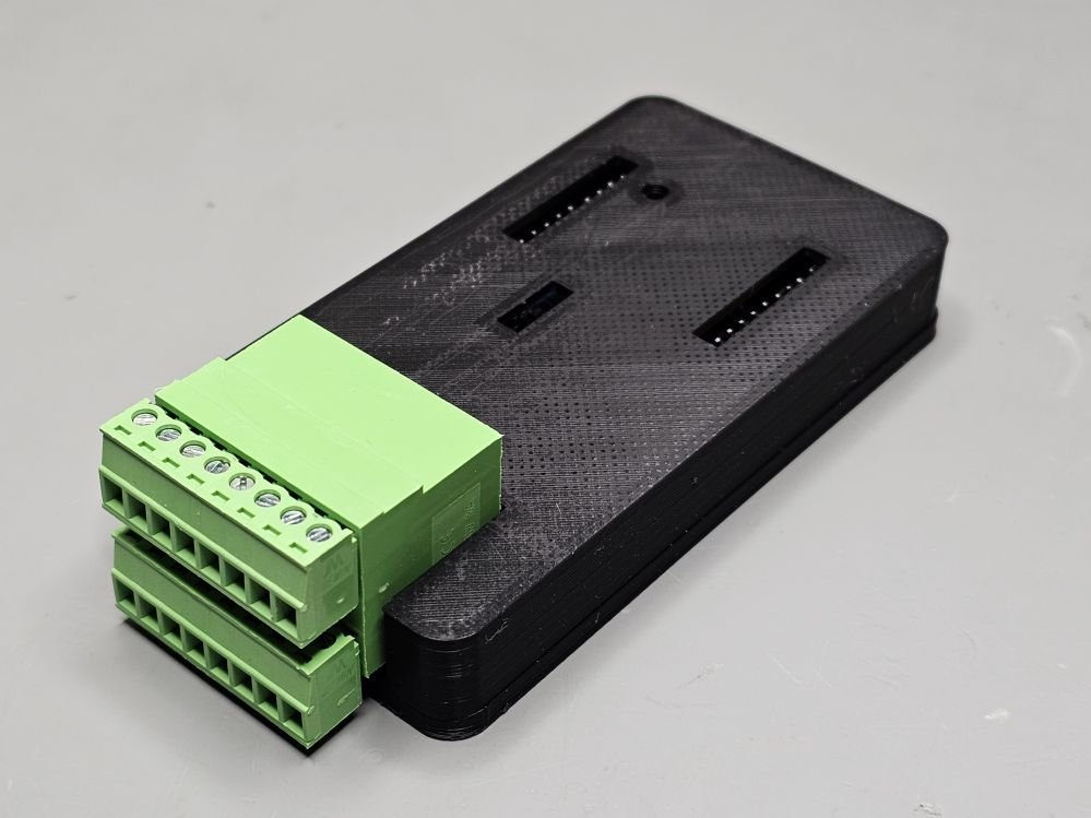
I uploaded a few nice pictures so you can see what my board looks like. I also added some links to different microcontroller boards and different ADS1256 boards. If you don’t want to use my board, but you want to buy the microcontroller and SD converter separately, hopefully, those links will help you.
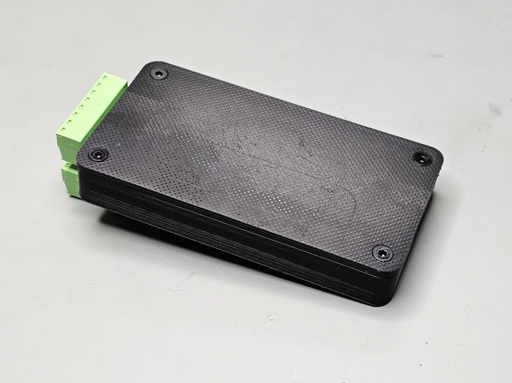
I designed a 3D-printable enclosure (see below in the gallery) for the board. It consists of two pieces, a top piece and a bottom piece. The STL files are available for free on my PCBWay page (see link below) The enclosure requires the following parts:
4x M3x6x5 knurled brass insert nuts
4x M3 nylon washers (id: 3 mm, od: 8 mm, t: 1 mm)
4x M3x10 mm socket countersunk bolts
Please use my affiliate links to purchase the parts
ADS1256 with built-in STM32F103C8T6
Get my board from PCBWay

Join my YouTube membership!