Vertical attachment for the focus stacking rail
In this video, I show you the new accessory I made for my focus stacking rail. In the previous videos [1],[2] I introduced the circuit and the mechanism and now I show an attachment I made to make this system even more versatile.
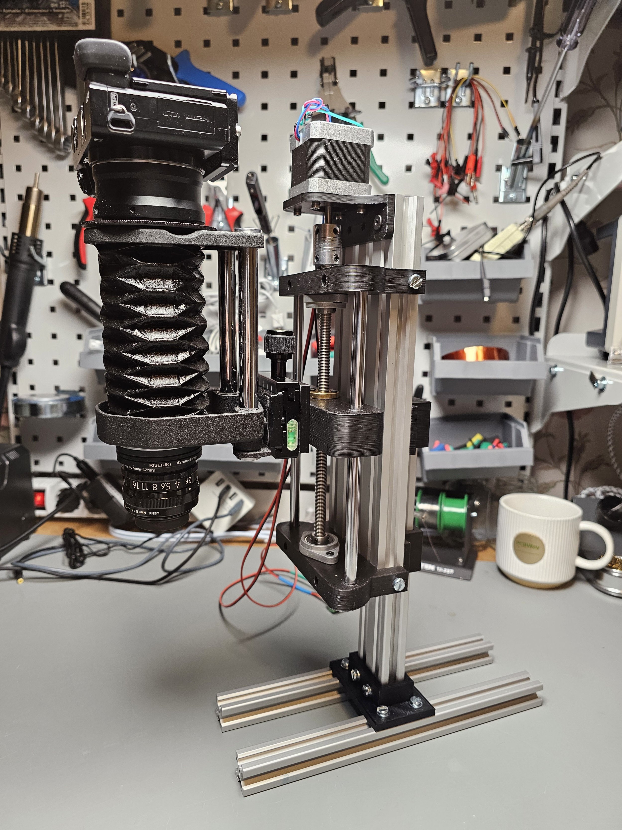
I designed a few 3D-printed parts that can be used together with a few 2020 and 2040 profiles and a handful of bolts and nuts to make my mechanism vertically aligned. Sometimes it is easier to use the rig in a vertical alignment and it also takes up less space. One can also put an XY table under the vertically aligned macro setup and move the subject around more easily.
You will see how you can build this gadget using my 3D models and then I will also demonstrate the capabilities of the rig. Some viewers were asking about the maximum weight it can move reasonably, so I test it in the video. I also check the sag of the structure and some other interesting things.
Extra resources and additional information
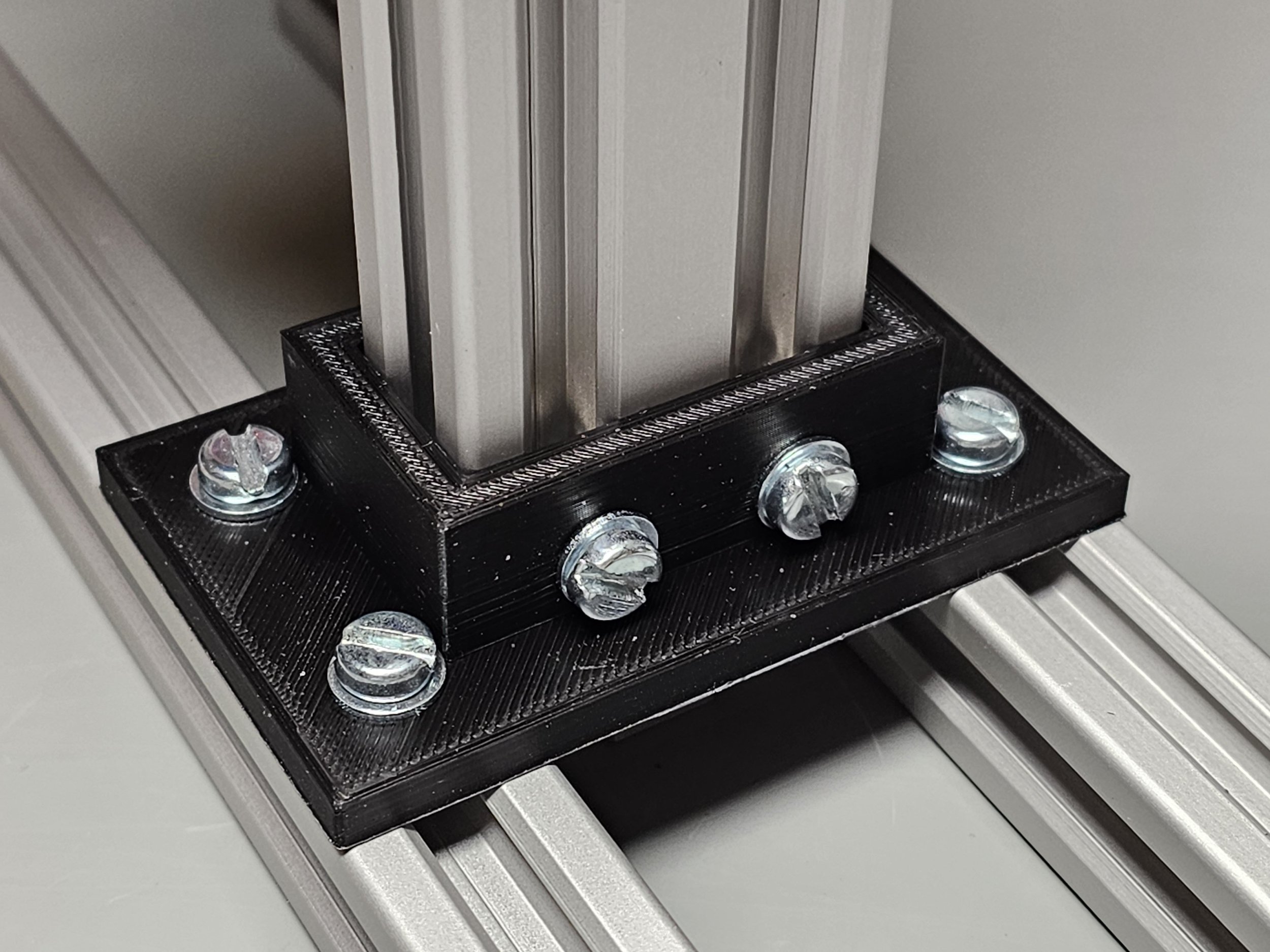
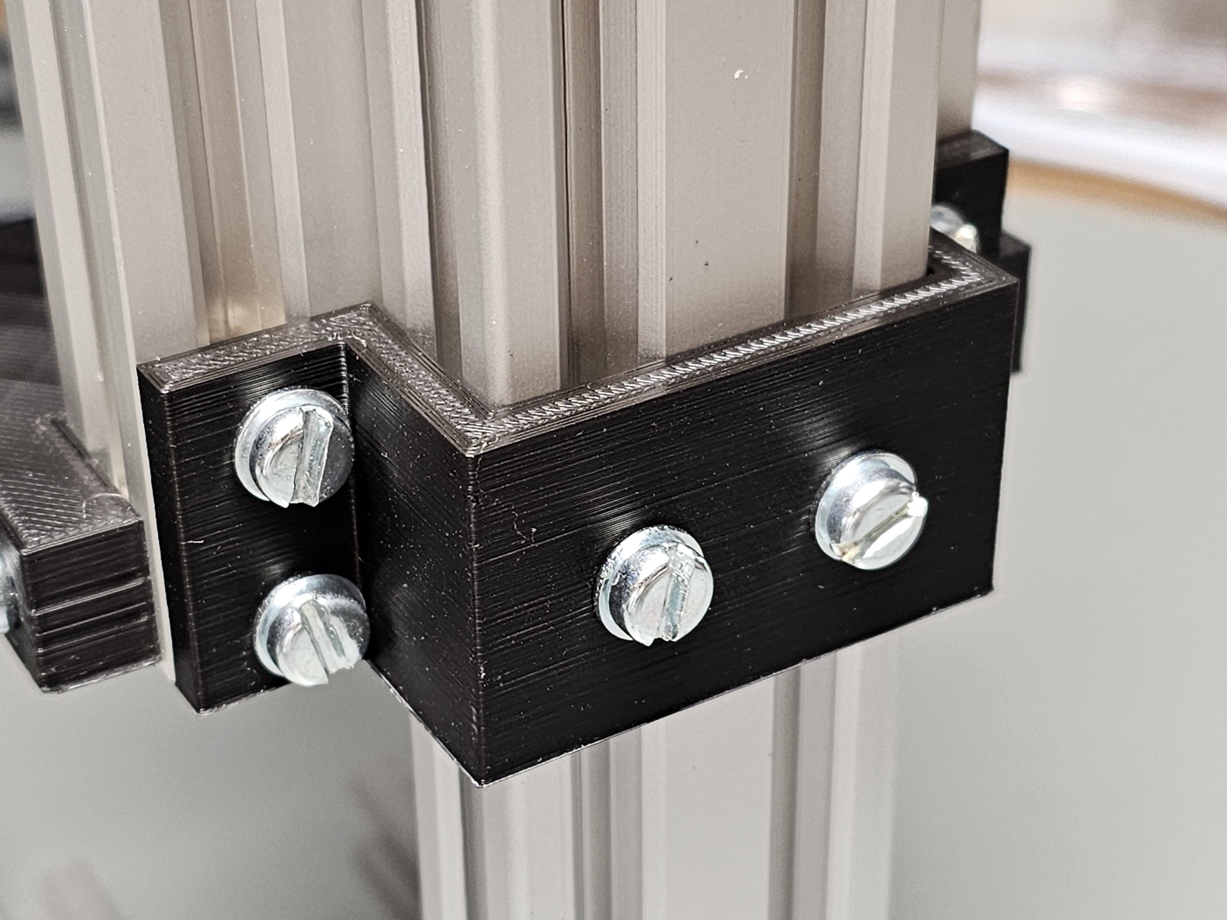
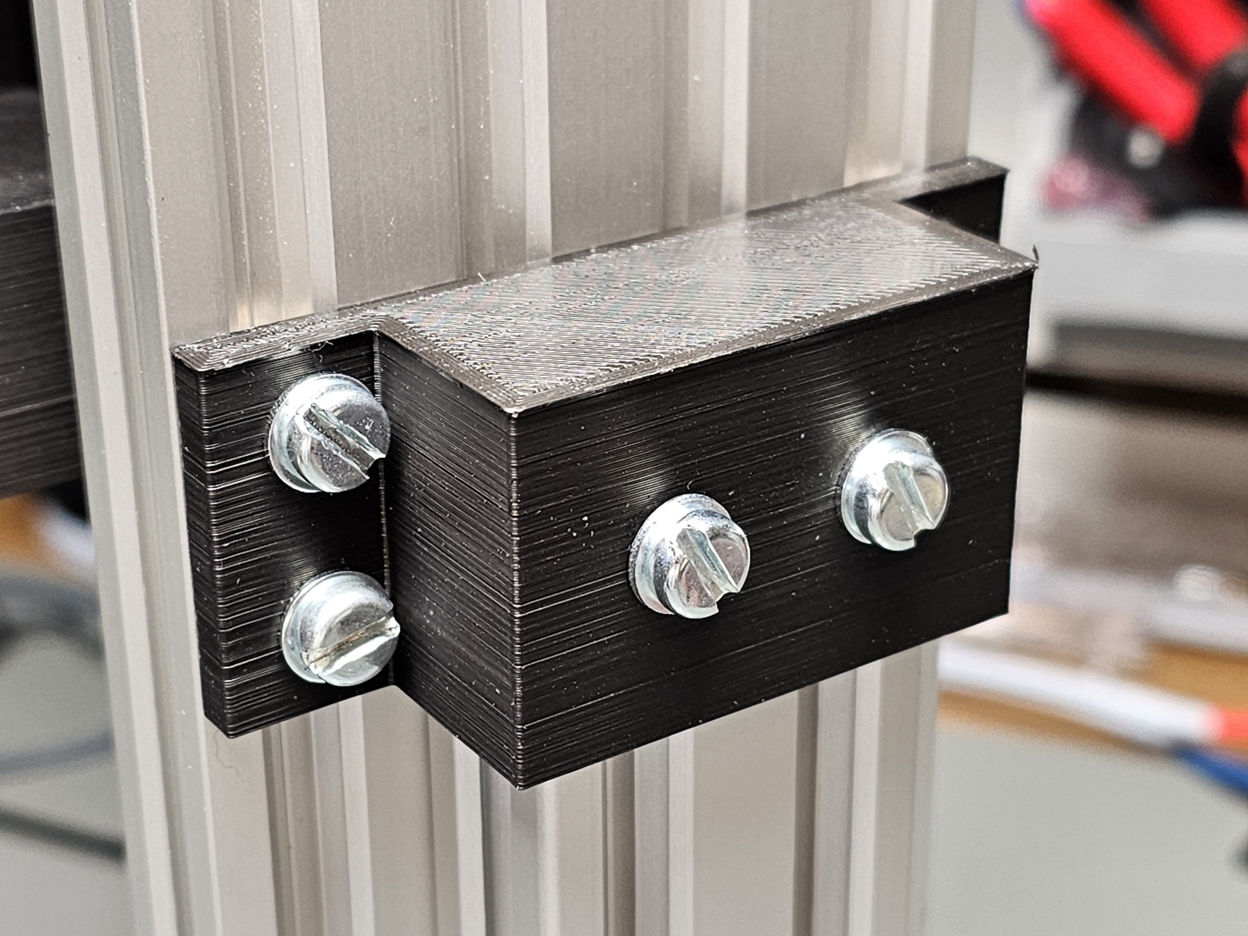
All these three parts are relatively easy to print. I printed them using my Ender 3 Max 3D printer and you can see that the results are not too bad. I used PLA and it seems to be strong enough to hold everything without bending or breaking. The holes were a little tighter than 5 mm, but I would rather have them smaller than larger. It is always easier to ream the holes with a drill bit than trying to figure out what to do with the larger-than-necessary feature. The bolts are regular M5 bolts with 10 mm long threaded parts. I added a washer between the plastic piece and the bolt to avoid destroying the plastic if I accidentally apply too much torque on the screw. I used regular T-nuts to mount the plastic pieces on the profiles.
The “spine”, vertical support is a 250 mm long 2040 (20 mm thick, 40 mm wide) aluminium profile. You can use two 2020 profiles as well, but 2040 is more solid because it is a single extrusion. The vertical piece is attached to the main rig by two pieces. They are nearly identical: one of the clamps has an end cap and the other does not.
Then, the vertical support is attached to two, 250 mm long 2020 profiles. They are used as the feet of the rig. The 3D-printed plastic piece that connects the vertical piece to the feet is really sturdy.
The overall stability of the rig is quite okay. I tried to tip it over (see the video), but I did not manage. Probably, it is easier to tip the structure sideways. So if you need extra stability, you might want to consider adding something that stabilizes the rig sideways.
If you need to get the mechanical parts such as the stepper motor, bearings, lead screw…etc., check the Parts & Tools page on my website. You’ll find everything there.
If you want to print the 3D files yourself, feel free to download the STL files:
If you need to get the parts printed for you, please consider using PCBWay’s services through my affiliate link:
Join my YouTube membership!