Precise focus stacking system - Stepping mechanism
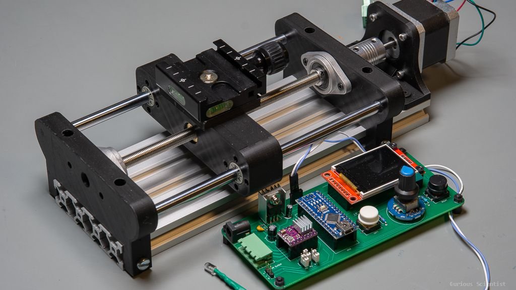
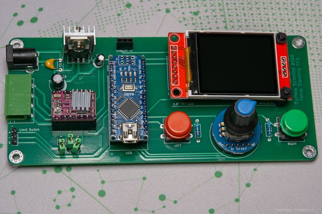
In this video and article, I show you how I built the mechanism from some off-the-shelf and 3d-printed parts that I designed myself. This project has a first part where I introduce the PCB, and a second part where I talk about the mechanism a little bit and explain how the code on the Arduino works.
Details about the mechanism
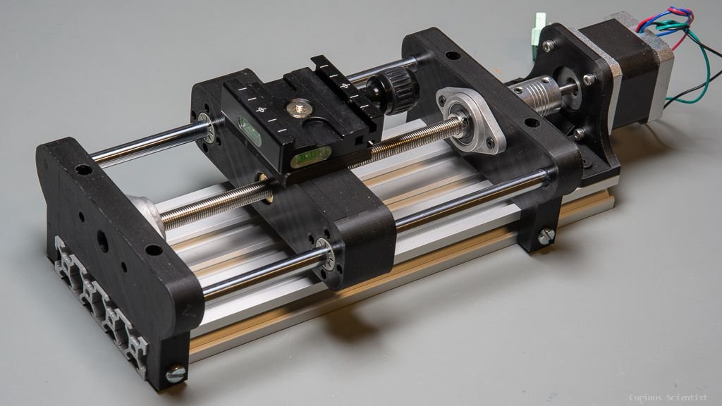
The mechanism's base is a 250 mm long 2080 aluminium extrusion profile. I picked this part because it is stiff, it is easy to source, it is cheap, and it is very easy to attach things to it.
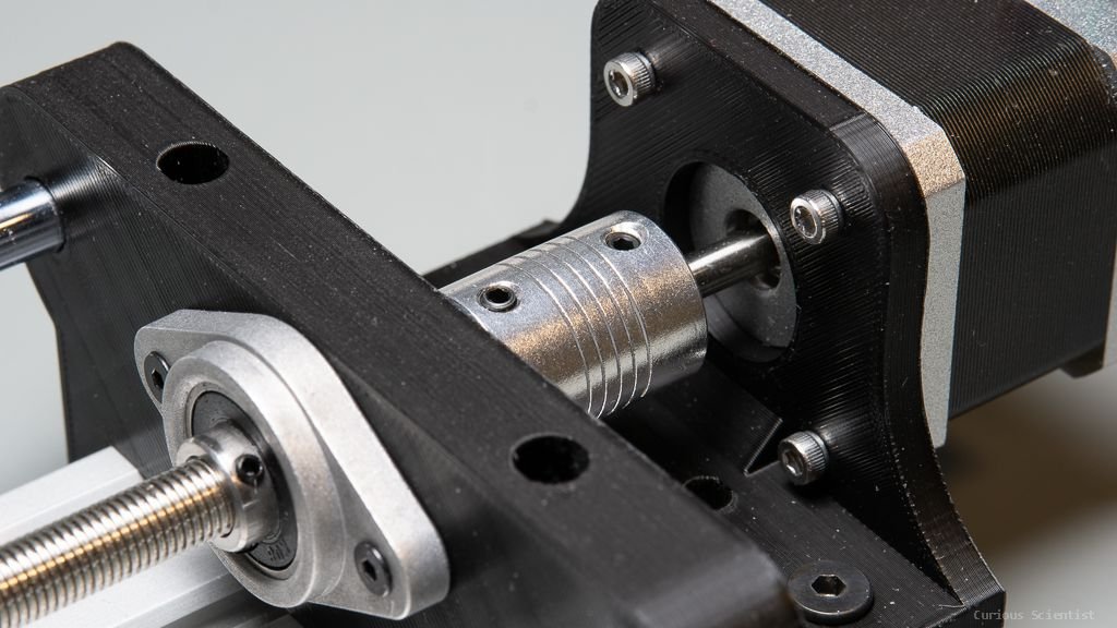
The mechanism is driven by a NEMA 17 stepper motor. The motor is mounted at the end of this 250 mm long profile by a bracket that I designed for this purpose using four M3x10 bolts. The bracket is attached to the 2080 profile by four M4x10 bolts and corresponding T-nuts.
Continuing the chain from the motor, there is a 5 mm to 8 mm flexible coupler. This allows the power transmission between the shaft of the stepper motor and the lead screw. The lead screw is an 8 mm diameter, 200 mm long and 1 mm pitch version. The 1 mm pitch provides quite a small step size even when the motor is at the full step (1.8° / step) setting: 5 micrometres. Further increasing the microstepping, the theoretical step size can be brought below a micrometre. The lead screw drives a spring-loaded anti-backlash nut. The anti-backlash nut has tightly spaced holes, so I just directly screwed M3 bolts in the holes on the 3d-printed crosshead.
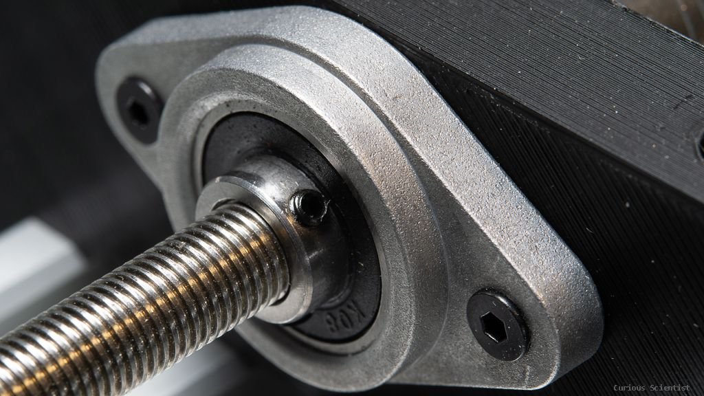
The lead screw is supported by two KFL08 flange bearings. The bearings are held by custom-designed 3d-printed supports at each end of the linear rails. I designed these pieces so they fit the 2080 profile perfectly. The supports are attached to the 2080 profile by 4 screws each. Two from each side of the profile (M4x15 hex), and two from the top (M4x10 hex). The bearings can be attached to the supports in two different ways: either by pressing the M4 insert nut in the holes and attaching the bearings to these insert nuts (I used this method) or by using longer M4 or M5 bolts that go through the whole support. In this case, at least 22 mm long bolts should be used.
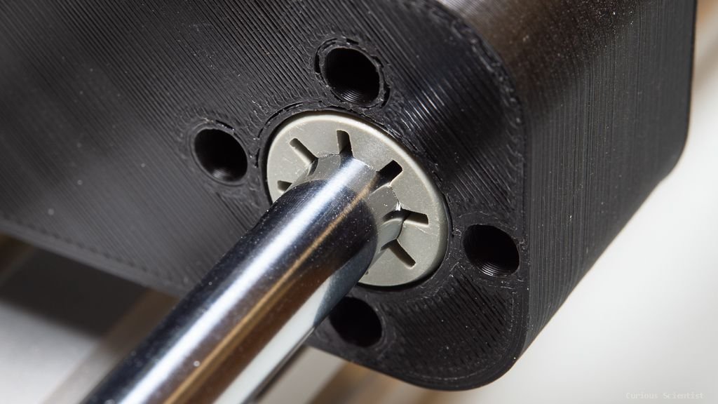
Parallel with the lead screw, there is a linear guide rail on each side of the screw. Both rails are 8 mm in diameter and 200 mm long. These guides snap in their holes in the supports, there is no need for adhesives or bolts...etc.
Finally, these guides support a so-called crosshead. This crosshead has the anti-backlash nut fitted in it and it is driven by the lead screw. It also has two Drylin Igus linear sliding bearings to support the linear shafts. The crosshead can be closed by a cap after inserting the Drylin bearings. There are four holes around the bearings on each side for tightly attaching the cap to the crosshead.
There are four, 5 mm diameter holes on the top of the crosshead. They support the mounting plate for the camera quick-release plate. You can use 4 mm insert nuts in these four holes, or directly use 5 mm bolts. As you turn them in the holes, they will cut the thread for themselves. The holder for the quick-release plate has a 6 mm hole in its centre. I directly bolted an M6 bolt in the hole (1/4" camera bolt also works).
PCB Project page

Mechanism project page
Further resources
If you would like to get the source code for Arduino, please consider supporting me via YouTube membership!
Purchase the components using my affiliate links!
1 mm pitch lead screw with anti-backlash nut
Join my YouTube membership!