Strain gauge, Wheatstone bridge, differential amplifier - Educational device
In this video, I show you a little device that I built so I can explain more things related to strain gauges, Wheatstone bridges and differential amplifiers. My circuit is not new, in fact, I reverse-engineered an already existing circuit from the internet. The circuit is an easy-to-find strain gauge amplifier module. It is a neat little circuit with a built-in Wheatstone bridge and a dual OP-AMP (typically an LM358 or a TP09) with a potentiometer to shift the output voltage. I already used this circuit in some of my older videos.
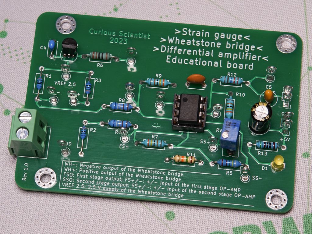
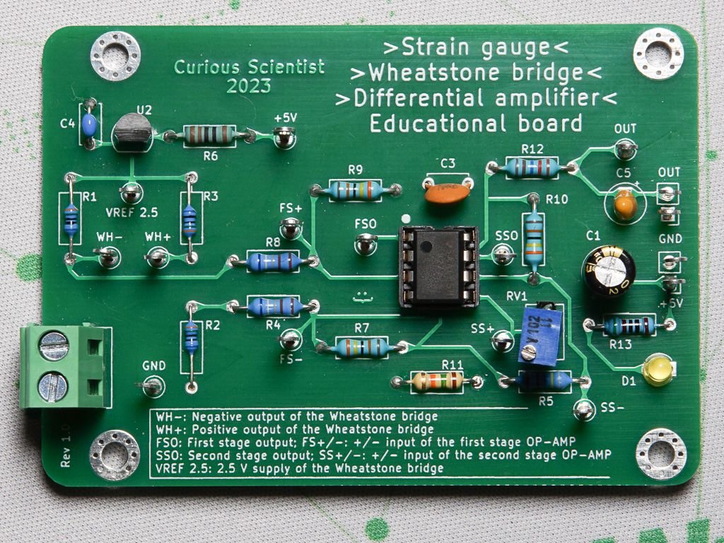
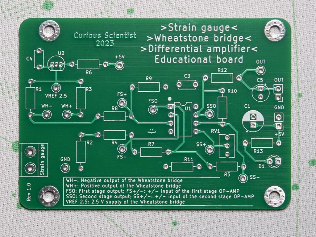
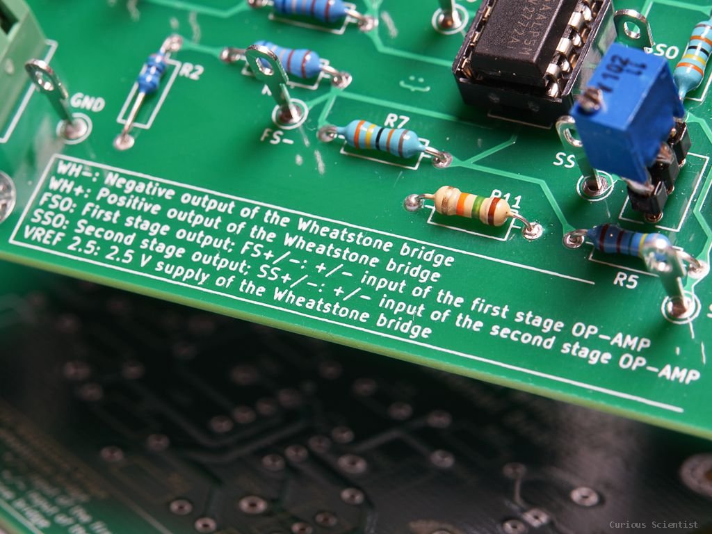
The original circuit is made with SMD components, so it takes time and effort to understand the circuit. I know that there are schematics shared on the internet, but as a practice, I first reverse-engineered the circuit with a multimeter in continuity mode, and then I looked at the publicly available schematic to see if I made any mistakes. Then, I designed a PCB with through-hole components to make it easy to replicate. I added a bunch of test points to places where it can be interesting to measure the voltages. I designed the board in a way that it can potentially be used for example in an electronics lab at a school where the students have to learn about strain gauges, Wheatstone bridges and operational amplifiers. I think this circuit is very useful to understand the concepts of these previously mentioned components.
Theory, explanation and demonstration
This circuit is a great circuit for demonstrating multiple interesting concepts within the subject area of electronics. It has a strain gauge which is an interesting tool to convert deformation (strain) into an electrically measurable signal (resistance). This strain gauge is placed in a (quarter-bridge) Wheatstone bridge which allows us to convert the change of the resistance of the strain gauge into a change of output voltage of the Wheatstone bridge. This is really useful, because it is simpler to measure voltage changes than resistance changes, especially because when the strain gauge is deformed it only changes its resistance with a fraction of an Ohm.
However, the output signal of the Wheatstone bridge is still low, it is in the order of a few milliVolts. Therefore, an operational amplifier is used in a differential amplifier configuration to amplify this low voltage. This part is constructed in a way that the gain of the differential amplifier is almost 50. Then the output voltage of this amplifier stage is further amplified with another similar stage. However, there’s a trick here which is that there is a potentiometer added to the non-inverting input of the operational amplifier. This can offset the final output voltage which would allow us to have both tensile and compressive strains while always producing positive voltages. This is very important because the voltage is limited between 0-5 V. This is a single-rail circuit, there is no negative voltage rail, so the output voltage cannot swing to the negative side when the strain gauge is compressed. Instead, we can set the output voltage of the unstrained strain gauge to be 2.5 V using the potentiometer, then compression would increase this voltage, and tension would decrease this voltage. Thus, we could utilize the full 0-5 V range and half of it is reserved for compression and the other half is reserved for tension. However, it is not entirely perfect, and I will explain it why below.
The strain gauge
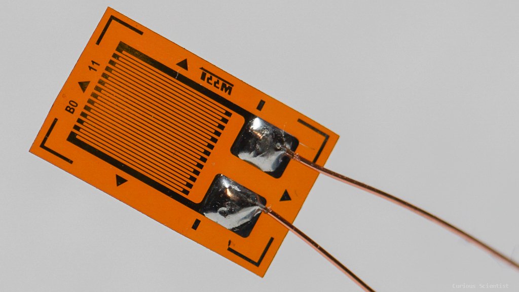
A closeup photo of a typical 350 Ohm strain gauge. The cables were presoldered.
First of all, we have the strain gauge. A strain gauge is basically just a thin long wire wrapped up and placed on a polymer carrier. The strain gauge can be stretched by roughly 2%. When the strain gauge is stretched (or compressed) in its sensitive direction, the wire in it also stretches which results in a change in its resistance. The strain gauge I use (see picture) is sensitive along its long side.
Typically, strain gauges come with 120, 350 or 1000 Ohm nominal resistance. Then, the small change of resistance is added upon, or subtracted from the nominal resistance. The material of the conductive grid on the strain gauge is usually made of constantan, which is a high-resistivity material. It has roughly 30 times higher resistivity than copper, so it is a good candidate for this purpose. If we were to produce the same grid out of copper, it would be only 35 Ohm. Then, it would be even more difficult to detect for example 0.1% change (0.035 Ohm) in resistance.
Unfortunately, the resistance change of constantan is still very small, typically just a fraction of an Ohm. This is problematic because it is not easy to measure such resistance change directly and in a simple way.
The Wheatstone bridge
Luckily, the second part of the circuit after the strain gauge solves the issue. In fact, the strain gauge is also part of this circuit. The second stage is the Wheatstone bridge. In this demonstration, the Wheatstone bridge is in a quarter bridge configuration which means that 1 out of the 4 resistors in it is the strain gauge. There are other configurations such as half bridge and full bridge, but they are not discussed here. The Wheatstone bridge consists of 4 equal resistors. When the resistors perfectly match, the bridge is balanced and the output voltage is zero. However, upon any small unbalance of the bridge, a non-zero output voltage is produced. Here, the unbalancing is caused by the strain gauge. One of the resistors in the bridge is replaced by the strain gauge. The strain gauge can be also depicted as a variable resistor. Whenever the strain gauge is deformed, it will change its resistance and will throw off the balance of the bridge and an output voltage will be generated on the output of the bridge.
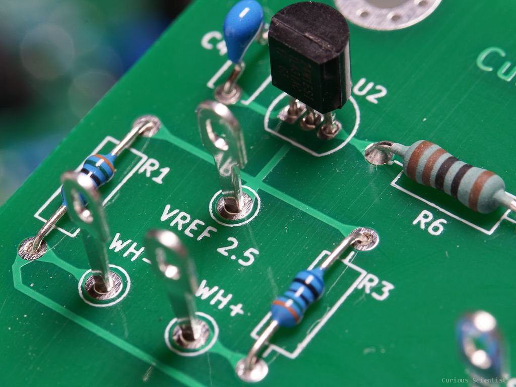
The Wheatstone bridge is powered by a TL431 shunt regulator which provides about 2.5 V. This 2.5 V will be also used for the second stage of the amplification, but that will be discussed later.
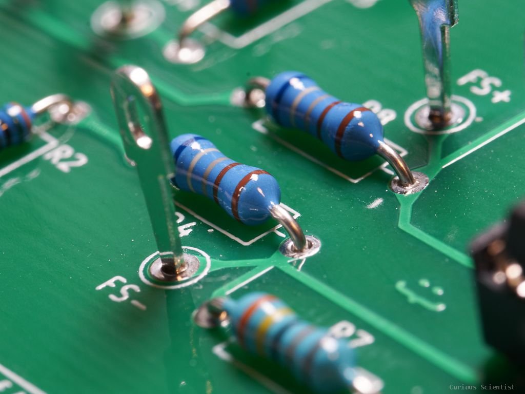
The bridge is constructed in a tricky way which is actually a smart way, but it also has its “dangers”. The three resistors are 348 Ohm resistors (nominal value). They are smaller than the strain gauge which is nominally 350 Ohm. This unbalances the bridge in a way that it will output negative voltage between its output terminals. In other words, the voltage on the WH- terminal will be slightly larger than the voltage on the WH+ terminal even when the strain gauge is unstrained. When tension is applied, the resistance of the strain gauge further increases which makes the output voltage even more negative. On the contrary, when compression is applied, the output voltage becomes less negative. Eventually, it will reach zero volts, but since we have a single-rail configuration, the circuit will stop working properly at this point.
The “danger” is in the combination of the single-rail configuration and the fact that we can hit the 0 V output voltage on the bridge relatively easily if we are unlucky. If the resistors in the bridge differ a lot and if the unstrained resistance of the strain gauge is close in value to the resistors, the output value can be close to 0 V (or it can even go above it theoretically) which would limit the use of the bridge.
I assembled a circuit with 350 Ohm resistors in the bridge, and it started to work weirdly due to the above-described issues.
By using the formula below, we can calculate the output voltage of the bridge based on the values we know.
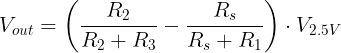
For example, we can say that R1 = R2 = R3 = 348 Ohm, and Rs = 349.5 Ohm, and we can also say that V2.5V is 2.5 V. In this case, the formula gives us -2.688 mV. We get the same result when we create the same circuit in Falstad.
Let’s say that we further stretch the strain gauge and its resistance becomes 351 Ohm. In that case, the output voltage would be -5.365 mV. So, we can see that when the resistance of the strain gauge increases, the output voltage of the bridge becomes more negative.
Now, we compress the strain gauge. Let's not make the bridge fully balanced, so let’s make the resistance to be 348.3 Ohm. After substituting the values in the formula, the output voltage becomes -538.56 uV (microvolts!). The voltage is getting smaller and more positive.
Finally, let’s demonstrate the “wrong” scenario by compressing the strain gauge so much that its resistance becomes lower than the resistors’ values in the bridge. Let’s make it 347 Ohm. In this case, the output voltage is +1.799 mV. This is not an ideal situation for the circuit, we would like to avoid positive voltages. Keep reading to see why.

Wheatstone bridge with the Zener reference circuit.

Falstad simulation of the circuit with “ideal” components.
The differential amplifier - First stage
This output voltage of the bridge has to be amplified because it is in the order of a few milliVolts. It is not so easy to measure it, however, with a good AD converter with a built-in gain amplifier, it would relatively simple. In this article, I pretend that I don’t have at least 20 of the ADS1256 circuit at home, and I show you how to amplify the output voltage of the Wheatstone bridge using a simple differential amplifier. The original circuit uses a TP09 op-amp, but I picked an LM358 in the beginning, and later on, I discovered some more op-amps at home, for example, the TLV2772A which also works just fine.
The first stage is a fixed gain differential amplifier. The resistors are matched in the sense that R4=R8 and R7=R9. This simplifies the calculation a lot because the gain on the inverting and on the non-inverting side are the same.

The above formula gives us (348k/6.98k)*(1.252688 - 1.25000) = 134 mV.
The gain is given by R9/R8 which is 49.85, but Vout/Vin = 134 mV/ 2.688 mV = 49.85 also gives the same result.
Now we can finally see the reason for always expecting negative output voltage on the Wheatstone bridge! If the output is negative, it means that WH+ is lower than WH-. As long as this is true (WH+ < WH-), the first stage will produce a positive output voltage. However if WH- would become lower than WH+, it would be a problem because the output would be clipped. The negative rail on the op-amp is the ground, so we cannot reach negative voltages. This is why I emphasized at the beginning of the article that we need to pay attention that the strain gauge always has a larger resistance than the rest of the resistors in the Wheatstone bridge. If the bridge would produce positive output voltage, we would not get any intelligible values.
Obviously, there are better designs for signal conditioning of Wheatstone bridges, but in this article, I want to explain how this specific circuit works. A proper strain gauge amplifier circuit will be discussed in another article and video. Stay tuned!

First stage of the amplification.

Falstad simulation of the Wheatstone bridge together with the first stage of the amplifier. You can notice that the values differ a little bit as compared to the calculations, but I believe it is just due to rounding errors. And probably because the amplifier slightly loads the bridge.
The differential amplifier - Second stage
Now we have a somewhat more measurable voltage in the order of a few hundred milliVolts, but it could be further improved. Also, we want to use the AD converter of an Arduino, so we also need to make sure that the output voltage will be between 0 and 5 V. Technically, we already achieved it by picking the supply voltage of the op-amp between GND and +5 V, however, we can still experience clipping. This can be mitigated in the second stage by setting the potentiometer properly. As I described in the beginning, the potentiometer can be used to offset the output voltage and “center” it in such a way that we can measure both tension and compression with the circuit.
In this part of the circuit, the output of the first stage is connected to the inverting input of the op-amp. This part of the circuit has a gain of 40.18 which is simply the proportion of R10 and R5.
The non-inverting part is a bit more interesting. Let’s start from the 2.5 V source which comes from the same voltage reference that feeds the Wheatstone bridge. First, there is a 3k resistor, then there is a 1k potentiometer. This can be imagined as 3 resistors in series: R11, RV3-2 and R2-1. RV3-2 is the resistance between pin 3 and the wiper of the potentiometer and VR2-1 is the resistance between pin 2 (wiper) and pin 1 of the resistor.
Of course, all the values should be measured outside the circuit.
Then, we can further simplify this picture because we can add R11 and RV3-2 because they are in series. This makes our job easier when we want to determine the output voltage of this amplification stage. However, for a more instructive demonstration, I put the subcomponents in the formula below.

Let’s first continue our example, which means that the output voltage of the first stage is 134 mV. Let’s also say that the potentiometer is perfectly centred (both RV3-2 and RV2-1 are 500 Ohm). If we substitute everything in the formula, we get 7.485 V as the final output voltage (second stage out). Actually, this is impossible in the current configuration, so we would see VCC (5 V) instead. In other words, the output is clipped. If the potentiometer is in the centre, then the output voltage would be too high. The output would only go down if we would apply a lot of strain on the strain gauge. However, we could not measure this change from the beginning.
Now let’s say that I set the potentiometer in a way that RV3-2 becomes 717.8 Ohm and RV2-1 becomes 282.2 Ohm. We can simulate the “upper part” of the potentiometer and the 3k resistor together with a single 3.7178k resistor, and simulate the “lower part” of the potentiometer with a 282.2 Ohm resistor.
With the above parameters, the output voltage would be 1.879 V. If we compare it to the Falstad simulation, there’s only a very little difference.

Second stage of amplification. This part produces the final output voltage as well.

Simulation of the whole circuit
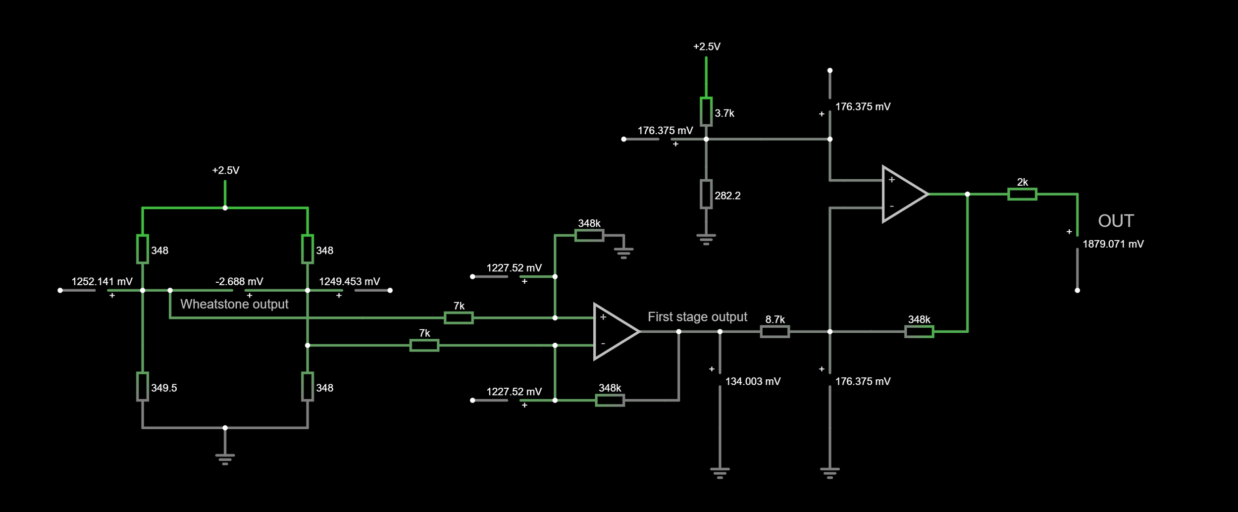
Full circuit simulated in falstad. The only “cheating” I did is that I adjusted the strain gauge resistance to 349.538 Ohm so the output of the Wheatstone bridge matches the output of the “bare” Wheatstone bridge that we calculated in the beginning. After doing this small correction, the rest of the values down the line are all correct and they line up well with the values I calculated manually using the textbook formulas. Please note that I was using the nominal values of the components from the board I reverse-engineered!
As it is shown in the video, there is a noticeable difference (about 60 mV) between the measured voltages vs. the calculated voltages. The calculations assume an ideal op-amp which means that there are no offsets and other issues such as the tolerance of the passive components. When we expect a certain output voltage it is not enough to consider the input voltage as the only voltage parameter. The sum of the input voltage plus the offset voltage that is being amplified by the gain determined by the resistors. So, if the measured voltage (input voltage) and the offset voltage of the op-amp are comparable, it can cause trouble.
I also used resistors with only 1% tolerance, and I did not match them very precisely. I could have bought passives with 0.1% or even with 0.01% tolerance which probably would have yielded much better results.
PCB and other resources
In the section below you can find all the relevant resources that might be helpful if you want to recreate the project. If you find the content helpful, please consider supporting me on Patreon. If you want to recreate the project and build it yourself, you can buy my PCB from PCBWay via my shared project.
I also shared the affiliate link for the original SMD component-based strain gauge circuit. Since I reverse-engineered the circuit, you can also find the schematics. All values are the nominal values of the components on the SMD board, however, I used a different voltage reference (TL431) and a different op-amp (LM358 or TLV2772A).
You can also find the simulation file for falstad. Just go to the website, load the circuit file (File/Open File…) and feel free to play around with the values.
Join my YouTube membership!

PCBWay Project Page

Strain gauge module from the internet. Click on the picture to open my affiliate link.