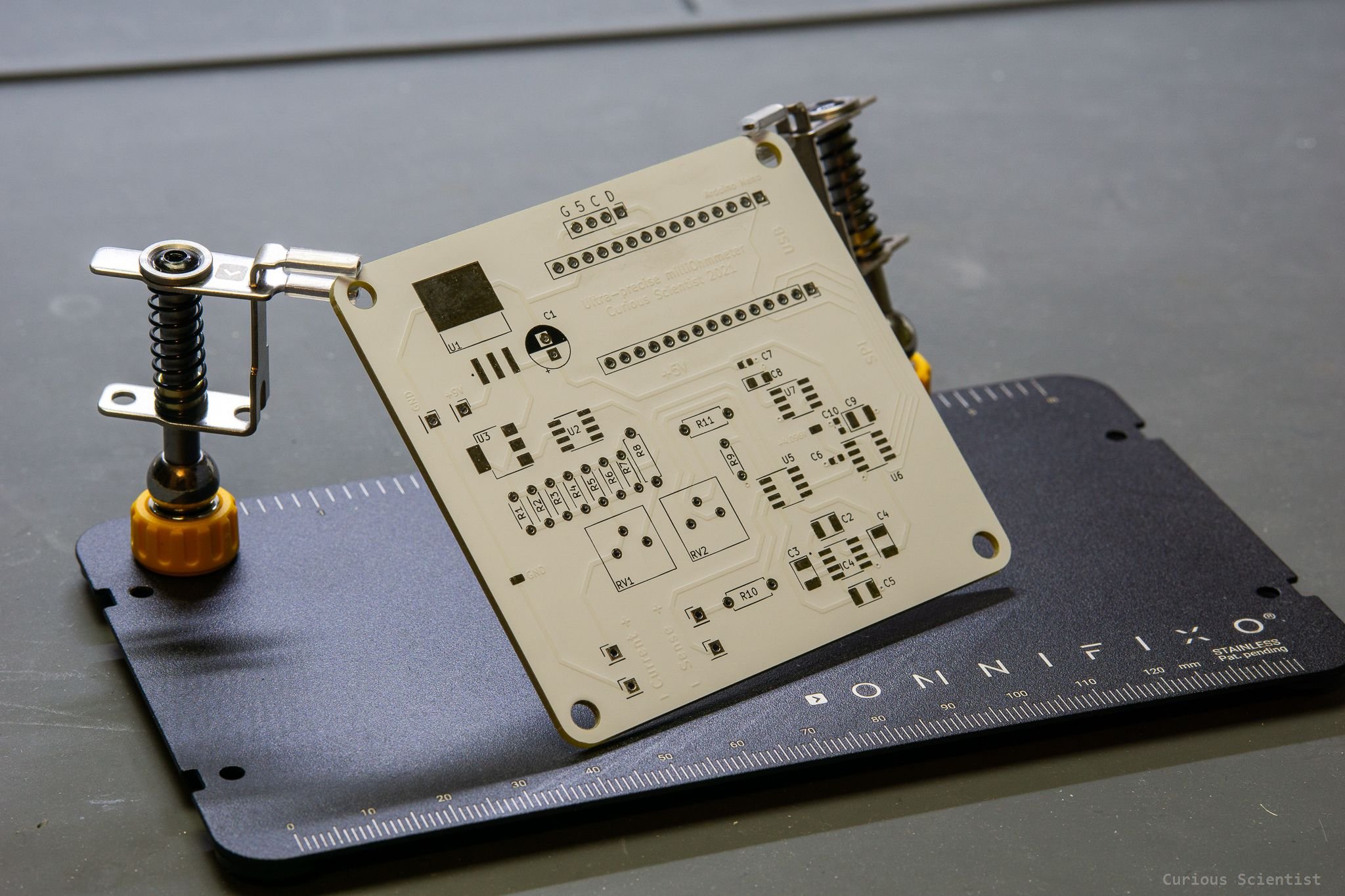
Ultra-precise milliOhm meter - Part 2/2
In this video I demonstrate the capabilities of the device I assembled and then I show you the code. I haven’t done the current and voltage adjustment yet, because I need some precise resistors for the adjustment. Nevertheless, I get reasonably good values already. I show you how the circuit is built up, what components I used and how the measurement is done using the 4-wire sensing clips. I also spend a bit longer time explaining the principles of the AD converter. I show the ADC-readout in a very detailed way because the principles can be applied to most of the AD converters, so it is worth to know how the things work.
Arduino source code
#include <SPI.h> //for the ADC
#include <Wire.h> //for the display

//Display related
#include <Adafruit_GFX.h>
#include <Adafruit_SSD1305.h>

#define OLED_RESET 9
Adafruit_SSD1305 display(128, 32, &Wire, OLED_RESET);
//---------------------------------------------------

const int CS_pin = 10;
long rawADCdata = 0;
long registerData = 0;
float voltage = 0;
float current = 100; //100 mA
float resistance = 0;
float VREF = 4.096;

void setup()
{
  pinMode (CS_pin, OUTPUT);
  digitalWrite(CS_pin, HIGH);

  //For the ADC
  SPI.begin();
  SPI.setBitOrder(MSBFIRST);
  SPI.setDataMode(SPI_MODE0);
  SPI.setClockDivider(SPI_CLOCK_DIV16);
  //-----------------------------------------------------
  Serial.begin(9600);
  //-----------------------------------------------------
  //For the display
  while (! Serial) delay(100);
  Serial.println("SSD1305 OLED test");

  if ( ! display.begin(0x3C) )
  {
    Serial.println("Unable to initialize OLED");
    while (1) yield();
  }

  display.clearDisplay();
  display.setTextSize(1);
  display.setTextColor(WHITE);
  display.setCursor(0, 0);
  display.println("    Ultra-precise");
  display.println("   milliOhm meter");
  display.println("  Curious Scientist");
  display.println("         2022");
  display.display();
  delay(3000);
}


void loop()
{
  calculateVoltage();

  calculateResistance();

  printOLED();
}

void calculateResistance()
{
  //R = U / I
  resistance = 1000 * (voltage) / current; //x1000 -> mOhm (because the current is in mA)

  Serial.print("Voltage: "); //print the average voltage
  Serial.print(voltage);
  Serial.println(" mV");

  Serial.println(" "); //empty line

  Serial.print("Resistance: "); //print the resistance
  Serial.print(resistance, 2);
  Serial.println(" mOhm");

  Serial.println("--------------------------------------------"); //Separator

}

void printOLED()
{
  display.clearDisplay();
  display.setTextSize(2);
  display.setTextColor(WHITE);
  display.setCursor(0, 0); //(x,y)
  display.print("R= ");
  display.setCursor(25, 0);
  display.print(resistance, 2);
  //
  display.setTextSize(1);
  display.setCursor(0, 16);
  display.print("U = ");
  display.setCursor(20, 16);
  display.print(voltage, 2);
  display.setCursor(70, 16);
  display.print(" mV");
  //
  display.setCursor(0, 25);
  display.println("I = 100 mA, fixed");
  display.display();
}

void calculateVoltage()
{
  //Zero the values to avoid mistakes in the summation
  rawADCdata = 0;
  voltage = 0;

  for (int i = 0; i < 10; i++) //read 10x
  {
    rawADCdata += readADC(); //read the ADC, put the raw data into a variable
    delay(200); //wait (conversion time) - see page 4.
  }

  rawADCdata /= 10; //divide it by the number of reads - averaging

  Serial.print("Raw bits: ");
  Serial.println(rawADCdata);
  Serial.println(" "); //empty line

  voltage = rawADCdata * 4.096 / (16777216) * 100; // *100 -> express it in mV (only 100, because the INA106 already gives a x10)
}

long readADC()
{
  //How LTC2400 works? - Manual page 9-10.
  //3 steps:
  //1.) LTC2400 performs the conversion
  //2.) Enters a sleep state
  //3.) Once CS pulled low, the device exits the sleep state and it starts to output the results
  //The data consists of 32 bits. After all is shifted out CS automatically goes HIGH
  //Data format:
  //0000 | 0000 | 0000 | 0000 | 0000 | 0000 | 0000 | 0000
  //  a     b       c      d      e      f      g      h
  //a: status information indicating the sign, input range and conversion state. bit 31 is the EOC -> LOW when conversion is done
  //b to g are conversion. b is the MSB
  //h: sub LSB, can be discarded

  //First, CS must go low to tell the ADC that we want the conversion results
  digitalWrite(CS_pin, LOW);
  //Then, we have to wait the D12 (MISO) pin to become available
  while (digitalRead(12) == 1) {} //we get stuck here until the pin 12 (MISO) is HIGH
  registerData = 0; //zero registerData to start clean

  registerData = SPI.transfer(0xff); //pull out the first byte -- 00000000 00000000 00000000 aaaabbbb
  registerData &= B00001111; //Remove the first four (a-part) bits and keep the rest which are part of the MSB --  00000000 00000000 00000000 0000Bbbb (B = bit27 = MSB)
  registerData <<= 8;         //MSB gets shifted LEFT by 8 bits --  00000000 00000000 0000Bbbb 00000000
  registerData |= SPI.transfer(0xff); //Mid-byte1 comes in and combined with the previous data --  00000000 00000000 0000Bbbb cccccccc
  registerData <<= 8; //MSB+MID1 left shift: 00000000 0000Bbbb cccccccc 00000000
  registerData |= SPI.transfer(0xff); //MSB+MID1 is combined with MID2 -- 00000000 0000Bbbb cccccccc dddddddd
  registerData <<= 8; //MSB+MID1+MID2 left shift: 0000Bbbb cccccccc dddddddd 00000000
  registerData |= SPI.transfer(0xff); //MSB+MID1+MID2+LSB is combined -- 0000Bbbb cccccccc dddddddd eeeeeeee
  //Final, valid part is between the brackets: 0000[Bbbb cccccccc dddddddd eeee]eeee
  registerData >>= 4; //shift out 4 bits (sub-LSBs) // 00000000 Bbbbcccc ccccdddd ddddeeee

  digitalWrite(CS_pin, HIGH);
  return (registerData);
}
Get the PCB from PCBWay
You can order my PCB through my affiliate link using PCBWay’s services. Click on the picture below and you will be redirected to PCBWay’s website.
