Ultra-precise milliOhm meter - Part 1/2
In this video I am going to show you my adventures of building a high-resolution milliOhm meter. I found a great YouTube channel, Scullcom Hobby Electronics and I found two great designs for a milliOhm meter and for a 6½-digit voltmeter.
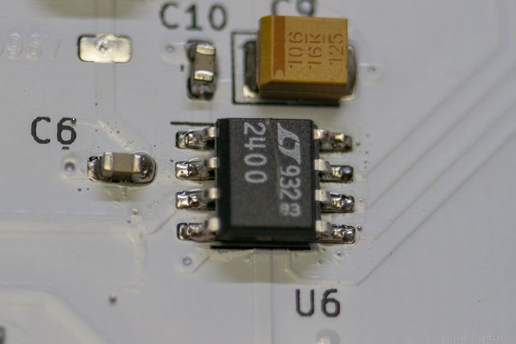
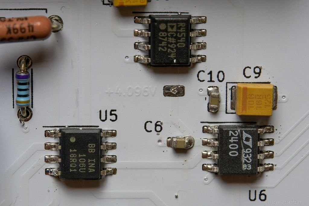
More precisely this and this project. I started studying the milliOhm meter project, but I wanted to have the voltmeter part to be digital as well. Therefore, instead of using a panel meter like he did, I wanted to build an ADC circuit. This is where his second project, or part of it comes into play. I picked the same ADC (LTC2400) and voltage reference (ADR4540B) as he did and I paired the ADC up with an Arduino Nano.
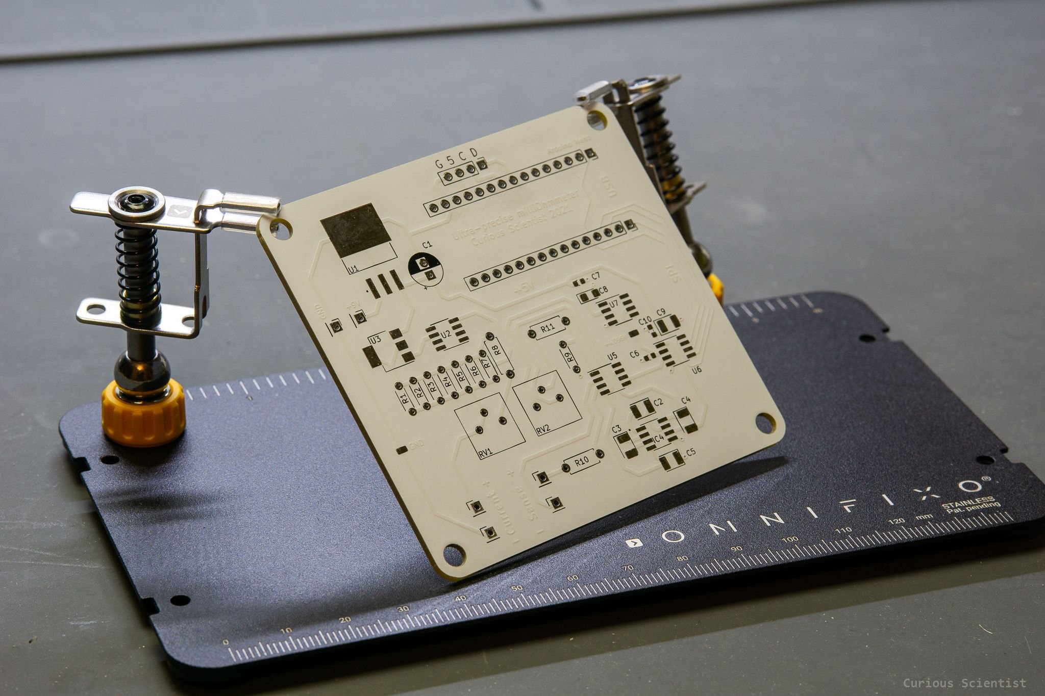
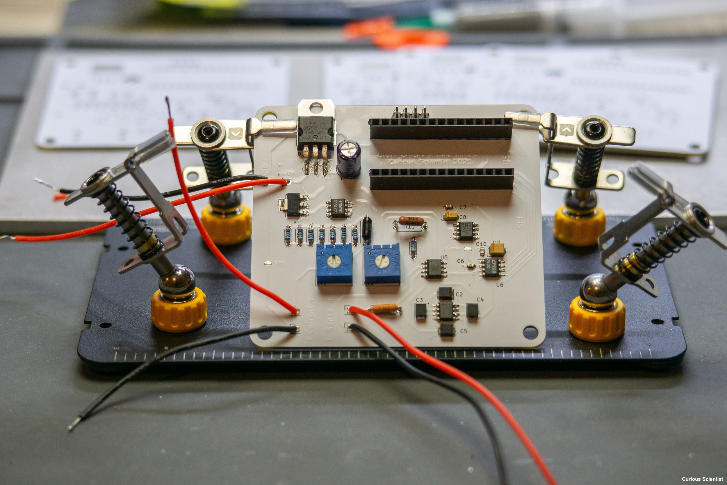
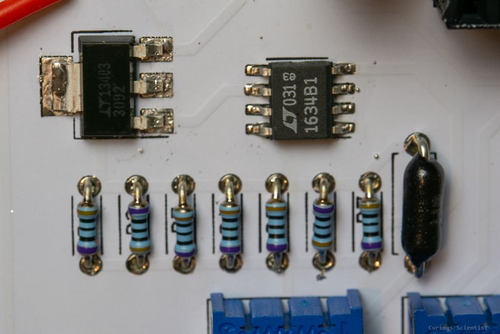
So, I "alloyed" the above two project into one, designed my own PCB, then built the circuit. This part is only about building the circuit and testing a few parts of it.
Some pictures of the board
Use the buttons below to get the schematics and bill of materials.
Get the PCB from PCBWay!
Join my YouTube membership!