LINKMICRO LM249MS microscope with 10” display
In this article, I will show you my new gadget which is a LINKMICRO LM249MS microscope with a 10” display. The device was provided to me by LINKMICRO , but, the article and the video are unbiased and professional reviews of the device. I share both my positive and negative impressions about this instrument.
The device is an excellent tool for troubleshooting and assembling electrical circuits, but thanks to the attachments of the microscope, other objects can also be studied with it. It comes with a lot of different accessories that allow the user to use the microscope for many different purposes.
The package
The microscope arrived with a lot of accessories. First of all, of course, the package contains the microscope itself. The microscope and the 10” display are attached together. The optics and the sensor are attached to the back of the display unit through a hinge mechanism that allows the display to be tilted when it is mounted on the stand.
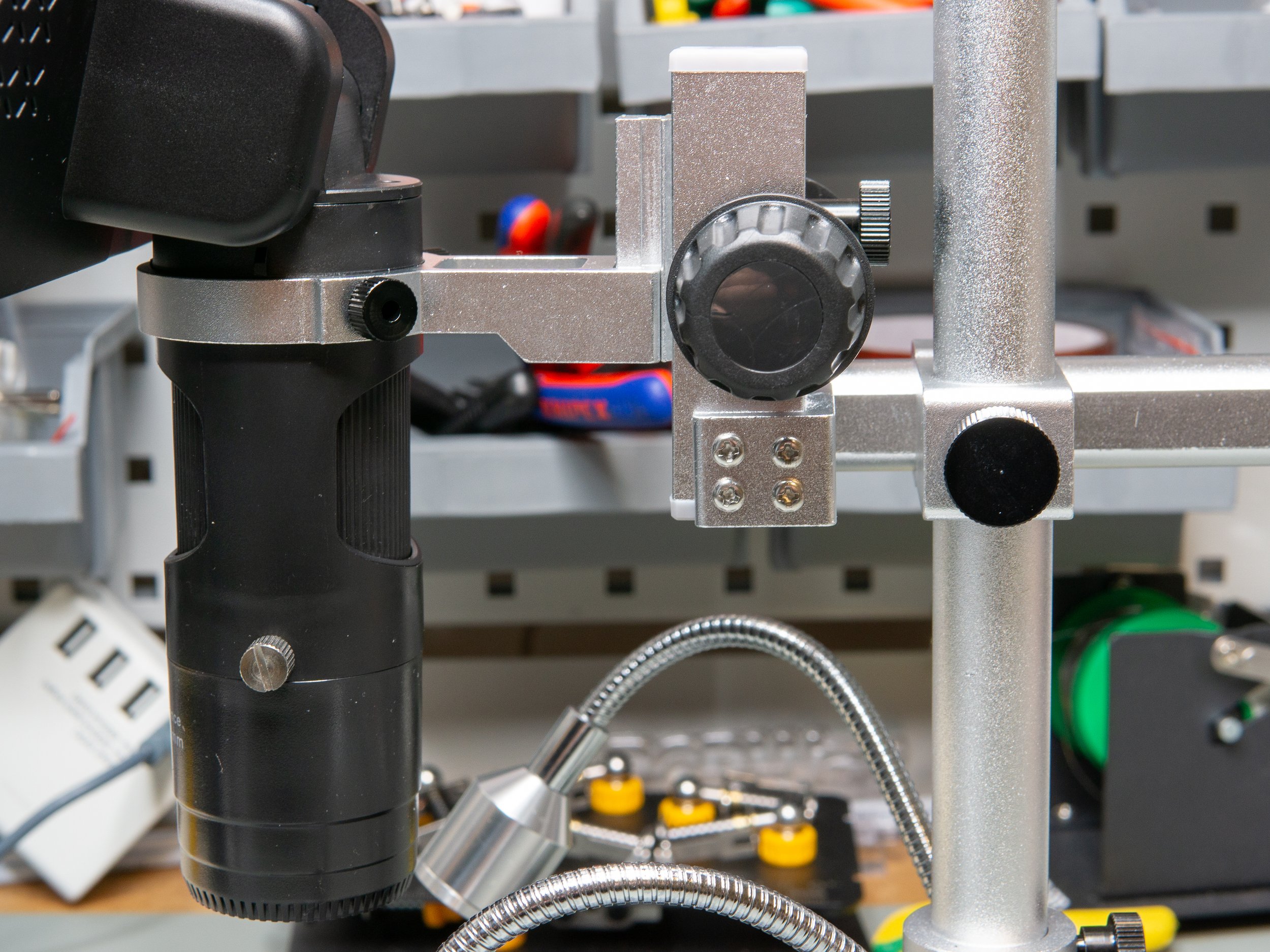
The microscope comes with a nice stand. The stand consists of several parts. First, there is a large (18 cm X 20 cm) base plate. This base plate holds the main Z rod for mounting the microscope. It also accommodates the two LED lights with flexible arms, and two holes on the top of the plate that allow us to mount spring-loaded clips that can be used to firmly hold flat specimens. There is a little DC jack plug at the back of the plate which is the power connector for the two LED lights. The Z rod holds the arm for mounting the microscope (display unit). The arm can be placed anywhere along this Z rod which is helpful when we want to adjust the working distance of the microscope. Furthermore, the arm allows us to move the microscope along the Z-axis (let’s call this coarse focus) and it can also be adjusted along the Y-axis (the microscope moves towards the user or away from the user). At the end of the arm, there is a ring with a notch and two set screws that allow the user to precisely mount and align the microscope.
So far, the only thing I found a bit difficult is that I could not figure out how to adjust the tilt of the Z rod. It was slightly off, so the focusing was not perfect because the surface and the CCD were not parallel. I tried to adjust the hex nut, but I could not move it.
The stand with everything mounted on is relatively stable, but due to the construction, small vibrations can be present, especially when focusing. I also noticed that the focusing ring on the optics is a tiny bit too high up and sometimes I bumped my wrist into the bottom edge of the display while moving around. Also, the presence of the light sources can make focusing a bit difficult sometimes if they need to be placed close to the subject. In some cases, especially with lenses “A” and “D”, they have to be moved close to the lens and they can obstruct the way to the focusing ring.
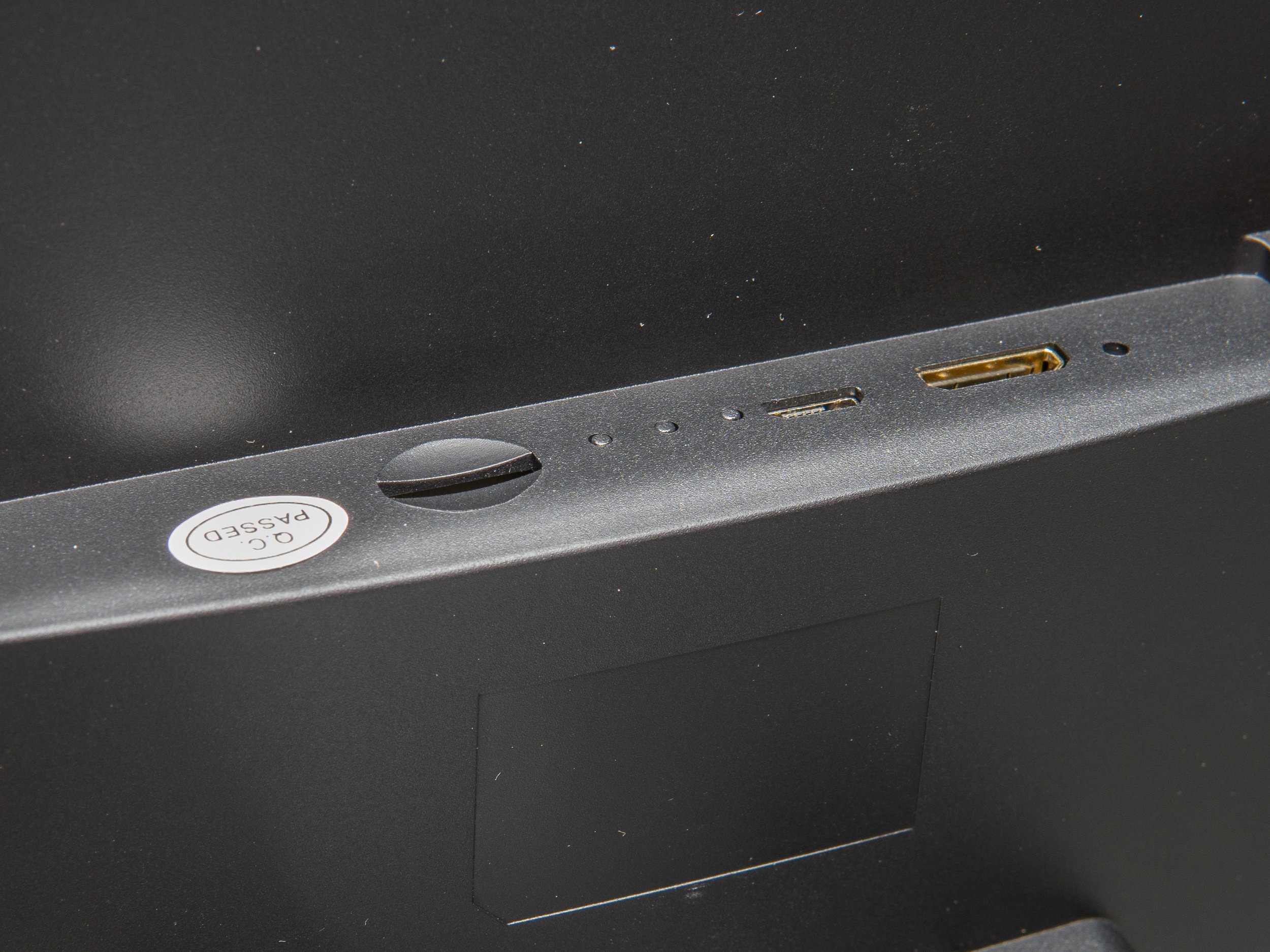
We also get a bunch of cables both for powering the device and for transferring the image of the microscope to another display (i.e. HDMI cable). There is one USB cable which is only used for powering the display or connecting it to the computer, but then there is another 4-way cable in the package. This 4-way cable has a USB-A connector that goes to the power supply (phone charger-looking 5 V, 2 A wall adapter), and then one cable goes to the base plate to power the LED lights, another cable goes to the display, and the fourth branch of the wire ends in a remote controller for the LED lights. Smart cable, and kudos to them that they paid attention to details by making the supply cable much longer than the rest of the cables.
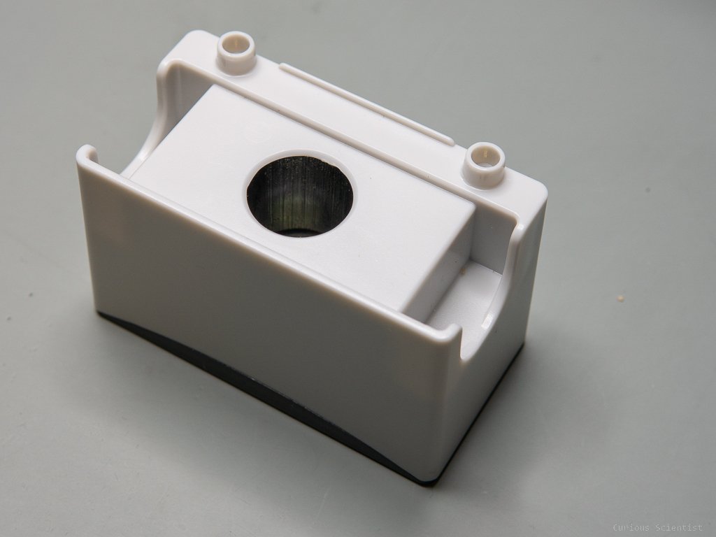
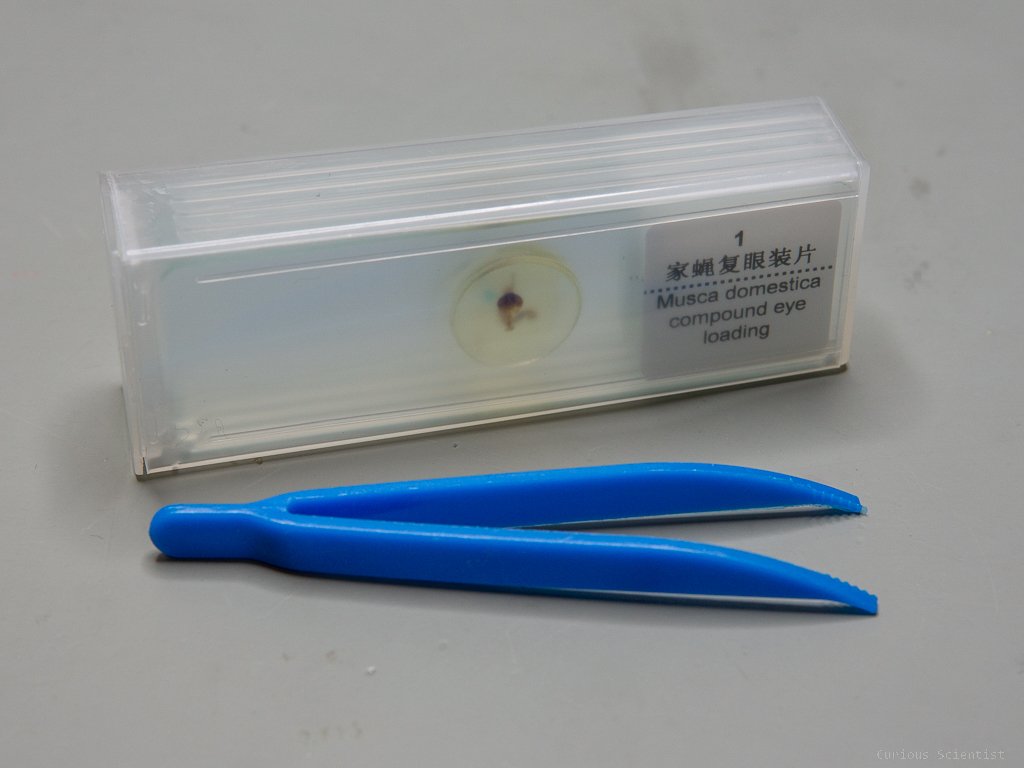
We get another attachment which is a small plastic box with an LED light source in it. This is good when we want to look at cross-sections in “transmission mode”. When this box is used, the power cable has to be plugged into it. It has the same DC barrel jack connector as the LED lights on the base plate. To make this attachment more fun and interesting, LINKMICRO provides 5 samples together with the microscope. They are different cross-sections of carefully prepared specimens mounted on glass plates.
Then, finally, the most important detail is that the microscope comes with three lenses. These lenses have different focal and working distances and they provide different magnifications.
Lens A: “Object distance 12-320 mm”
Lens D: “Object distance 4-5 mm”
Lens L: “Object distance 90-300 mm”

The assembled microscope

4-way cable for power and controlling the LED lights


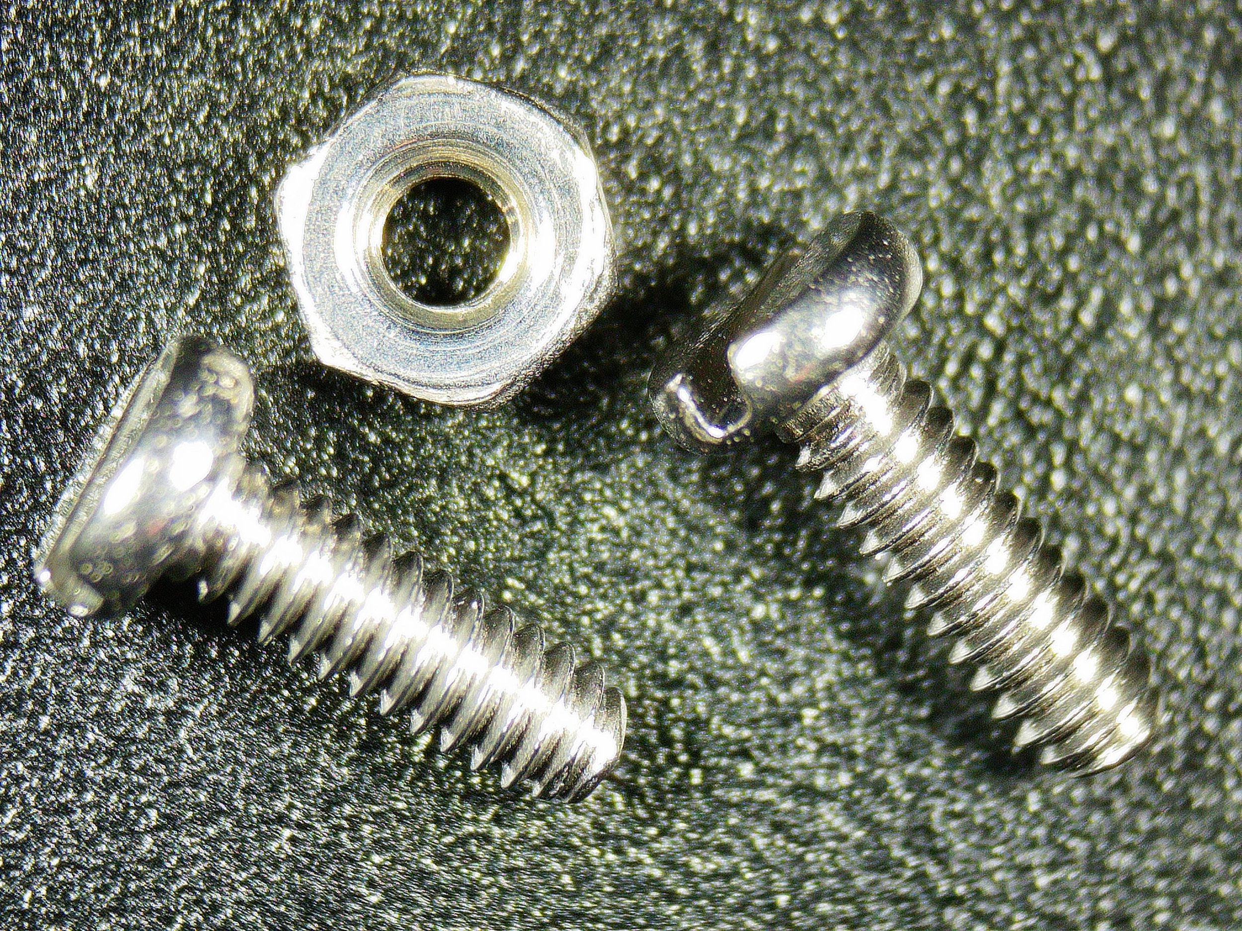
Lens A has 18x up to 720x magnification*. It is good for observing tiny parts. I personally would use them to check the soldering of SMD parts, where the legs are very close to each other and there is a chance to form bridges by bad soldering.
Lens D has 1800x up to 2040x magnification*. This is a bit too high magnification for inspecting electronics, however, it is perfect for using the attachment for the slides and looking at transparent specimens. It opens up a whole new world.
Lens L has 60x up to 240x magnification*. This is a perfect all-around lens for PCB assembly. I will use this lens the most. With this lens, I can achieve a good combination of working distance and magnification which allows me to assemble and solder directly under the microscope.
The lenses can be easily exchanged by simply unscrewing two screws and replacing the lens. Each lens has flat sides at the mounting flange which helps to align them correctly. The only thing I miss is a built-in light source in the lens. So far, the LED lights on the stand are sufficient, but sometimes I wish it had a light coming directly from above the observed specimen.
*Side note regarding the magnification. They depend on the used display size and the applied digital zoom (cropping). Therefore, it is not a good idea to directly compare these numbers to, for example, a professional metallurgical microscope!
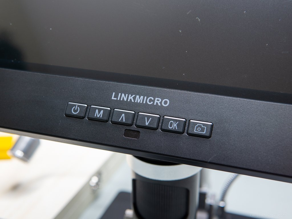
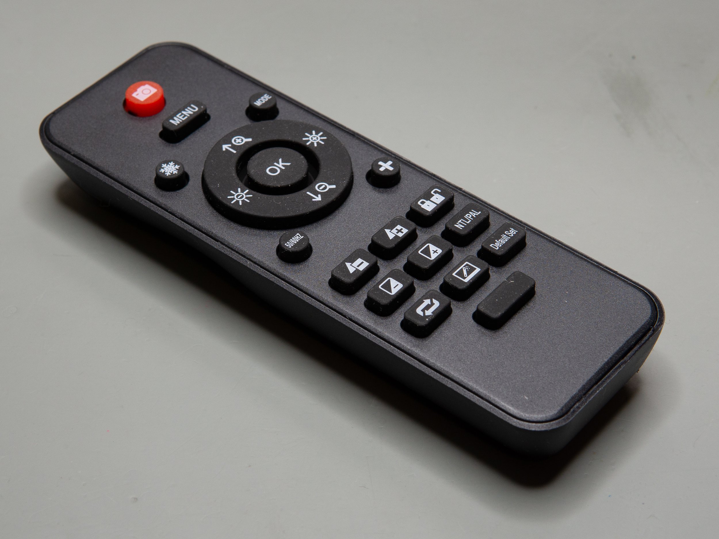
Furthermore, we get an infrared remote controller for the display, too. I really like it because I do not need to touch the display (vibrations) if I want to change some settings on it. It allows to quickly change between photo and video modes, take pictures or start recording videos, change exposure (EV), and adjust further settings.
Finally, a 32 GB micro SD card is also provided with the microscope. It can store a large amount of footage.
The microscope can be connected to the computer via USB. Upon starting the microscope we can choose USB mass storage or PC camera. When selecting the first option, the microscope will act as a card reader and we can open the SD card and read its contents. In PC camera mode, we can use the microscope as a USB camera. Windows automatically recognizes it. In fact, I could directly stream the image of the camera to OBS. This is very good because if I want to show something under the microscope while I also want to show something on the computer, I can record multiple sources at the same time. Also, there is a software provided by LINKMICRO. It is a bit difficult to use it in the beginning because it is not very intuitive, but once you get the hang of it, it is fine. It has drawing tools that can be calibrated, so it can be used for measuring objects.
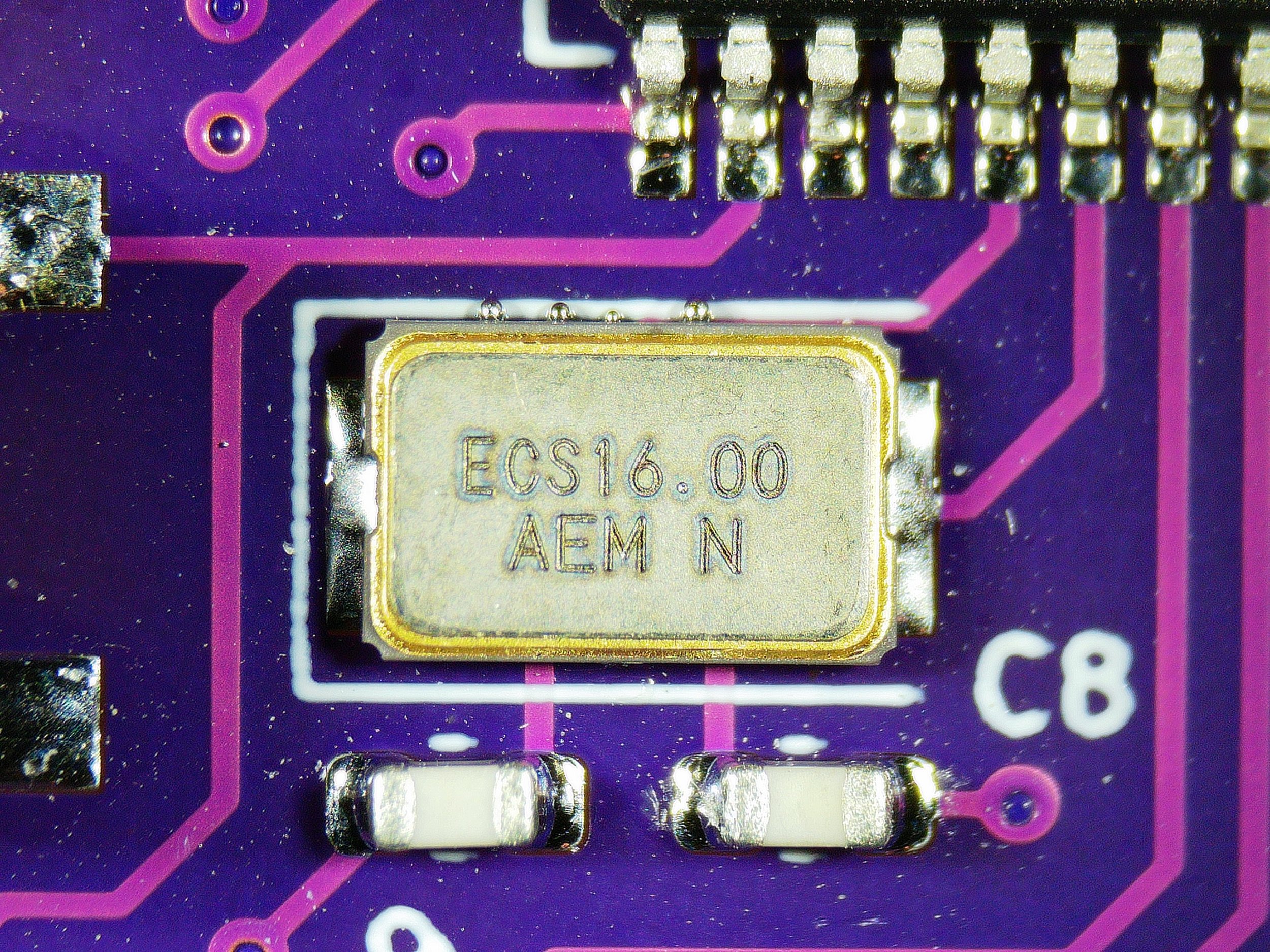
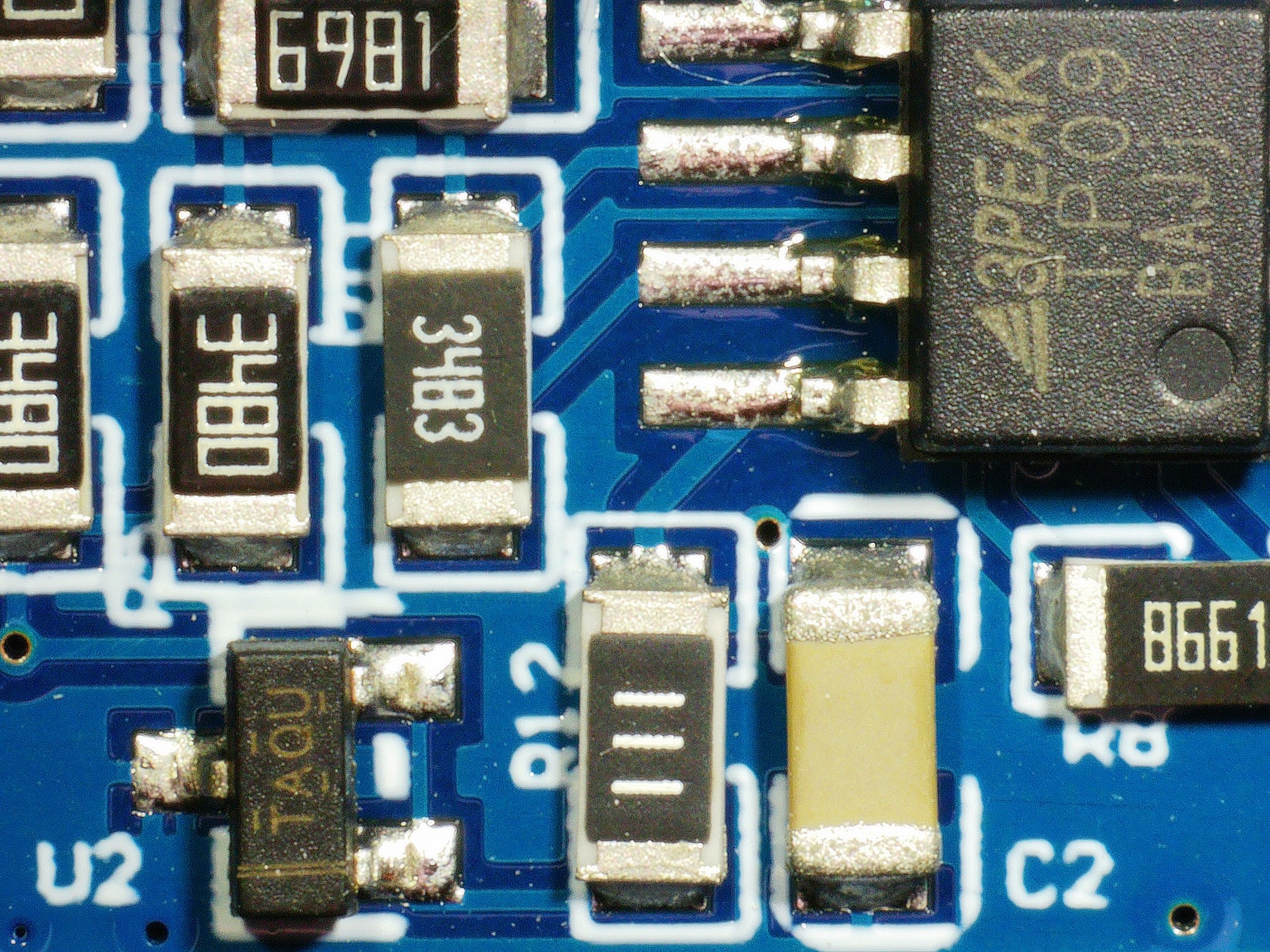
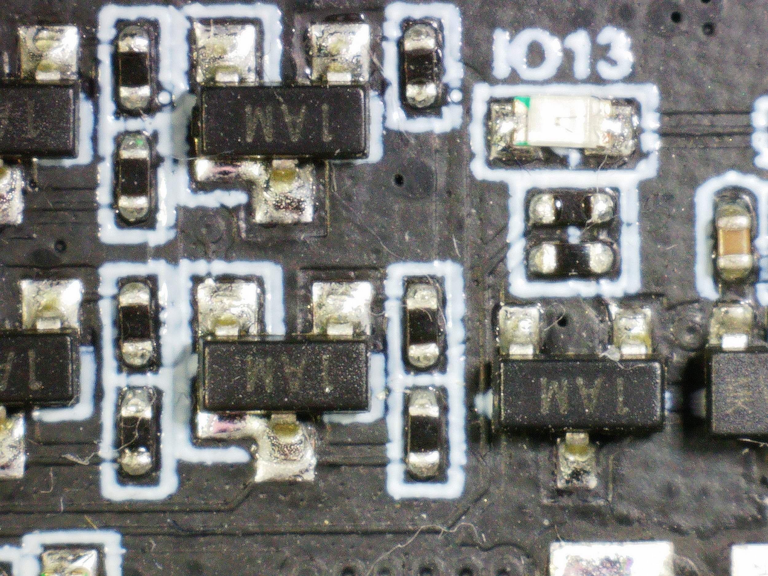
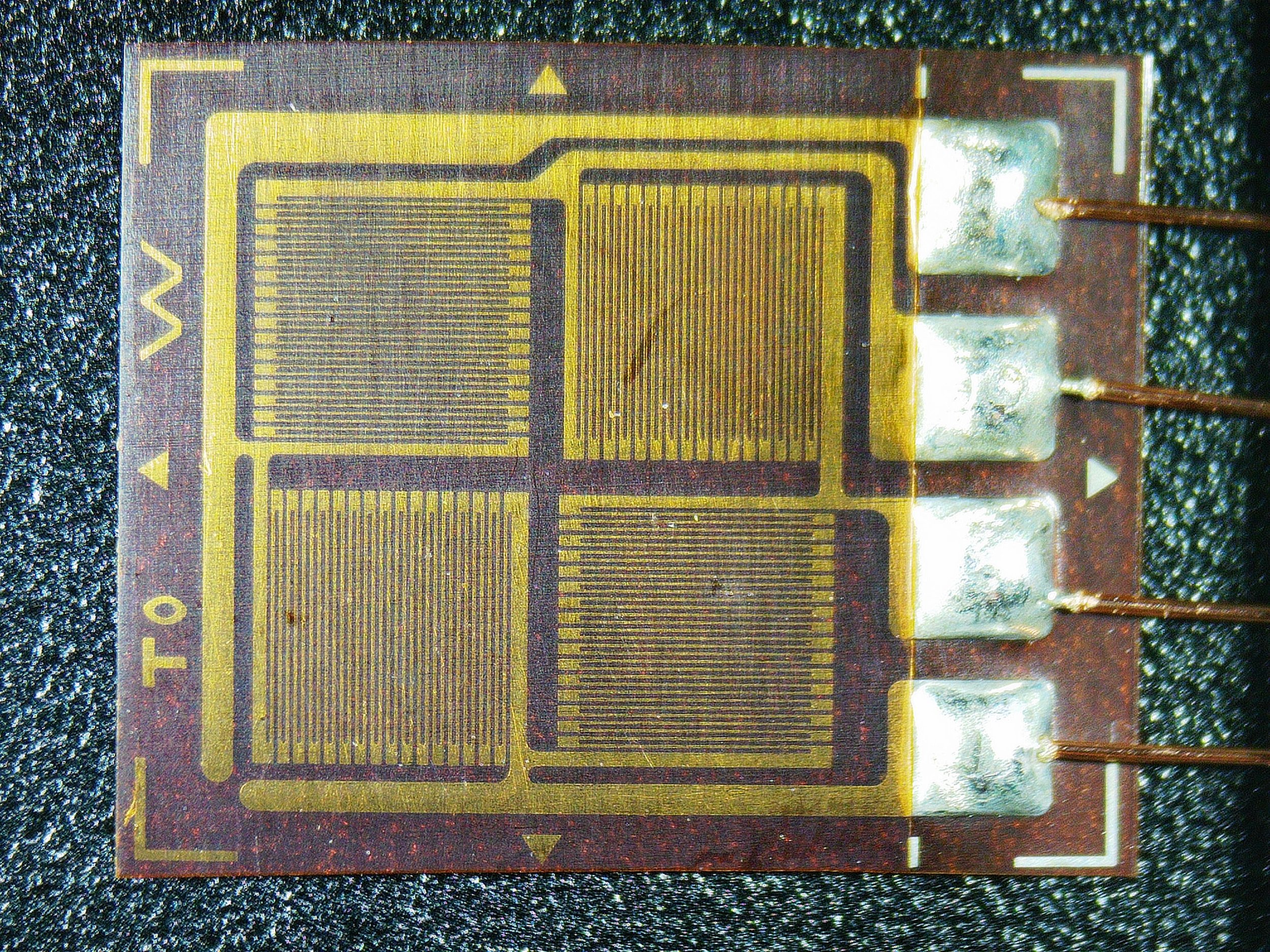
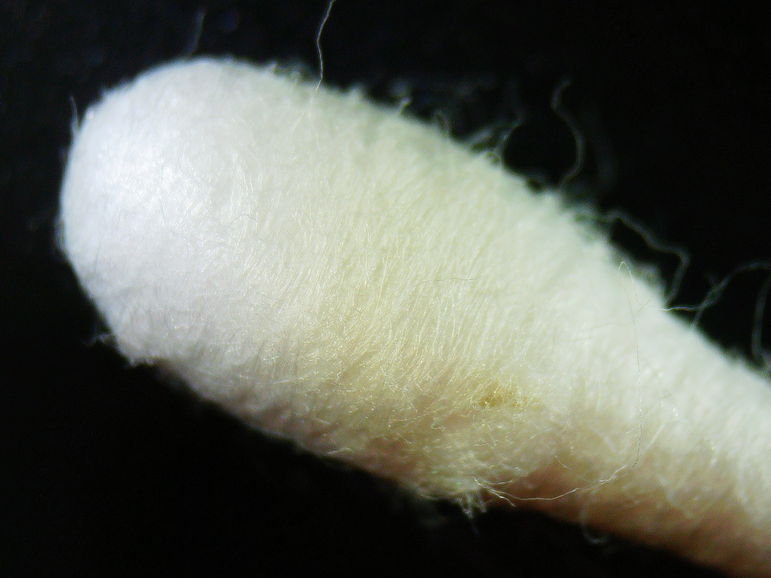
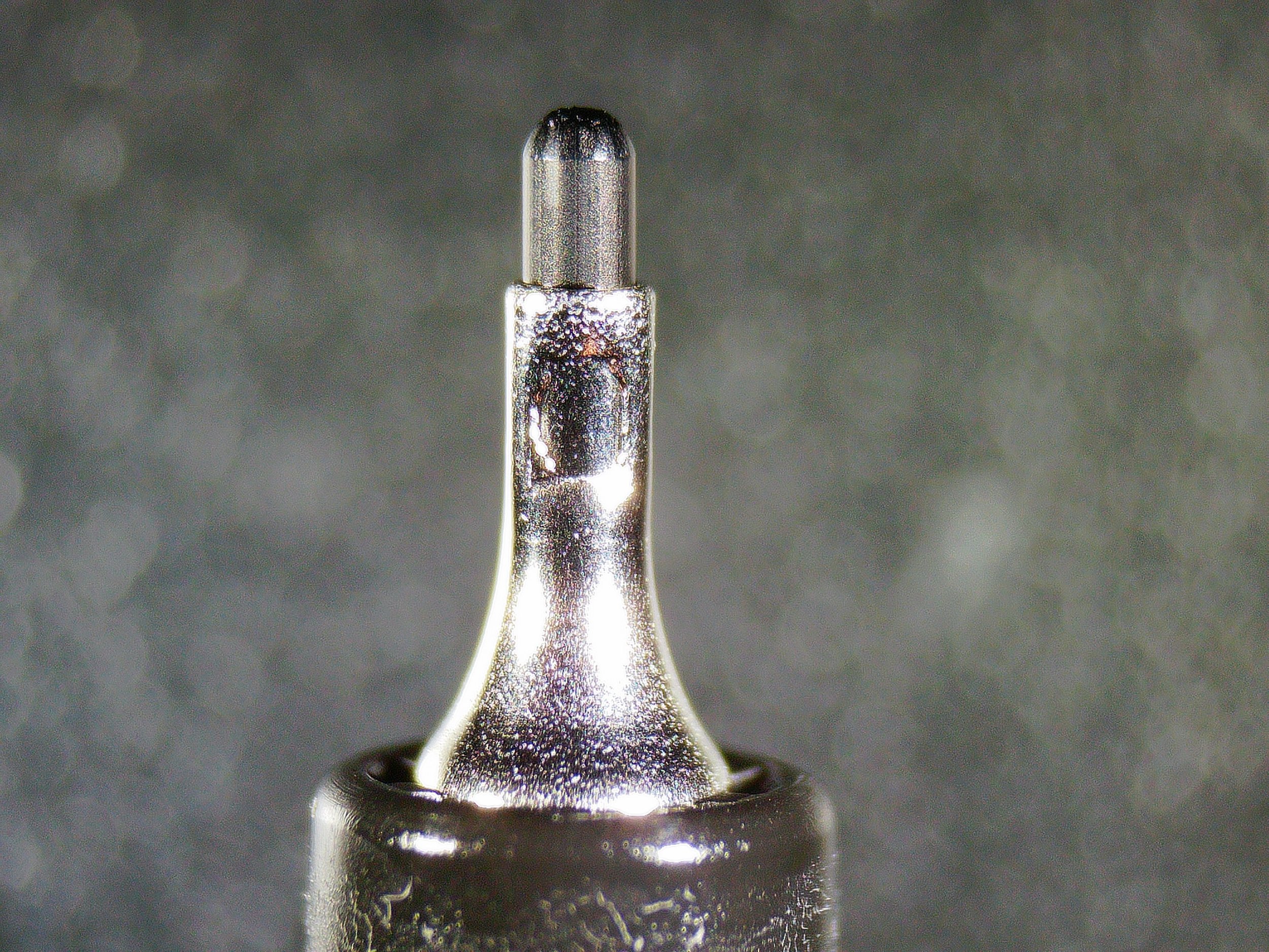
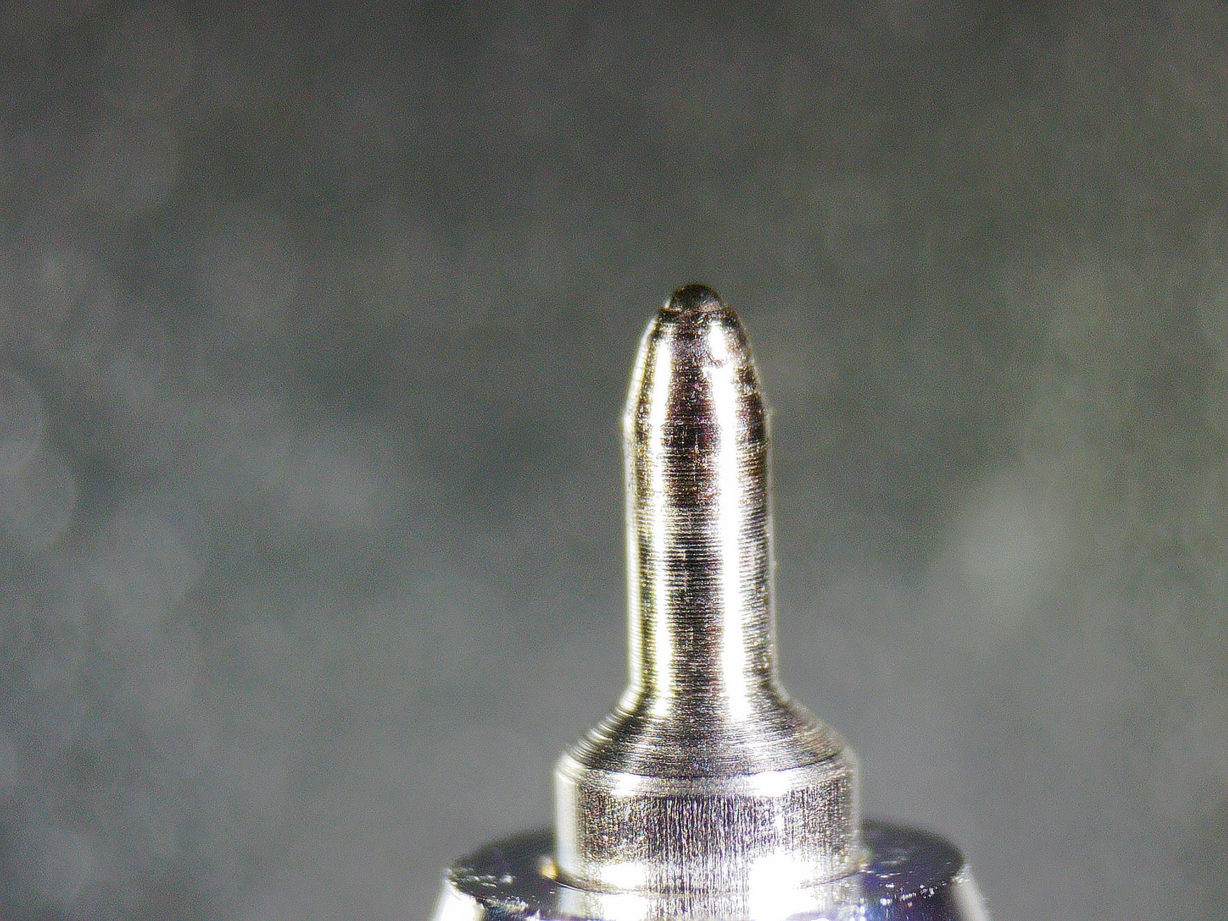
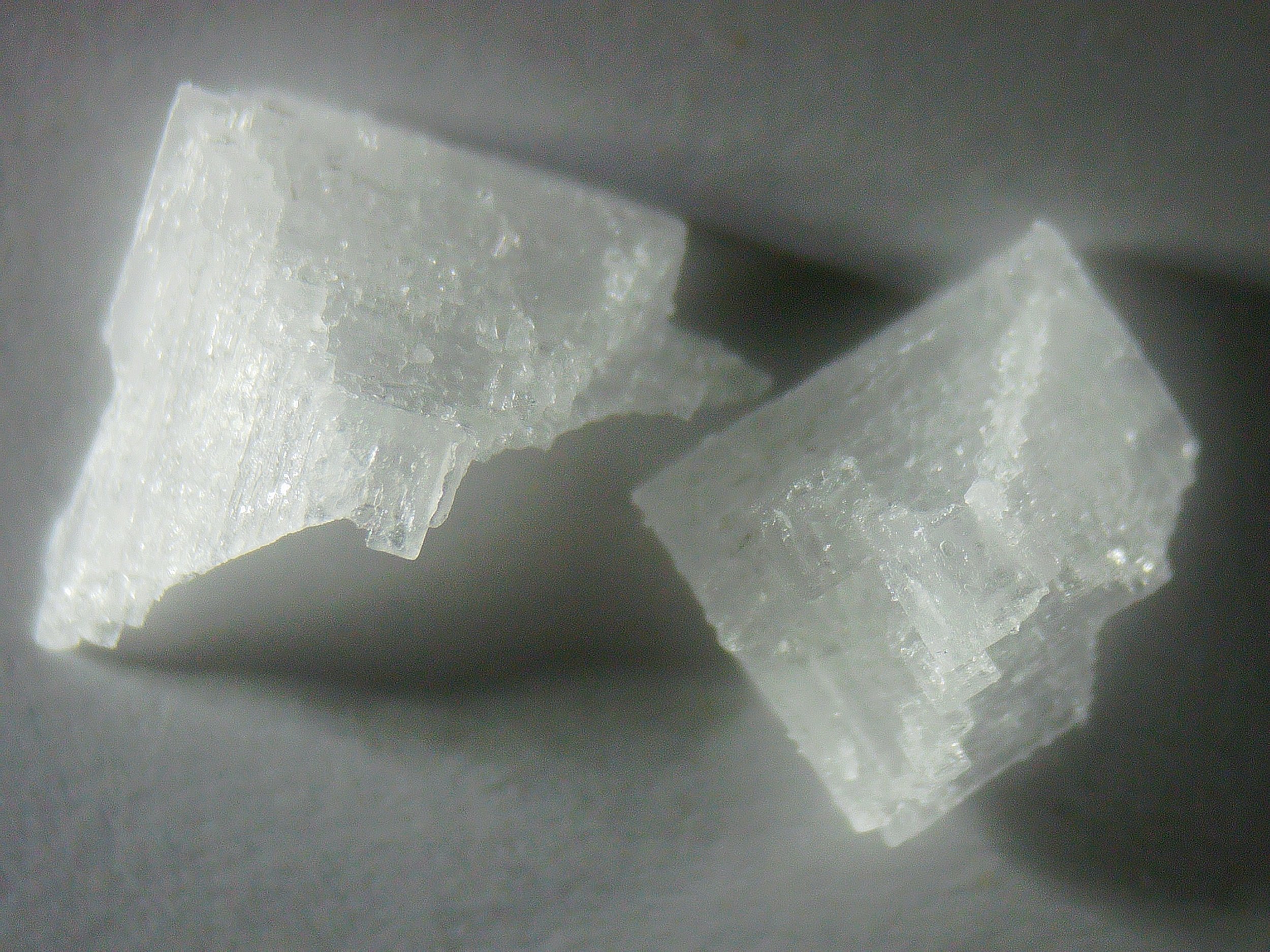
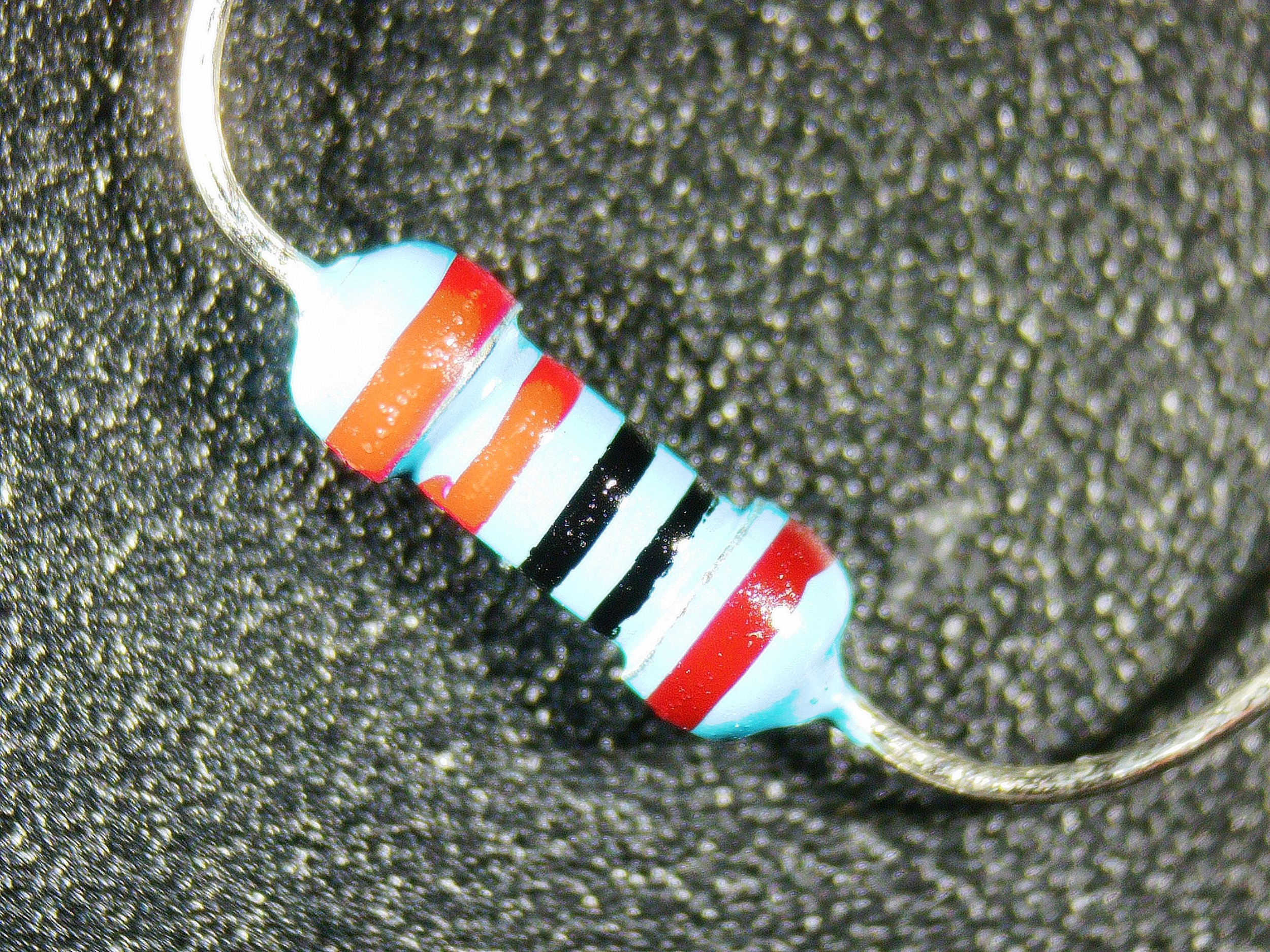
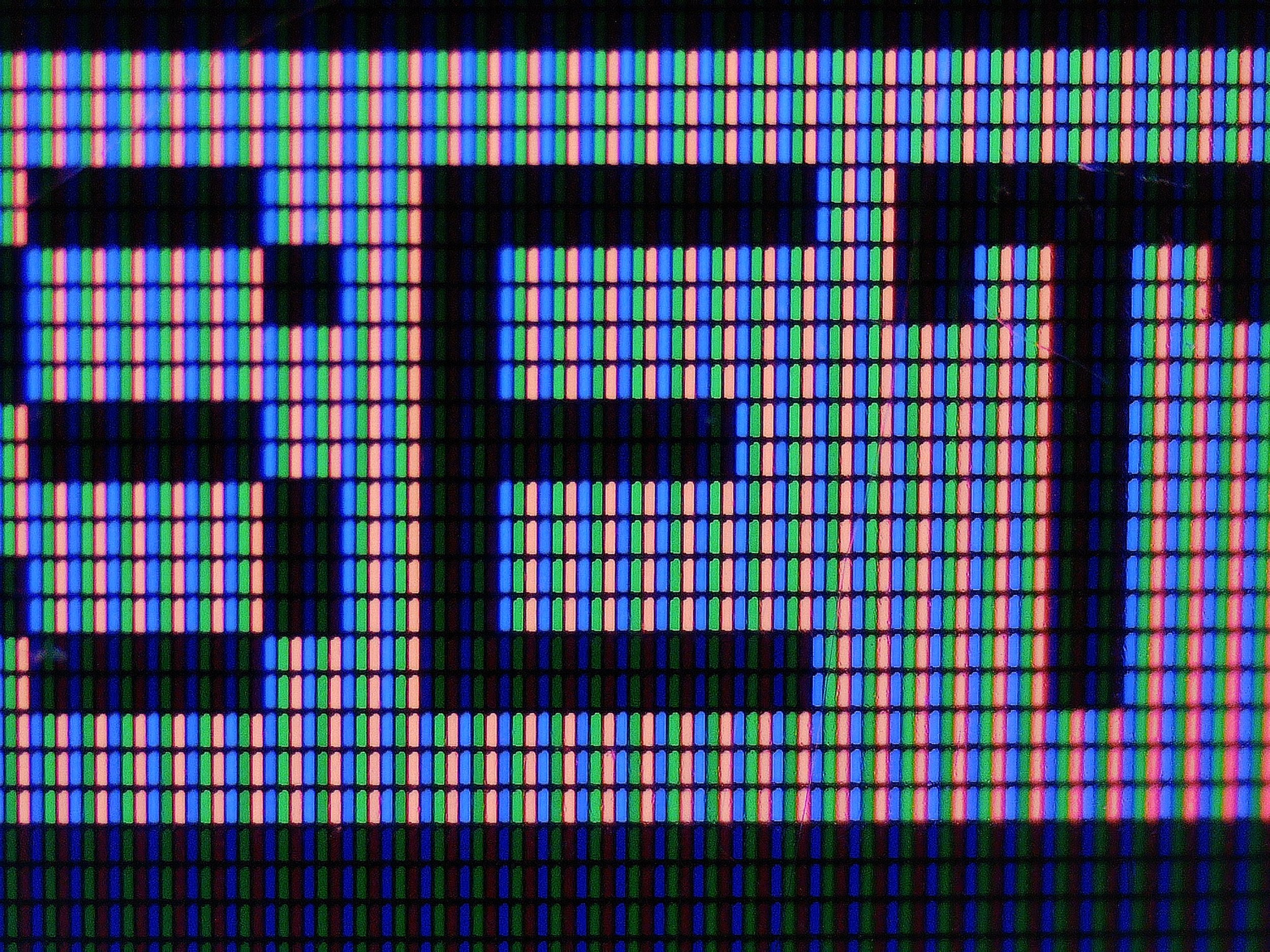
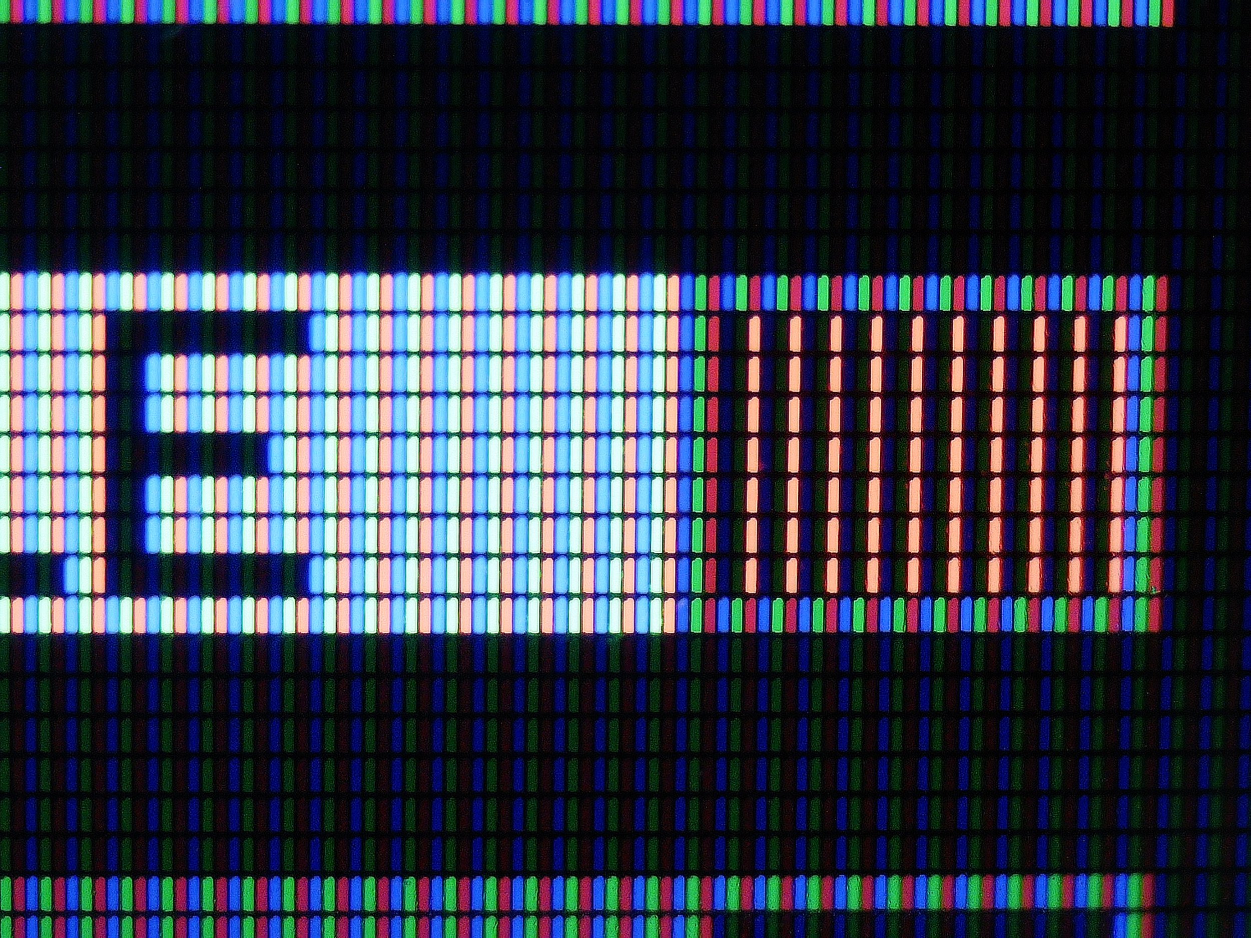
Gallery of images taken with the microscope


Conclusions
This is a fantastic microscope! It has all the features that are needed to be able to carry out PCB assembly, or fault inspection on electrical circuits or similar tasks. The exchangeable lenses make it even better and its large and sharp display makes the work easy.
In more detail:
It was easy to set it up. The instructions that came with the microscope were simple and intuitive.
The microscope is easy to use, especially with the remote controller.
The image quality is good. Both the sensor and the optics seem to provide a reasonable-quality image. Plus the 10” display is great!
It is packed with extra functions (Additional HDMI port, WiFi, USB).
The “Lens L” is super versatile. The large working distance makes it perfect for working with electronics. I can use tools under the microscope or even put a soldering stating under the lenses.
However, I would mention a few things I did not like:
The light source could’ve been built into the lens. (Next version, maybe?) Sometimes, based on the lens (A or D) used and the placement of the light sources, it was hard to use the focusing ring.
The stand (Z column) could’ve been a bit more sturdy to avoid vibrations. Also, it was hard to make it stand perfectly vertically.
PC Software could be more intuitive or it should come with better documentation.
Join my YouTube membership!

“Lens A” focused on the specimen which is sitting on top of a miniature soldering (reflow) station. There is an adequate space between the lens and the object. Safe for work and safe for the microscope, too.