DWIN Displays - Dial indicators and knobs
In this article I show you how to set up dial indicators on your DWIN display. These are useful modules if you want to visualize speed, temperature, pressure or basically anything in a cool way. Dial indicators often look great as part of a weather station, or similar things.
Setting up the display
First, we start with the image editor software because it is important to draw the page properly. We also draw two dial indicators because they can be used both ways: as an input where the user can turn it as a knob, and as an output where the user can read the value of some variable on the dial.
As a first dial indicator project, I recommend overdoing the drawing a little bit so you can quickly understand how the indicator works.
Before jumping to the actual background image I will use in this example, let’s see how DWIN treats the rotation. I drew a little guide that you can follow on the right side.
The angle swept by the needle of the indicator covers the full circle (0°-360°), but when you define the angles in DGUS, you have to multiply the real angle by two because DWIN uses 0.5 as the unit of a degree. So in DWIN’s own system, a circle goes from 0° to 720°.
Thus, in our example, the 45° angle is 90° in DWIN’s own system. And for example, 190° will be 380° in DWIN’s own system.
It is probably obvious, but the rotation direction is clockwise.

Coordinate system of the dial indicator. The 0° starts at the top of the circle and the angle increases in the clockwise direction. Keep in mind that the real angle and the “DWIN angle” has differ by a factor of two. When you enter the angle in DGUS, you have to multiply the real angle by 2. DWIN uses a unit of 0.5°.
Here you can see the indicators I made. I did not include the needles in the image because they are actually separate things. I will explain it in the coming sections.
The top indicator will show us the received values coming from an Arduino. As you can see, the range is between 0 and 5000. I haven’t written the unit on the scale to avoid making it cluttered, but it is milliVolts. It is simply the output voltage of a 10k potentiometer connected to one of the analogue inputs of an Arduino. So, the range is simply 0-5 V (or 0-5000 mV). I also added a box where the received value is printed.
The bottom dial acts as a knob. You can sweep the area between 0-5000 (or just poke somewhere) and send the corresponding value to the serial port. In our case, an Arduino will grab the value and it will print it on the computer’s serial terminal.
The dials are divided into six, 45° sectors. So, in real angles, the needle can cover 270° which is 440° in DWIN’s own system. The zero angle is at 2500 on the dial and at 500, the angle is 135° (270°). This position is the end position of the needle. The 0 belongs to 225° (450°) and this is the starting position of the needle. So, the needle of the indicator moves between the 225° (0) and 135° (5000) positions in the clockwise direction. It will never touch the area between 0 and 5000 at the bottom of the circle.
Once you finished designing and drawing your indicator, draw the needle on a new layer. Then save the needle in a separate JPG file (i.e. as “0_dialgauge_indicator.jpg”). When we build the config files, we will need to create a separate icon file (ICL) for the needle and upload it to the display similar to the background image which is saved as “32.ICL”.

Background image with two dial indicators
Let’s start with the top dial indicator which will show the received values. I mentioned earlier that you need to save the needle as a separate jpg file. First, open the DWIN ICL Generator under the Welcome tab, and load the needle’s picture in the same way as you loaded the background picture. Then generate the ICL file as usual, and save it as “44.ICL”.
Once you have the needle saved as an ICL file, go back to the Touch and display config tab and add the Icon Rotating field under the ICON Display menu to your dial gauge. Do it in the same way as you see it in my picture. The squares’s top left corner should be at the centre of the indicator where the needle begins, and the length of the sides are the same as the radius of the indicator.
Then, under the parameters, pick a VP address. I picked 0x1000. Then under the Icon file drop-down list, you should see the 44.ICL as an option. Select it, then click the green + icon under it. A new window will pop up. Select the needle and press OK. Another window pops up. Here, you need to select the rotation centre of the needle. This is at the centre of the base (bottom) of the triangle. Click there to have some initial values, then in the ICON Rotation Center parameters, write in the correct value manually. Since you know the dimensions of your image, you can easily determine the centre. The coordinate system is at the top left corner of the image and the positive direction is downwards (Y) and to the right (X). I have an 8x82 image, therefore my centre coordinates are 4 (middle of X) and 82 (bottom of Y).
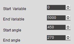
Some of the relevant parameters for the needle
Then we have four parameters which I explained in the previous section. The start and end variables are the real values that we have printed on the dial. In my case 0 and 5000 respectively. Then the start and end angles are defined by the angles at the 0 and 5000 positions. Number 0 sits at 225° real angle which translates into 450° in DWIN angles. Number 5000 sits at 135° real angle which translates into 270° in DWIN angles. The display mode changes between opaque and transparent backgrounds. Choose which is suitable for your image. The filter -if I understood properly- can be used to take away the background from your needle if you have a non-transparent background behind the needle.
The VP mode is set to Int because we are displaying integers. The Initial value can be whatever you choose.
Then we create a data variable display over the received box. It has the same VP address as the indicator next to it because we want to see the exact value at the tip of the needle. The variable type is Int (2 bytes) and we want to display 4 integer digits. The rest of the parameters are not relevant, or you can adjust them (for example font colour and size) according to your requirements.
Now you know how to add the needle to the display and the data field over the boxes, so repeat the exact same steps for the bottom indicator. The only difference is that you need to use a different VP address, for example, 0x2000.

Some of the relevant parameters for the rotation adjustment (knob)
Since the bottom dial indicator also acts as an input field (knob), we need to add another control over the whole indicator. In my example, you can see a yellow rectangle that covers the entire indicator. Go to Touch Control and add a Rotation Adjustment field over the indicator. Set the VP address to 0x200. The data format is 0x00 (integer) since we want to select integers by moving the indicator. Then press the Set button under the Center coordinate text and select the centre of the dial indicator at the bottom. This is why I suggested drawing a tiny circle at the centre so you can easily find it. If you really want to do a perfect job, you can get the exact coordinates in your image editing software where you created the picture and write it in manually. The inner and outer diameters are up to you. These two values define a ring over the circle of the indicator where the display is sensitive to touch. The inner diameter is the distance along the Y-axis measured from the centre of the display until the beginning of the ring. In my case, the centre is located at 652 pixels and the inner diameter is set to 65. The outer diameter is basically the radius of the indicator (125 pixels in my case). Then the start and end angles and their return values are defined according to the same principles we used for the needles.

Display with all the fields
Join my YouTube membership!

Buy the display using my affiliate link!