Precise focus stacking device for macro photography
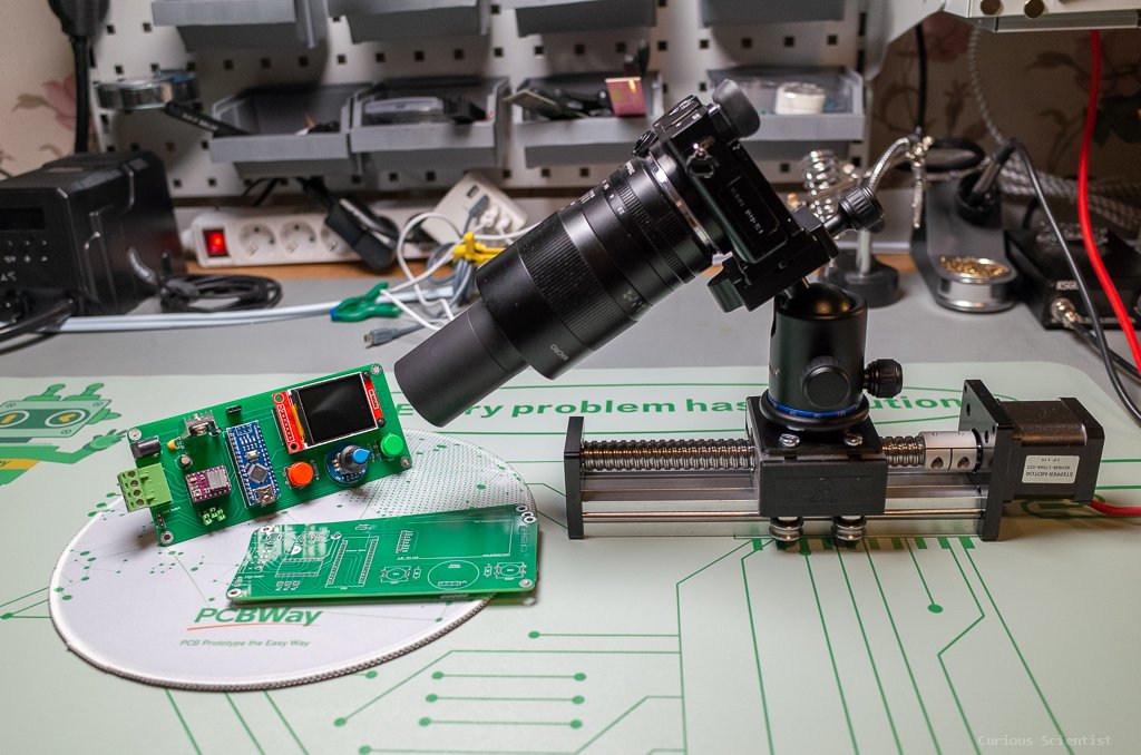
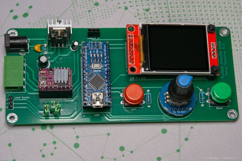
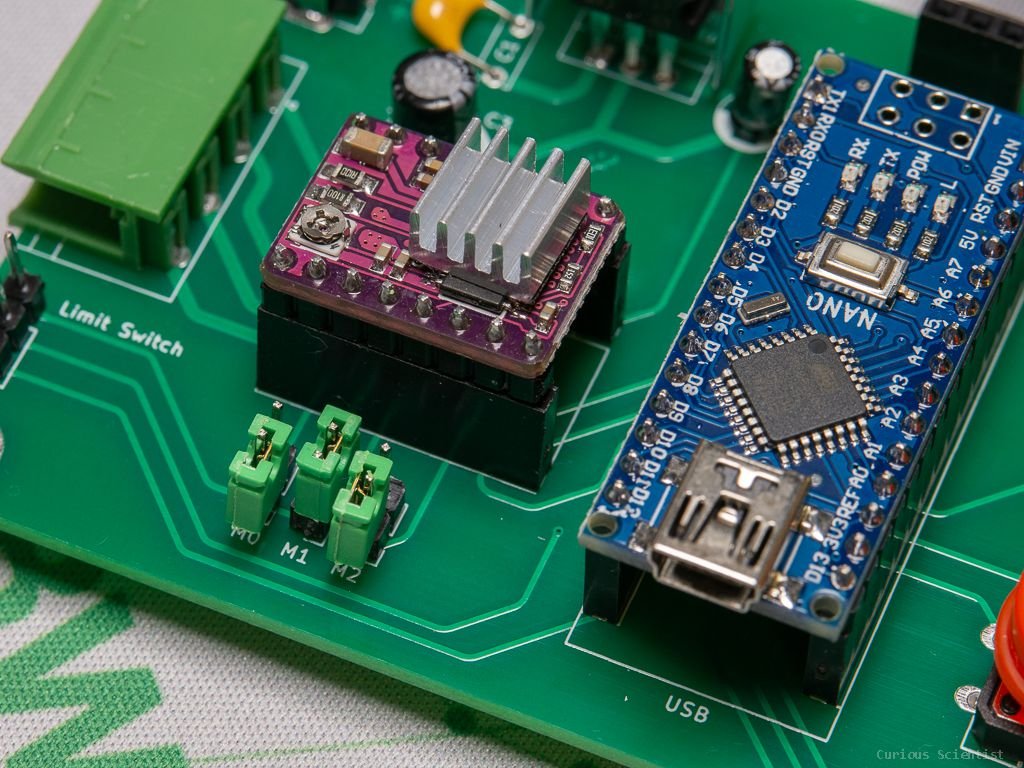
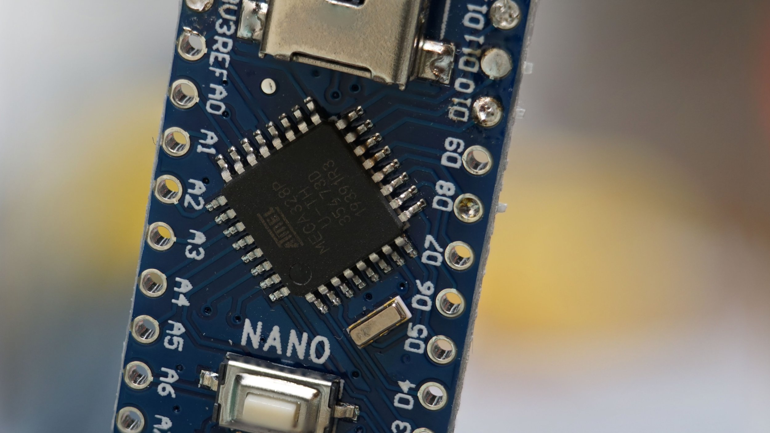
In this video, I show you my new little device which is used for making spectacular macro photos. The device consists of a stepper motor-based linear actuator, a stepper motor driver, a display, an Arduino Nano and some auxiliary parts to make everything work properly. As you might know, macro photography is challenging, especially if you want to take pictures of very tiny things. The issue is that at these levels, the depth of field (DOF) becomes very shallow, which means that only a tiny part of the picture will be sharp and the rest of it will be blurred and out of focus. The solution for this issue is to scan across the whole subject, take pictures of all the details, and then in a suitable software, blend these partially focused images of different parts of the subject into one single image where the whole subject is sharp.
Of course, this could be done manually, by putting the camera on a rail with an adjusting mechanism and moving the camera, then taking a picture every fraction of a millimeter, but when you need to take hundreds of pictures, it is just too time consuming.
Therefore, I tackled this challenge in this project video and I came up with a system that does everything fully automated.
Working principles
The working principle of this circuit is that one can program the necessary parameters, and then the circuit will drive a stepper motor (linear actuator) and trigger the shutter of a camera (it is tested for Sony A6000). Since this specific application focuses on macro photography, we can decide whether we put the camera on the linear actuator, or the object (e.g. a bug) itself. Then, by moving the linear actuator and taking pictures we get the pictures for the focus stacking. Finally, we just need a software to compile the set of images into one single picture.
The code I developed works in the following way:
Upon startup, the user can do a homing or can skip it
The user has to enter the chosen aperture (f-number, written on the lens)
The user has to enter the chosen magnification (can be read from the lens if it is a macro lens, or can be calculated)
The code calculates the depth of field (DOF) and suggests a step size (DOF/2) for the stacking
The user can optionally override the suggested step size with a unique value
The user has to move the carriage to the desired finish point, the point where the last picture is taken for the stack
The user has to move the carriage to the starting point. The carriage will move from this point back to the finish point. This point is where the stacking starts
The user has to start the stacking (GO!)
Once the parameters are set, the code automatically recalculates the necessary parameters. For example, if you change the f-number, the DOF and step size are automatically recalculated. If you change the starting point or finishing point, the travel distance and the number of steps are automatically recalculated.
After the stacking is initiated, the progress can be followed on the display. After a picture is taken, the progress is updated on the display. As the code proceeds further, more and more pictures will be taken and at the end, the number in the "progress" box will be equal to the number in the "number of steps" box.

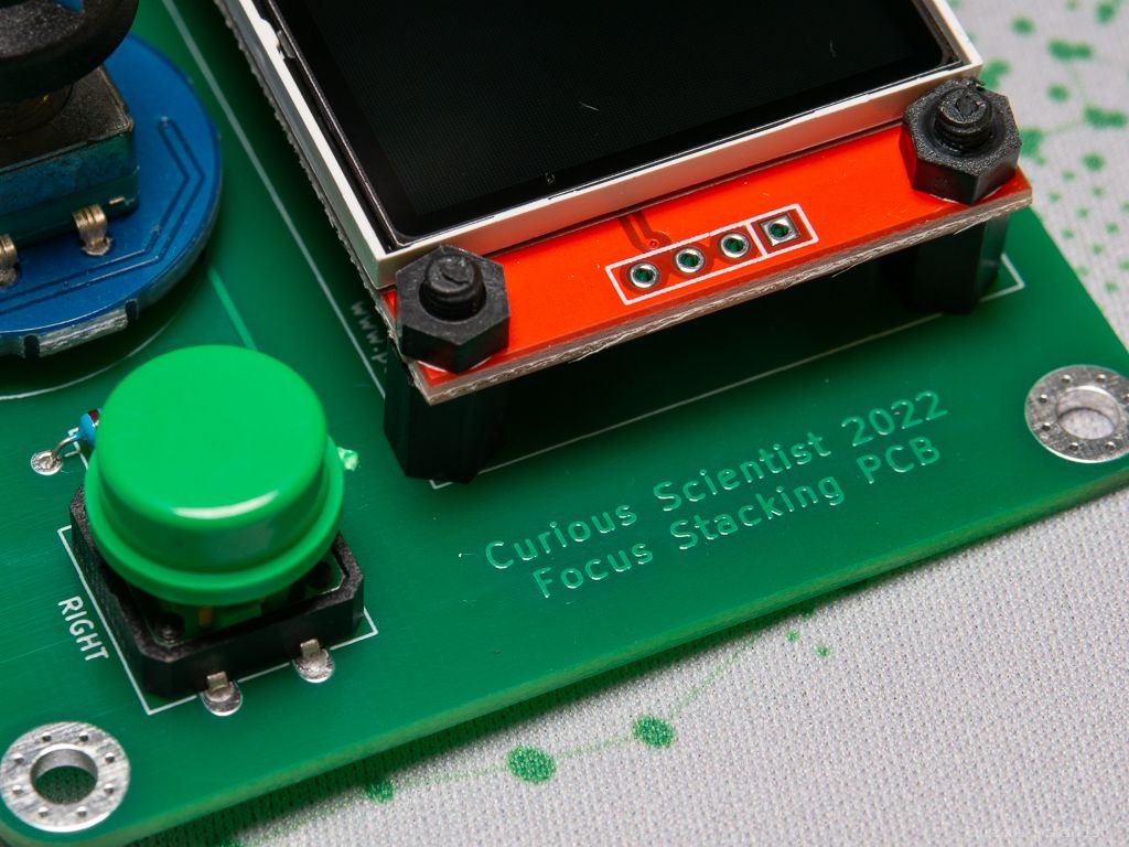
The display where everything can be adjusted. Cyan fields can be modified by the user, green fields are fixed because they are filled in with the calculations’ results. The position in the menu is indicated by a red square and when a menu item is selected/active, the red square becomes green.
A good resource for learning about the calculations can be found under this link.
Some extra pictures of the device and some macro shots
Join my YouTube membership!
Buy my PCB from PCBWay!
