Full-frame digital camera from scratch - Part 1
Recently I published some projects where I introduced the TCD1304 linear CCD. First, I just simply showed how to drive it, and then I used this knowledge to build a spectrometer. In some videos, I hinted that I will use this CCD in more projects. Well, this is one of those projects.
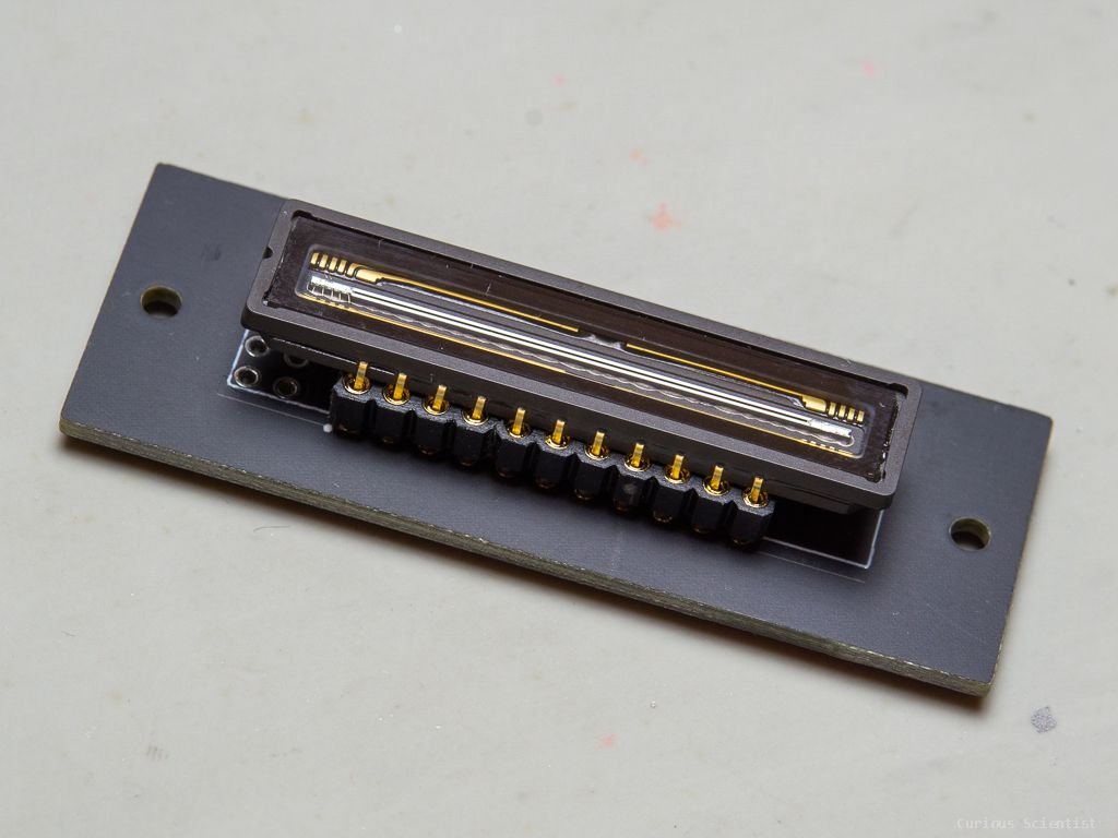
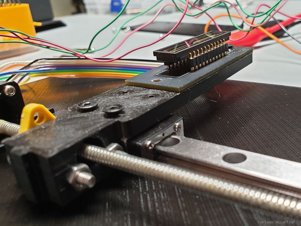
My custom miniature TCD1304 PCB with driving and signal conditioning circuit.
So, this TCD1304 linear CCD has 3648 pixels and each pixel is 8 um wide and 200 um high. The distance between the centre of two adjacent pixels is 8 um. Counting up to 3648, this gives us 29184 um or ~29.1 mm total sensitive length.
This is great news for us! Why? If we take a full-frame camera, we know that the dimensions of the frame (sensor or film) are 24 mm (height) x 35 mm (width). This means that we can cover the height of a full-frame image with our sensor which is more than 29 mm long. Of course, we lose that 5 mm additional sensor area, but it is not a big deal for now. Still, there is that 35 mm width that we need to take care of somehow. Remember, a pixel is 8 um x 200 um, where 8 um is now in the vertical direction and 200 um in the horizontal direction. So, all we need to do is to horizontally move the linear CCD along the width of the frame and capture the image. Simple.
This leads us to the idea of scanning the image plane with the TCD1304. Vertically, we have a fixed resolution which is defined by the 8 um pixel width, but horizontally we need to think a little bit. In the early iterations, I tried a miniature linear guide with a built-in stepper motor. It worked, but it was not the best because the motor was constantly overheating. Since most of the parts I used are 3d-printed PLA, I could not really allow any hot parts because it would undermine the rigidity and structural integrity of the structure. Also, the construction I first built was a pure proof-of-concept structure. It was based on some 3d printed sliding carriage. It worked, but it was a bit wonky and it had some slack. Still, I could take semi-decent images with it. The stepper motor I used could do 20 steps per turn and one turn moved the carriage by 500 um (0.5 mm screw pitch). This means that 1 step was 500 um / 20 = 25 um. To cover 35 mm with 25 um steps we can create 35000 um / 25 um = 1400 pixels. This would be the horizontal resolution. Using “x2” or “x4” microstepping we can boost the horizontal resolution to 2800 or 5200 pixels.

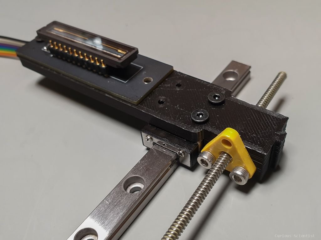
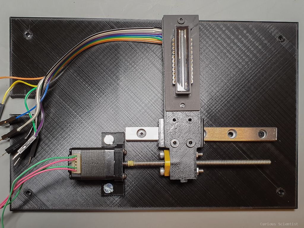
Top view of the assembled proof-of-concept build. The CCD was sliding on two 4 mm diameter steel rods. The construction worked and I could get somewhat decent pictures, but I was not satisfied with the overheating motor (yes, I took care of the driving voltage and current).

A little better view from behind. You can see that I have also printed a new plastic “thing” that is attached to the nut on the threaded rod. That plastic piece grabs the CCD holder and drags it with itself.

The miniature linear guide with a stepper motor used for the first attempts. (Affiliate link under Parts&Tools section)
Below you can see one of the first images taken with the above structure. As you can see Buttercup is almost perfectly in focus. Note that the image was taken with a 58 mm lens at f2, so the depth of field is very shallow. Also, the focus was set somewhat arbitrarily, so the image is a little bit soft. You can also observe the black bands at the top and the bottom. They are the parts masked out by the 35 mm x 24 mm frame. Remember, the CCD has 29.1 mm long sensitive area and we only use 24 mm of it, so the top and the bottom bands are roughly 2.5 mm wide each. The image itself is a simple bitmap. Each pixel from the CCD had a value between 0-4095 based on the illumination of the pixel. After scanning the whole frame, I ended up having a large matrix with values between 0-4095. Then I just translated this data into an image and voilá!

One of the first successful images taken by the camera.
Let’s build from the basics!
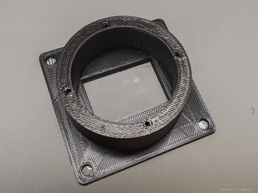
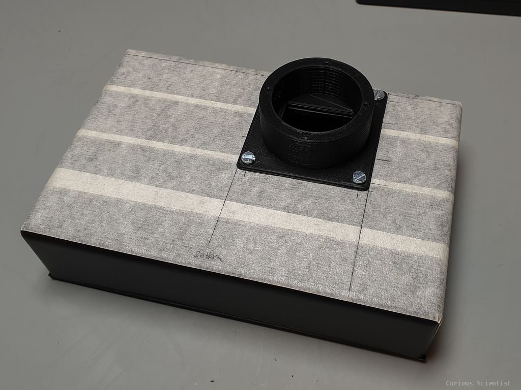
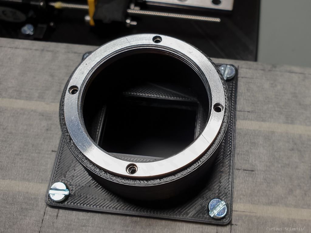
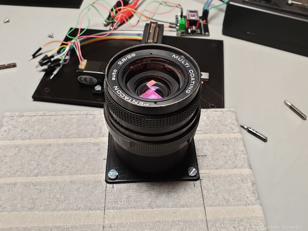
In my opinion, we should start from the lens and then gradually reach the linear CCD. I have a bunch of old M42 lenses, so I will use one of them for this project. I also had an old Zenit-E that I salvaged for this project. The reason why I wanted to start with the lens is that the lens determines the dimensions of the rest of the things (basically, the camera’s dimensions). The most important characteristic of a lens in this project is its flange focal distance. If I really want to simplify it, it is the distance between the mounting flange and the sensor (film or CCD). This property of the lens cannot be changed and one has to be very careful with it. If you have a Nikon DSLR and you tried to mount an M42 lens on it, you learned about this problem the hard way. The Nikon (F-mount) and the M42 have different flange focal distances, and if you directly mount the M42 on the Nikon, you will notice that you cannot focus to infinity (and that the distance scale on the lens is not true anymore). The reason is that the Nikon F-mount has 46.5 mm flange focal distance while the M42 has only 45.46 mm. When the M42 lens is set to focus at infinity, the focused picture from the lens is projected (46.5 mm -45.46 mm =) 1.04 mm in front of the sensor. And this is why an M42-Nikon adapter has to have a (dispersive) glass element in it, to correct for the focus and “project” the light to the sensor properly, making up for that 1.04 mm difference in flange focal distance. To avoid this issue with my build, I was extra cautious and I designed the camera body in a way that the lens is actually a bit closer to the lens than the flange focal distance of the lens. This will render the distance scale on the lens useless, and I will lose some room from the lower end of the focusing distance, but I would rather sacrifice “close-up” shots than the possibility of focusing to infinity. I will want to use the camera outdoors anyway. So, I drew everything in Fusion 360 and I hoped that my prints and assembly will be very close to the designed dimensions.
So, this all looks nice in theory, but how should we solve the challenge?
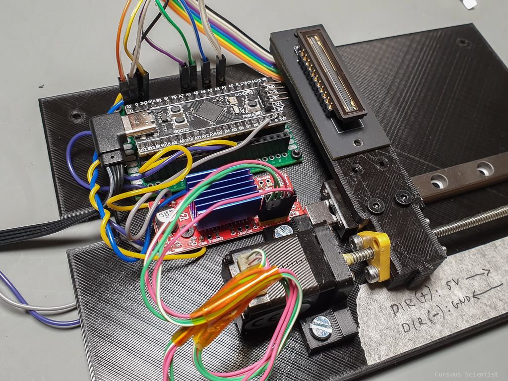
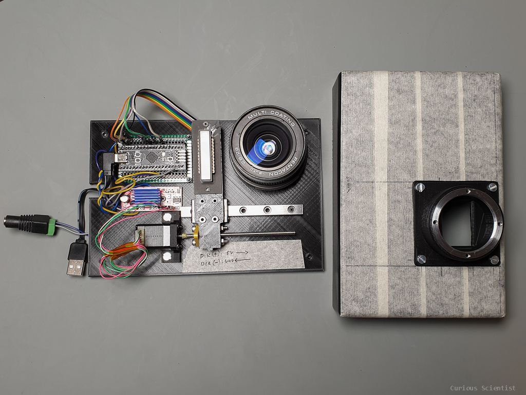
After searching a little on the internet, I came up with another plan to move the CCD. I purchased a NEMA8 motor with a built-in lead screw. Instead of a normal shaft, a 100 mm long lead screw was installed as a shaft. The lead screw has 1 mm lead which means that 1 turn results in 1 mm linear movement of the nut. The nut is just a simple polymer piece, but it is enough for the job. With this more powerful motor, I could install a PCB holder on a rigid miniature linear rail. Before building the structure shown in the gallery, I tried to make a bit different construction using the original stepper motor, but when I tried to move this rail with that stepper motor, it did not have enough power to make the mechanism move...
Now as the new mechanism is assembled, I can focus on explaining a bit more about the operation of the camera. First of all, the CCD can scan the picture from left to right as well as from right to left. At this moment, we just want to go from one side to the other, we don’t care about the scanning direction. The frame for the scanning is 24 mm x 35 mm, but there is a little extra wiggle room for the CCD itself. Since the mechanism is not 100% perfect, I always start scanning a bit before the frame and I finish scanning a few steps after the frame. This is just to make sure that the whole image is captured.
In this version, the scanning is actually very simple. I capture an image (a line) from the CCD, then I make the stepper move 10 steps (50 um), and then I capture a new line again. This step-scan-step sequence goes on until the camera goes through the whole plane. The format of the output data is very simple: each scan is just the result of the AD conversion of the CCD line. So, each pixel is represented by a value between 0-4095 depending on the illumination of the pixel. One line scan is therefore a vector with 3648 elements. As we scan the image we have more and more of these vectors. As of now, I just keep collecting each line scan into a text file which basically becomes a huge matrix at the end of the process. This matrix is now let’s say a 2800 x 3000 matrix where each item is an intensity. Guess what, this is basically a bitmap without all the fancy headers and stuff.
So, I can take this matrix and just plot it as an image where each pixel value is translated into a grayscale intensity. The final result is a black and white picture.
Some extra resources


Join my YouTube membership!
Buy my PCB using the link below:

What’s next?
In the coming videos and articles, I will be focusing on making this proof-of-concept device into a proper camera. I will design a robust enclosure and print it and I will focus on the coding part more.
The following things will be implemented in the future:
Fully closed 3d printed enclosure
Battery-operated mode
Display for controlling the camera and viewing the taken pictures
Exposure button
SD card slot
…etc.