So, as I previously hinted, I wanted to further improve the microscope because I experienced excess vibrations and a lack of stiffness. When I published the previous work, I had already ordered the new parts that are used in this final upgrade. Finally, I achieved a rock-solid microscope with all three of its axes motorised and able to achieve a 1-micrometre step size. With the new Z-axis linear actuator and frame, the hardware is considered finished. I am happy with all the moving parts of the microscope now, and if there are future updates, they will be focused on software-related updates.
Refresher
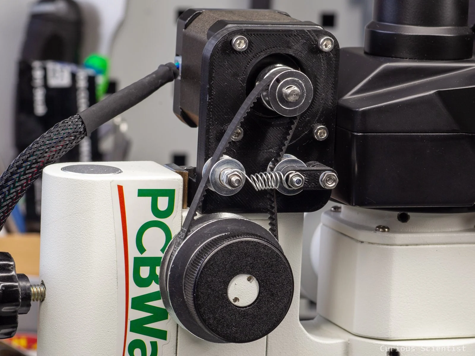
The previous Z-axis upgrade replaced the microscope’s original Z-axis. It was a rack and pinion mechanism driven by the focus adjusting knob for coarse adjustments. I used this knob, attached a timing pulley to it and drove it with a stepper motor via a timing belt. It was OK, but the speed and accuracy were not the best, and there was a noticeable backlash.
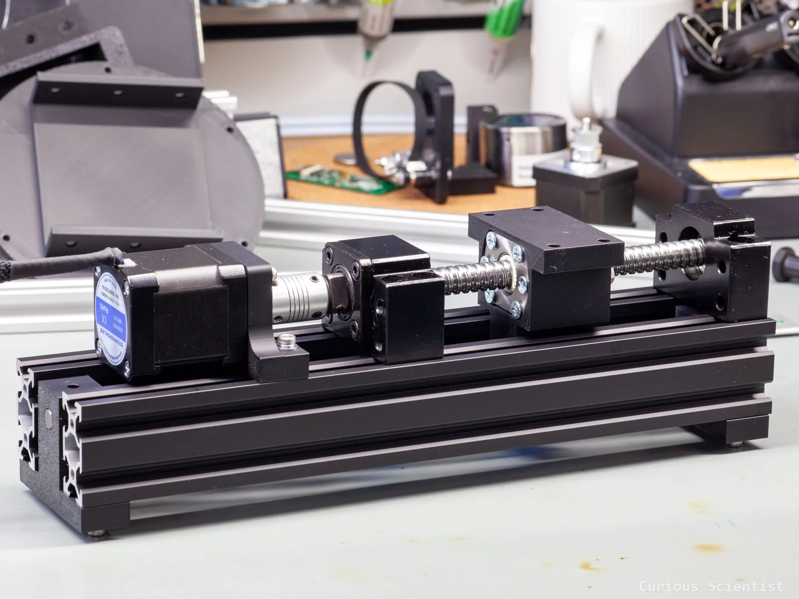
Then, I replaced this whole mechanism with a custom-built linear actuator based on an SFU1204 ballscrew. I used some support bearings, some 2040 extrusion profiles, an 8 mm shaft and some 3D-printed parts to build it. It worked better in terms of speed and accuracy than the previous mechanism, but I basically traded off stability. I noticed wobbly movement and excess vibrations. This most probably came from the not-too-stiff 3D-printed parts, especially the one that supported the whole microscope, which, without the camera and cables, weighed 2.37 kilograms.
Since I was not entirely satisfied with the DIY build, I decided that I was going to rebuild the Z-axis with better, stiffer parts.
The new build
I reimagined the whole mechanism using similar but better-built parts. The main idea, driving the microscope with a ballscrew, remained.
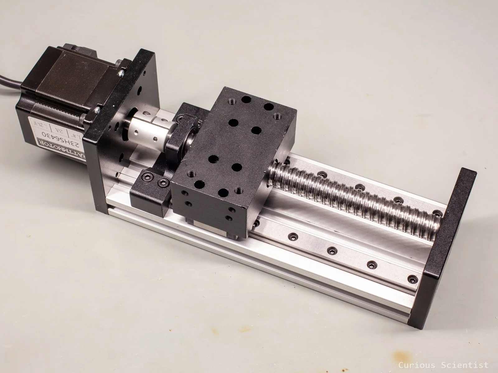
I found a nice linear actuator with a 100 mm stroke length that seemed promising:
It had a NEMA23 stepper motor, which is a bit stronger than the NEMA17 I used previously, but it is still possible to drive it with the TMC2209 driver.
It had an SFU1605 ballscrew. A step larger than the previous one. This is actually a bit bad, because its pitch is 1 mm larger, 5 mm, so I lose some resolution, but with the available microstepping, it does not really matter.
It had two MGN12-type linear guides that supported the aluminium block that accommodates the ballnut.
Everything was mounted on a 2080 extrusion profile, which made mounting easier.
The linear actuator came with some pre-installed nuts for the V-slot, but I had to replace them because I needed more of them and in a different slot from where they were. I just had to unscrew the 4 bolts at the end of the actuator and remove/replace them.
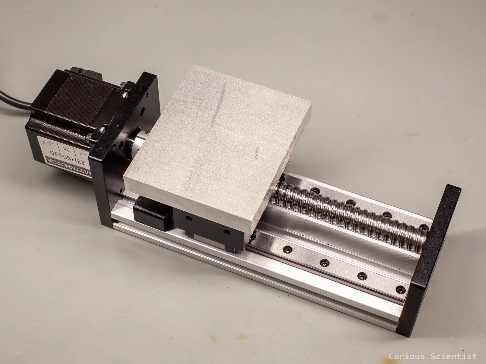
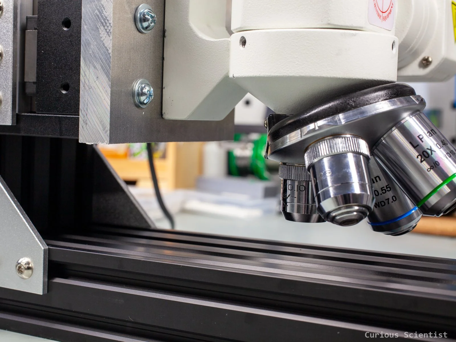
Since the previous build suffered from vibrations, I decided to make the microscope mount as sturdy as possible. I bought a 15 mm thick aluminium plate for this purpose. Having it this thick is not only because I want it to be sturdy, but I also want to provide a sufficient overhang, so I don’t have the same problem with the Y-axis as I had before. The plate will sit on top of the actuator’s ballnut block and will support the microscope.
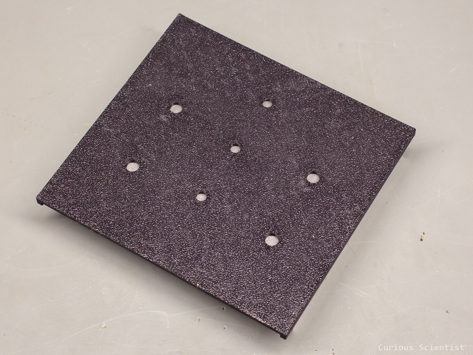
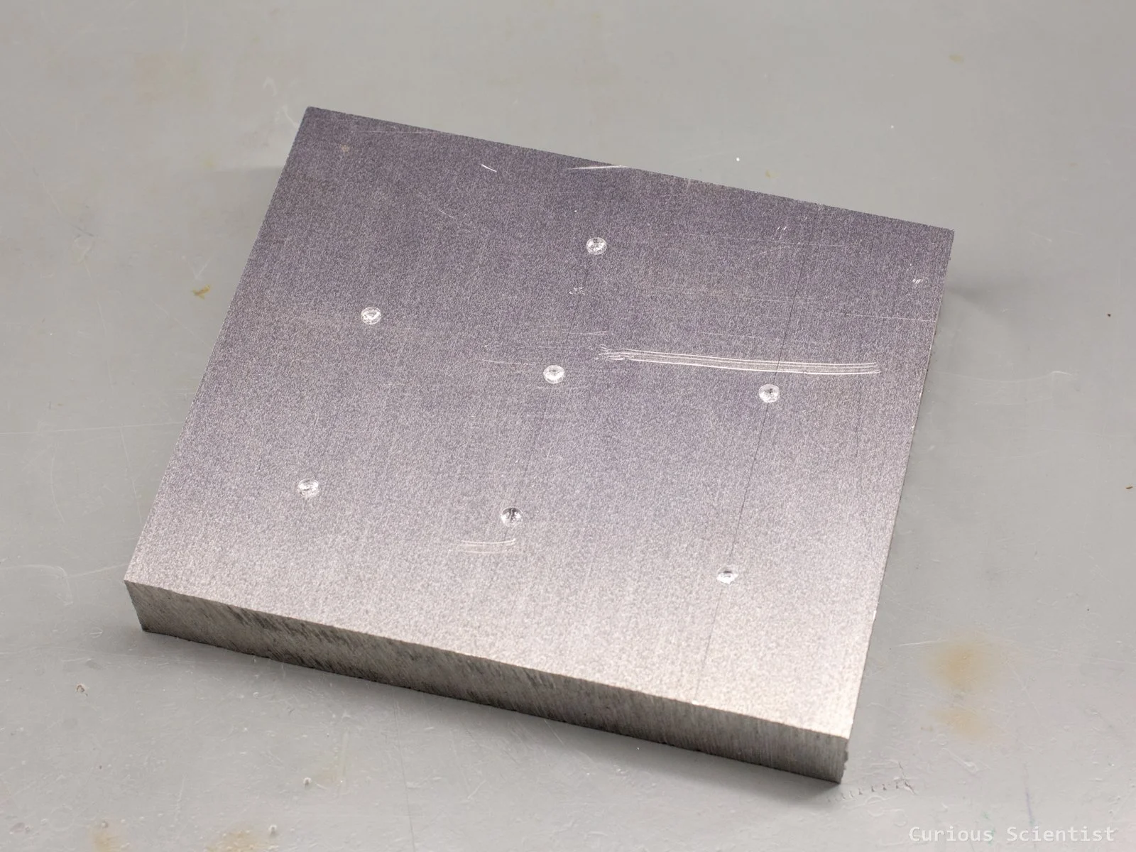
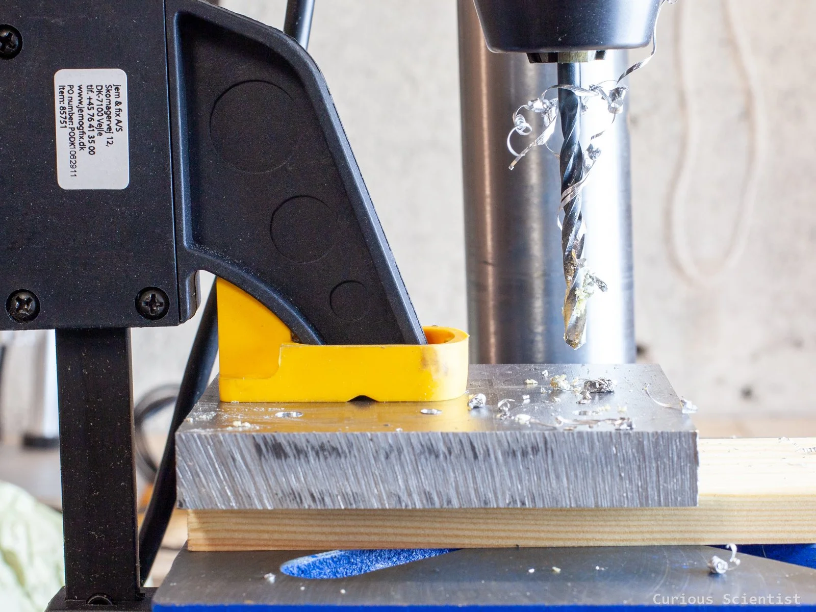
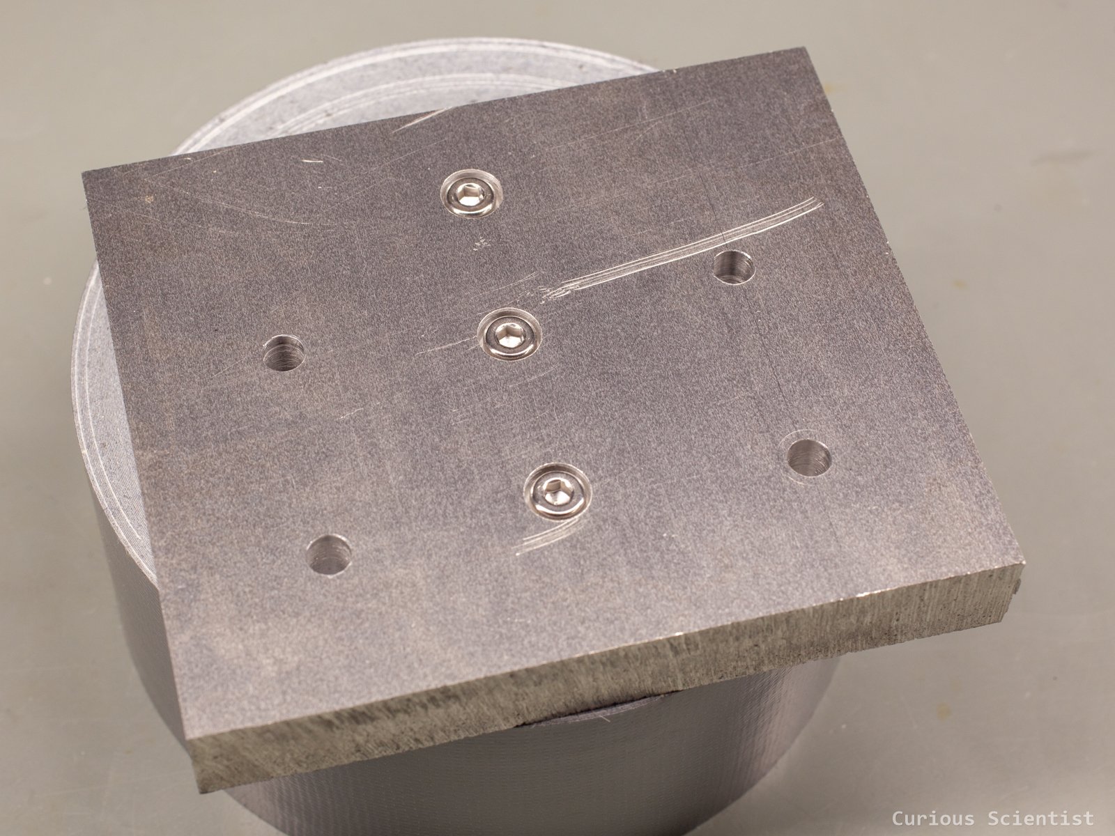
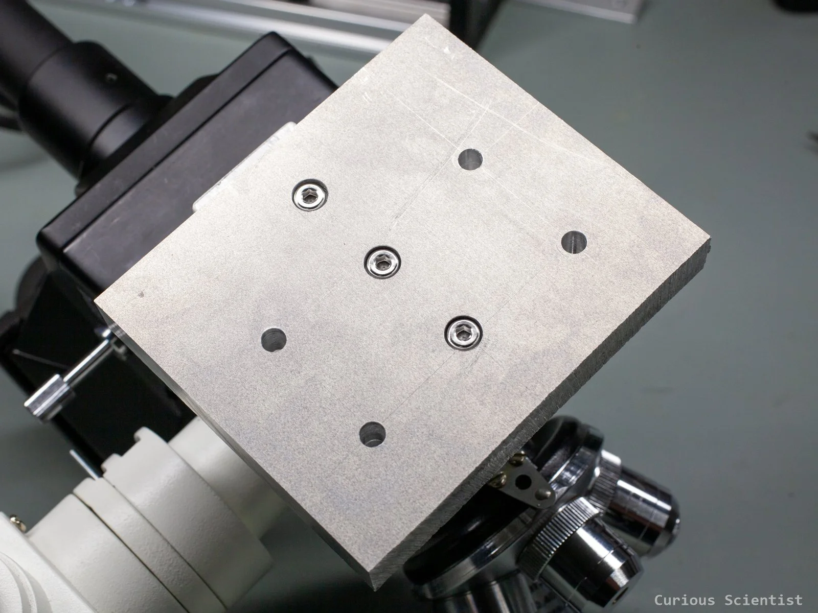
The aluminium block for the ballnut has four M5 threaded holes. Plus, I will need three M4 holes for mounting the microscope. The distances and tolerances are rather strict, and I am not the best machinist in town. But I had everything drawn in Fusion 360! So, I drew a sheet that contained the seven holes I needed to drill. I made the 3D-printed template so that it tightly snaps onto the aluminium block. Once the sheet was on the plate, I took the drill bits (4 mm and 5 mm) and marked where the holes should be drilled. To be extra sure, I did not directly drill the 4 mm and 5 mm holes. I used centre drills first, in two steps, to be sure that I had the holes aligned as well as possible. I must mention that I do not have the best drilling equipment. Apart from a wonky chuck, I do not have a proper vice to hold the specimen, so I had to improvise. After reading about drilling holes in aluminium (I read a lot before touching anything), I also placed a piece of wood under the block to avoid making an ugly hole when the drill bit goes through the plate. It worked well.
Furthermore, I had to make sure that the heads of the three M4 bolts that are supporting the microscope are sunk into the plate. So, I drilled their hole with an 8 mm bit. This was necessary because otherwise I could not mount the aluminium block on the linear actuator’s block. It had to have a flat “bottom”. The other four screws go through the plate from the “top”, so their holes were untouched.
Structural parts
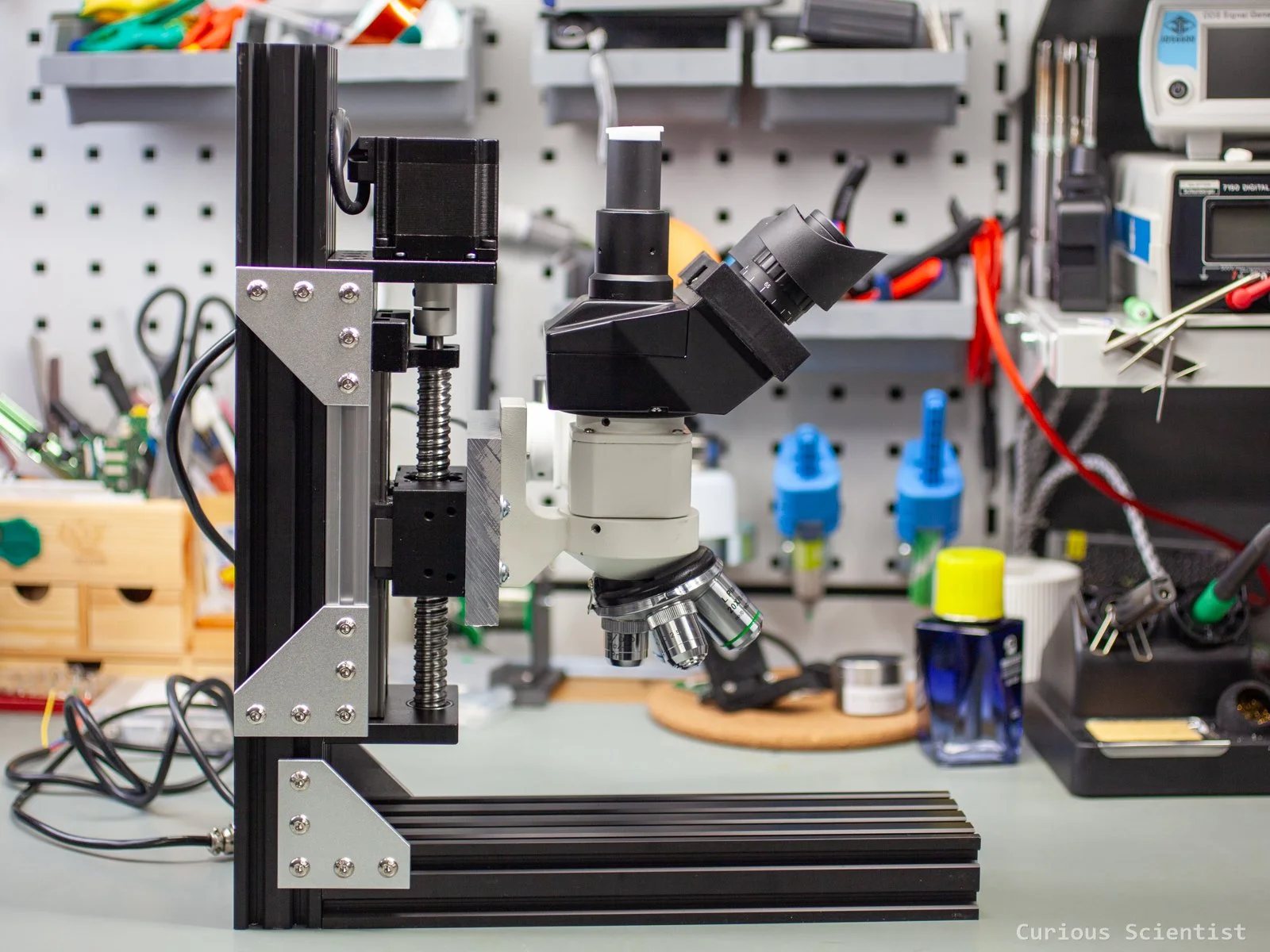
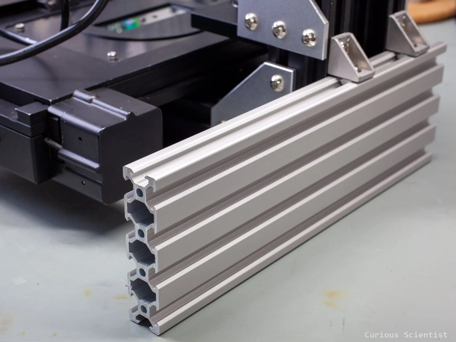
To make the whole structure stiffer and more stable, instead of using two separate 2040 profiles as previously, I used a single piece of 2080 C-beam profile. This piece is much stiffer due to its shape and due to the fact that it contains more material in a single piece.
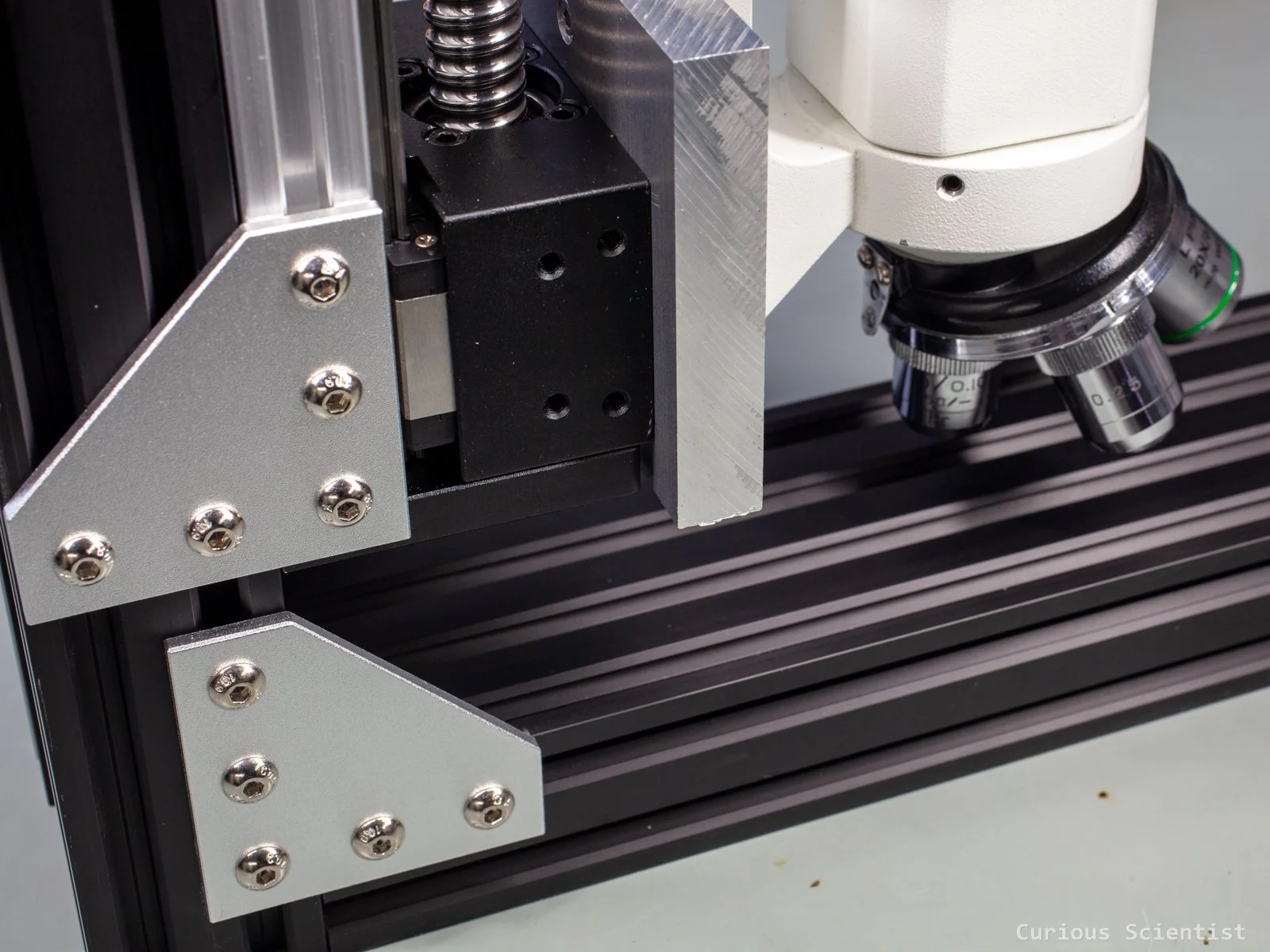
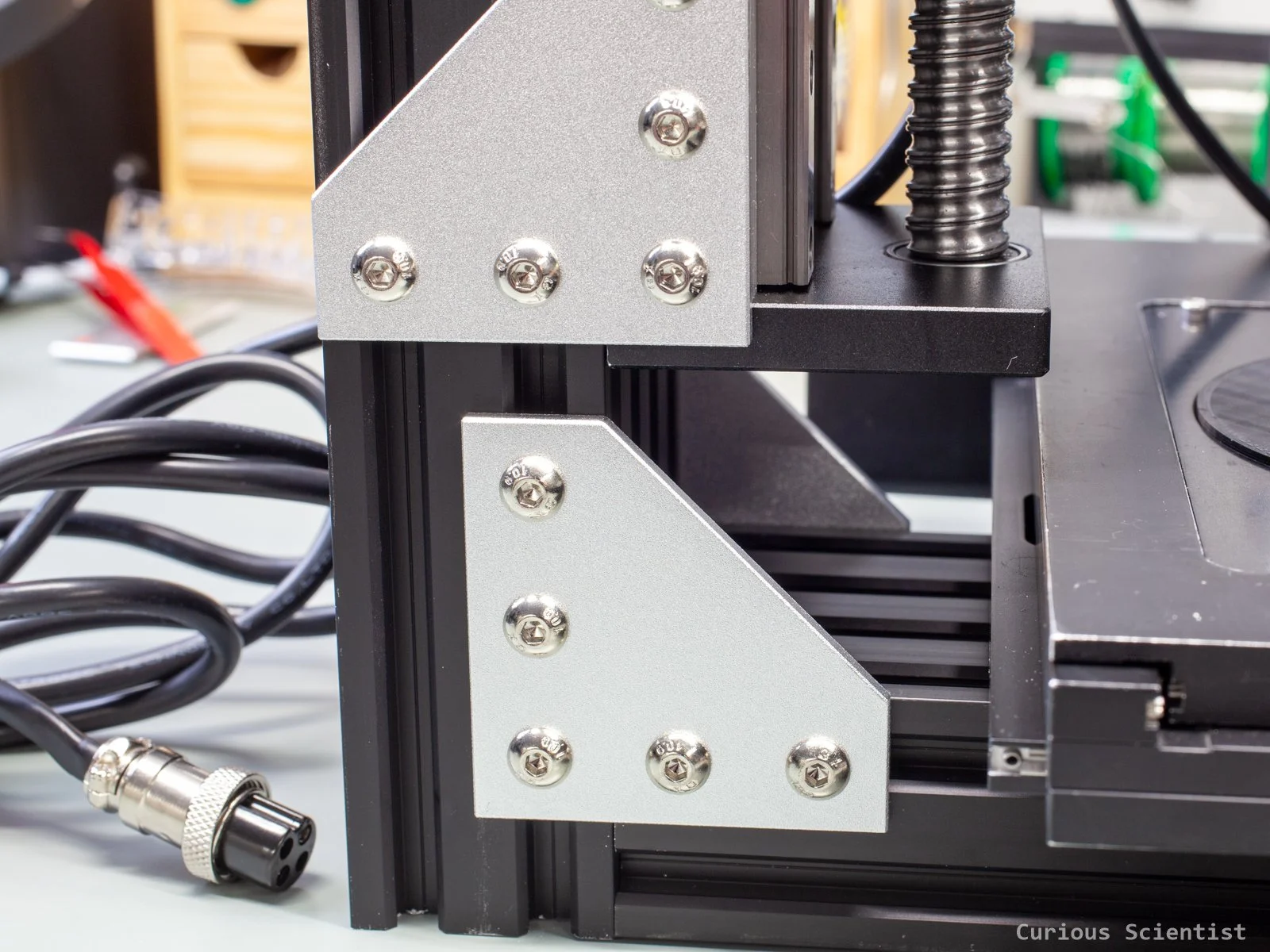
I originally bought a 750 mm piece and then got it cut into 2 pieces: a 400 mm piece and the rest. The 400 mm piece became the vertical part; the other will be the horizontal part, and the base for the X-Y stage. I bought some corner brackets for joining the pieces together. I can use this bracket both for the C-beam profiles and the linear actuator, which makes the whole assembly much simpler.
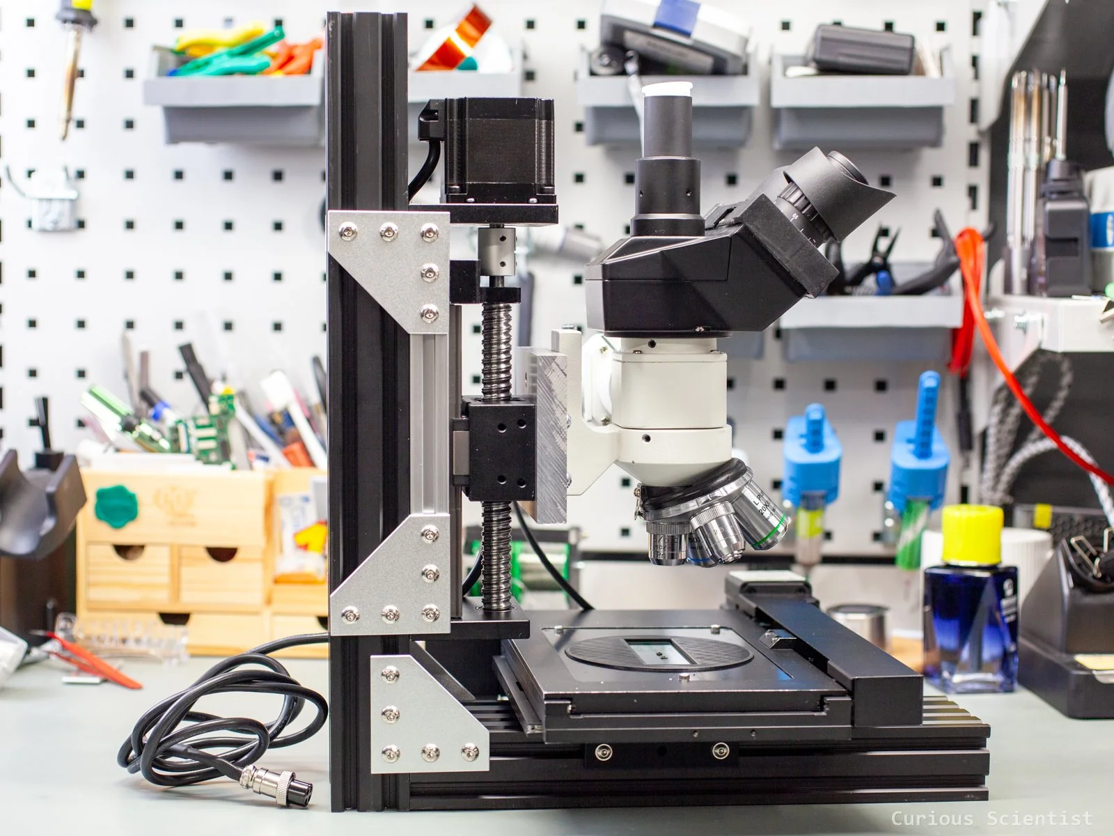
I first attached the linear actuator to the vertical piece. I used all the possible mounting positions, so in total, 20 screws hold the linear actuator and the vertical beam together. 8 in the vertical beam and 12 in the linear actuator. It should be strong enough.
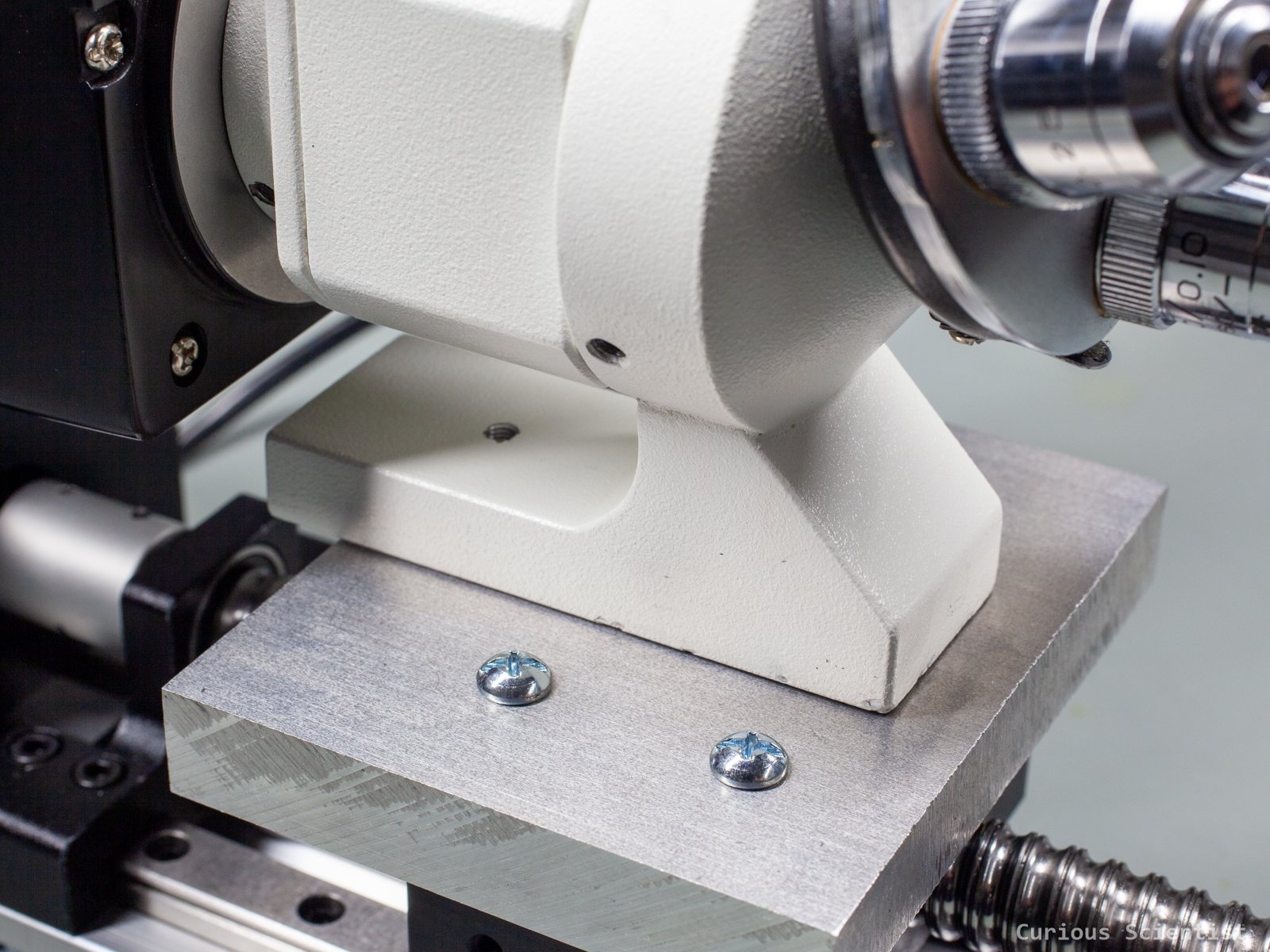
Then, I moved on to the microscope. I removed the microscope from the previous rig and attached the previously drilled aluminium block to it using three M4 bolts. Everything fit smoothly, and the heads of the bolts did not stick out. This is very important because this side of the block should sit on the actuator’s block, so it should be totally flat.
In the following step, I mounted the block with the microscope on it onto the linear actuator. I just used four long enough M5 bolts and washers. To make my work easier, I removed the light source from the microscope. This made the mounting easier because the microscope was more balanced, and it allowed me to access one of the four screws. I could not access it otherwise. After finishing the last screw, I mounted the light source back onto the microscope. It is held in place by a single set screw.
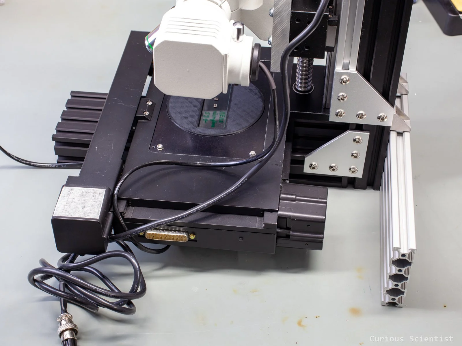
Finally, I attached the bottom profile to the microscope. I used the same corner brackets that I used for attaching the linear actuator to the vertical piece. I attached the bracket to the “top” of the bottom profile where the aluminium profile has the 2080-wide section, and not where it has the two “ears”. I did this in the hope of a stiffer joint. There is a roughly 10 mm gap left between the two brackets, in case I want to move the actuator further down. But, as it can be seen, when the actuator is at its bottom position, the shortest lens is almost touching the bottom profile. So, once the X-Y stage is mounted, I will be able to move close to the subject, and I won’t need to move all the way to the end of the actuator’s range.
Final assembly and testing
So the last step is to mount the X-Y stage. I did not change anything in the 3D-printed mount because the stage is still mounted on a 2080 profile. I still use 4 bolts; it is enough.
Once the stage is mounted, it becomes clearer how much space remains between the lenses and the stage. If I move the actuator all the way towards its end, I can move the lenses through the hole on the X-Y stage. So, the distance between the stage surface and the lenses is sufficient. If you remember, this was an issue in the previous project because I had to print another, longer microscope holder piece. After all, with the initial piece, the microscope was several centimetres above the usable working distance of the lenses. There was no way to bring the lenses to within their working distance. This is not an issue with this build.
Once the X-Y stage was in place, I could notice that the microscope became somewhat unbalanced. This is because the light source, the two stepper motors of the X-Y stage and the cable for the X-Y stage are all located on the right side of the setup. To counter this unstable condition and prevent tipping, I reused the 2080 profile from the previous build and attached it to the back of the vertical beam in a way that hinders the whole structure from tipping towards the right side. With this extra stabiliser, the setup became very sturdy.
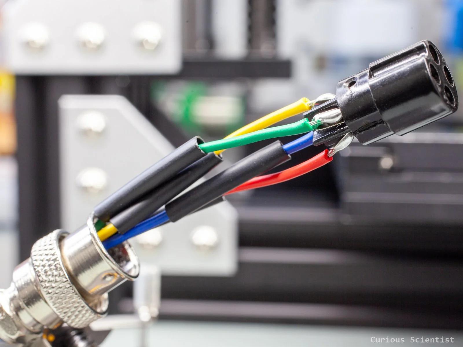
Since there is a new stepper motor in the linear actuator, I had to do some soldering. My control circuit is equipped with a 4-pin GX16 socket, so I soldered the corresponding male plug. I put heat shrink tubes on both the individual wires, plus an extra to hold everything together.
Once everything was together, I made a test homing along the Y-axis. This was a big issue in the previous build because I could not use the whole positive range of the stage along the Y-axis. With this build, I have enough overhang so that the X-Y stage can be in the centre, and I can have the full range of the Y-axis. This means that in both the positive and the negative directions, the stage can move 33 millimetres. It is a bit tight towards the vertical axis, but there are still a few millimetres to spare. Probably, I could move the bracket down to be extra safe, but I think it is fine this way. The limit switch is pressed before the stage physically touches the bracket, and the stage won’t move at extremely high speeds to create enough inertia to hit the bracket. So, it will be OK.
I also tested the homing along the Z-axis. This is still done by the TMC2209 driver’s StallGuard feature. There are no limit switches. The actuator slowly travels up until it hits the support bearing. When the motor stalls, it creates back EMF, which is detected by the driver circuit, and the motor is stopped. Then, the motor drives the microscope down by 50 mm, which is the centre of the actuator’s range, and then this point is considered the zero point of the Z-axis.
Similar to the previous setup, I attached a dial gauge to the microscope and then sent the Z-axis to different positions to see how accurately it could move. Overall, I am fairly satisfied with it. The numbers did not match the last digits, but they were close enough.
Then, I did more testing through my software as well. I was especially interested in the backlash, so I tested the Z-axis by first focusing on the subject under the microscope and then by moving it up by, let’s say, 10 mm from this position and then back to the initial position where the subject was in focus. It was almost always in focus after moving it back to the initial position. There was a tiny backlash, but when I nudged the Z-axis by 10 micrometres, I could get the subject in focus immediately. So, this means two things: the stage, and with this, all three axes have (at least, if not smaller) 10 um step resolution, and the backlash is somewhere around 10 um, which is acceptable for me. I am pretty sure that with some tuning and adjustment, I could improve this, but I am already satisfied with the results.
Furthermore, the vibrations disappeared! Not only the vibrations from the movement along the Z-axis. I also noticed that the whole microscope tolerates the vibrations much better. I used to notice vibrations, even with the original setup, when I touched the table or walked around it. Now they are absent. I think that the whole setup became stiffer overall, so the vibrations are much better dampened.
If you found this content useful, please consider joining my YouTube channel’s membership or leaving a donation.
Also, please consider using my affiliate links when buying relevant gadgets.