Mini weather station with the BME280 and the CH32V003J4M6
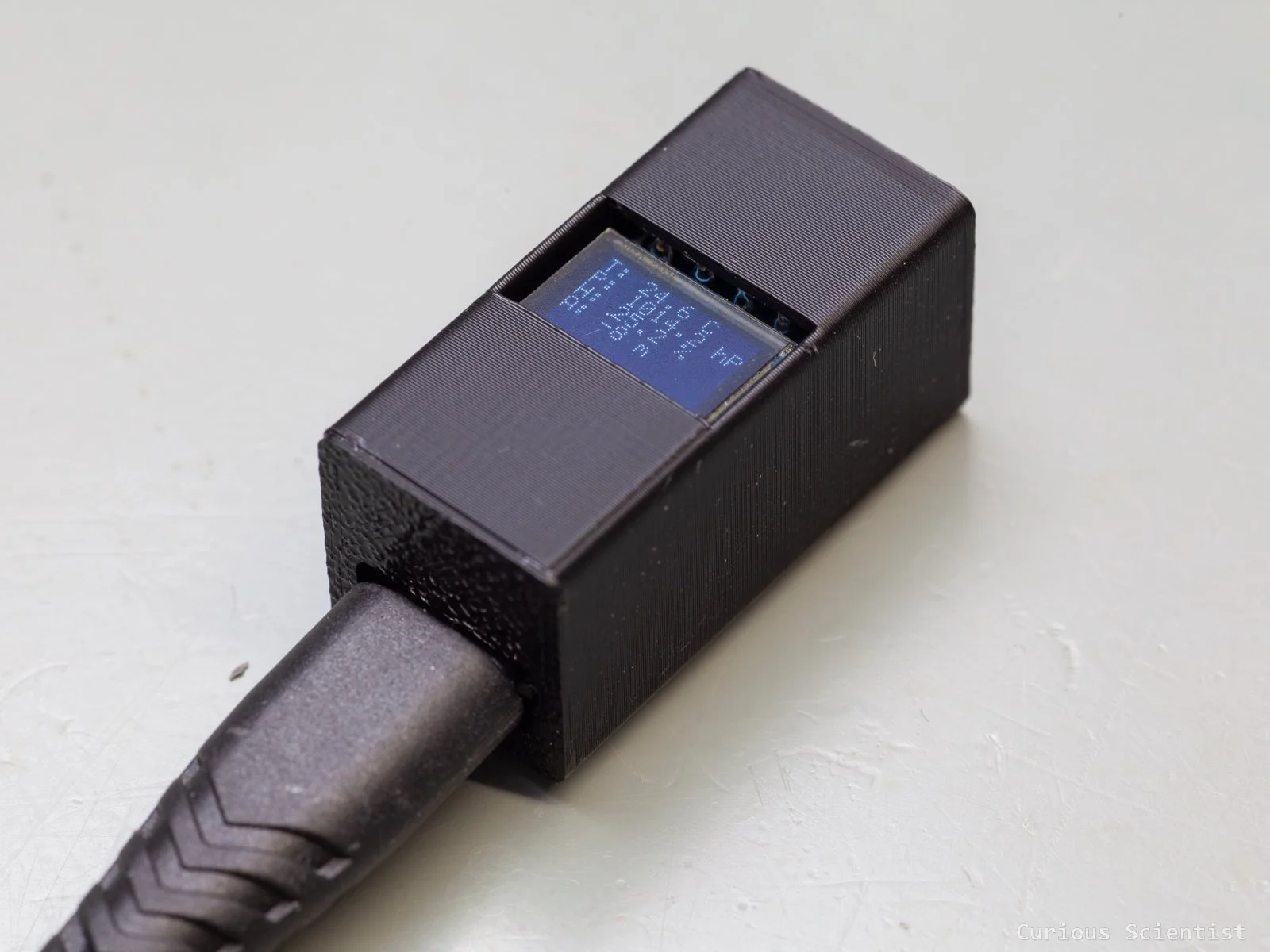
In this article, I show you another application of my CH32V003J4M6-based miniature board. Previously, I showed the board, together with some timer-based control of the WS2812B RGB LEDs. Now, I connect a BME280 combined humidity, pressure and temperature sensor and a 0.42” OLED display to the microcontroller board. It is a good exercise to show the I2C communication between multiple I2C devices and the microcontroller. The final result is a tiny weather station with a universal USB-C connection.
Introduction
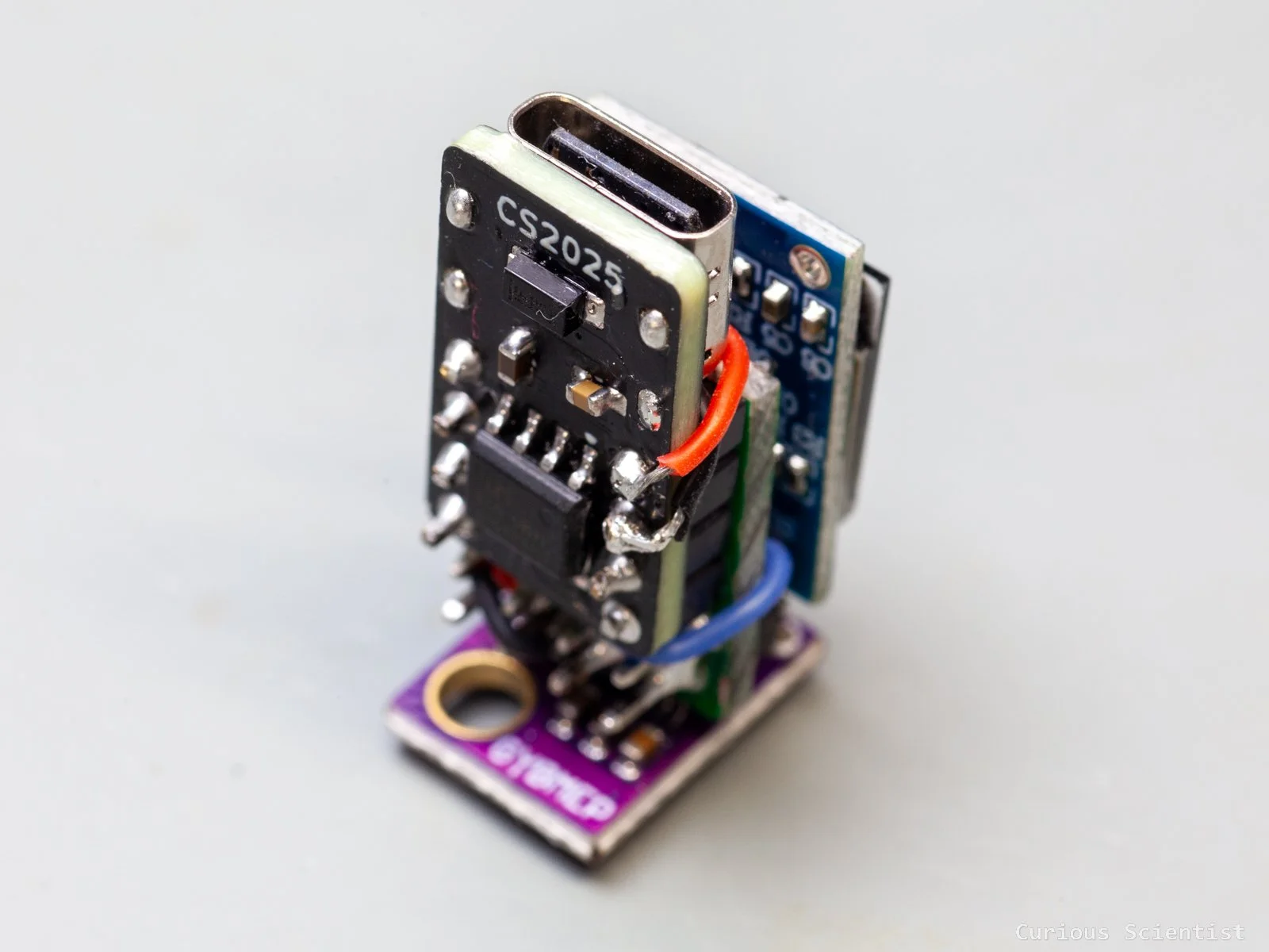
The microcontroller board does not need a very long introduction. It is based on the CH32V003J4M6 chip, and it is designed to be very small. It perfectly sits in the centre of a breadboard, and it only takes up 2 rows (of 4 pins). The USB-C connector is only used for providing power for the circuit and the peripherals connected to it. To program the microcontroller, one must use a WCH-LinkE programmer. The board was designed to be used as a standalone microcontroller board. I designed it with a power-only USB-C connector. For the sake of miniaturisation, I did not add a USART-to-USB chip, which would have made it easy to connect the chip to a computer via a USB port. However, it is possible to bit-bang a USB protocol for the chip, but I don’t have those skills.
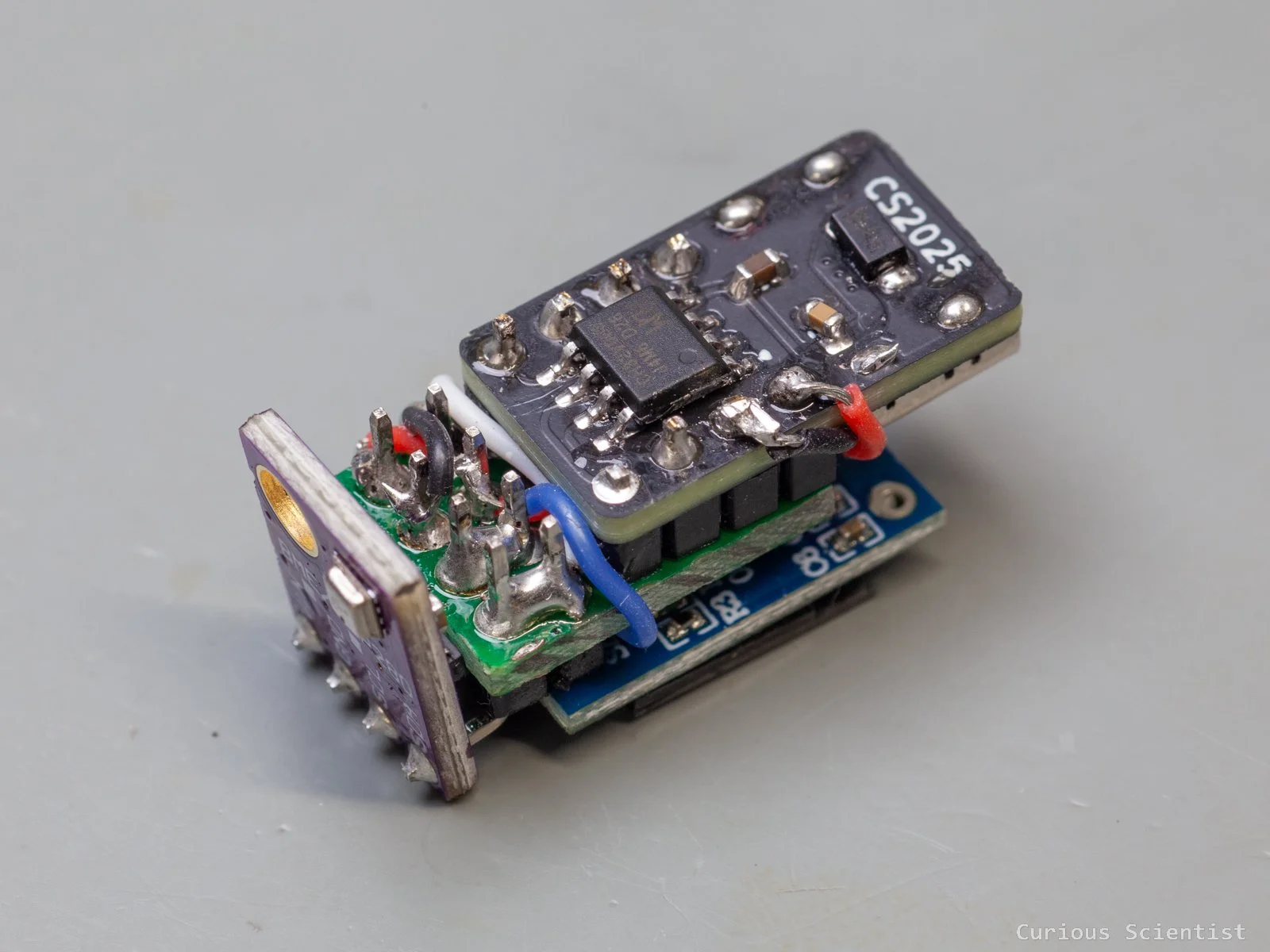
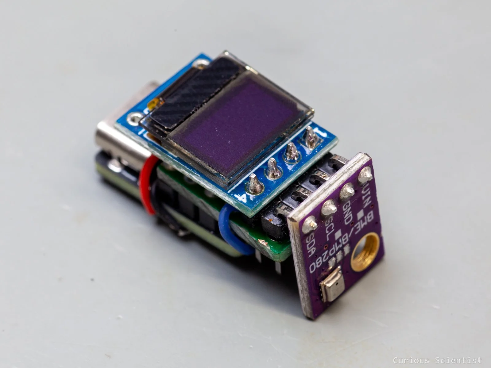
The peripherals: the BME280 and the 0.42” OLED display are powered by 5 volts, and they are connected to the same I2C bus. Since the device is a 5V-only device, it is very important to pick a BME280 module that can operate at 5 volts. The display is, however, not that picky about the voltage; it can be driven by 5 V, and it can be used with 5 V signals without issues. My only “issue” is that the pin layout of the display and the sensor is slightly different: the SDA and SCL pins sit at the same place, but the GND and VCC pins are the opposite. So, when I put the circuit together, I had to do a little extra work to connect the power rails between the display and the BME280 sensor.
Of course, before soldering everything together into a relatively small setup, I assembled everything on a breadboard. This allowed me to develop and polish the firmware properly.
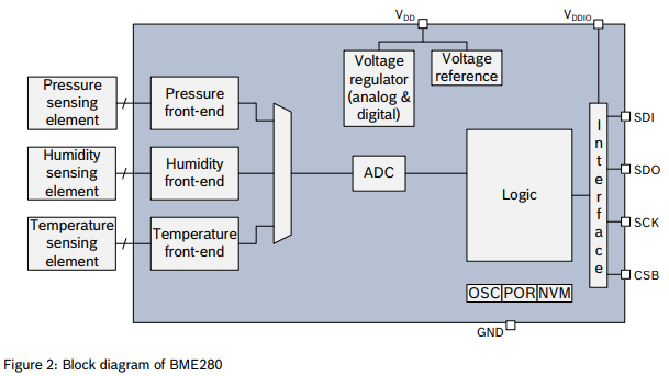
BME280 Sensor
This sensor is a MEMS-based temperature, humidity and pressure sensor. Using the pressure data, we can even determine the altitude. It can be used both as an SPI or as an I2C device. In this demonstration, I go with I2C. The operating voltage of the sensor itself is up to 3.6 V, but I use the sensor embedded in a board that allows it to be used with a 5 V supply voltage and 5 V signals. Furthermore, I picked a board that is exactly the same width (4 pin wide) as the microcontroller board and as the 0.42” OLED board. So, the whole setup I tacked together has a uniform width.
Communicating with the BME280 sensor
I will only focus on the communication with the BME280 sensor, because the communication with the OLED display has already been explained in an earlier article. I just reused my library I developed earlier.
To understand the communication, we have to read the datasheet of the sensor. The core of the output is the ADC output values. We need to read the ADC values for the temperature, pressure and humidity, and then we must use a set of calibration parameters to calculate the actual temperature, pressure and humidity values. The calibration parameters are also called trimming parameters, and they are programmed into the devices’ non-volatile memory during production. So, apart from reading the ADC values, we also need to retrieve these trimming parameters from the BME280 chip.
Once the set of ADC readings and trimming parameters are obtained, each parameter (T, P and H) has its own compensation formula that allows us to convert the readings into readable parameters. These formulas can be found in the datasheet of the chip. Actually, they not only provide the formulas, but also the code for each formula as well. There’s only a tiny tweaking needed to make it work with the microcontroller.
The trimming parameters, the so-called t_fine fine resolution temperature value and the address of the device can be stored together in a struct. All the trimming parameters are declared and defined according to Table 16 in the datasheet.
typedef struct
{
    uint8_t addr;
    int32_t t_fine;
    uint16_t dig_T1; int16_t dig_T2, dig_T3;
    uint16_t dig_P1; int16_t dig_P2, dig_P3, dig_P4, dig_P5, dig_P6, dig_P7, dig_P8, dig_P9;
    uint8_t  dig_H1, dig_H3;
    int16_t  dig_H2, dig_H4, dig_H5;
    int8_t   dig_H6;
} bme280_t;
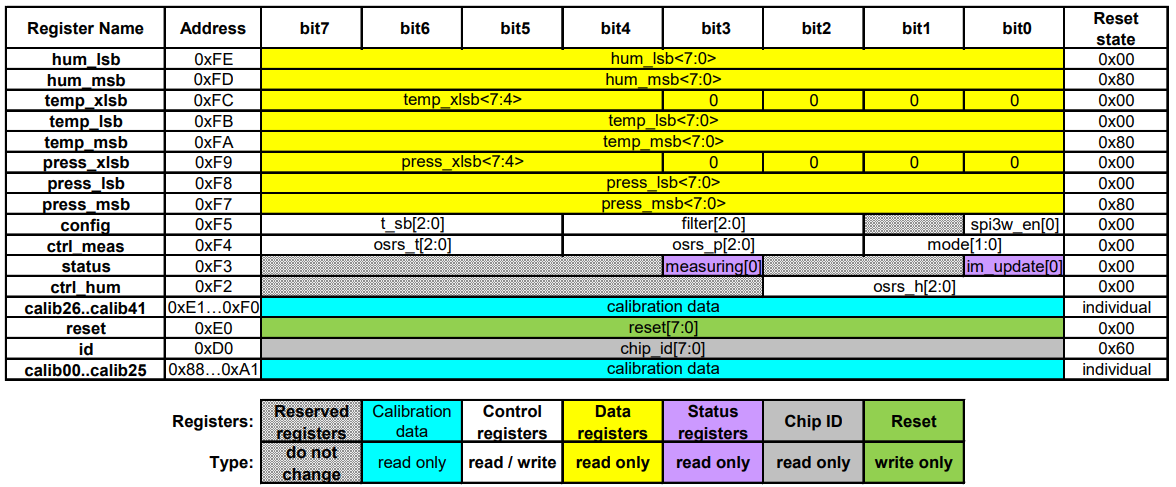
Then, the registers mentioned in Chapter 5.4 in the datasheet are also incorporated into the code as definitions. It allows us to read the code a bit easieras it was a document rather than a bunch of hex literals.
#define REG_ID        0xD0
#define REG_RESET     0xE0
#define REG_CTRL_HUM  0xF2
#define REG_STATUS    0xF3
#define REG_CTRL_MEAS 0xF4
#define REG_CONFIG    0xF5
#define REG_DATA      0xF7
#define CHIP_ID       0x60
#define RESET_CMD     0xB6
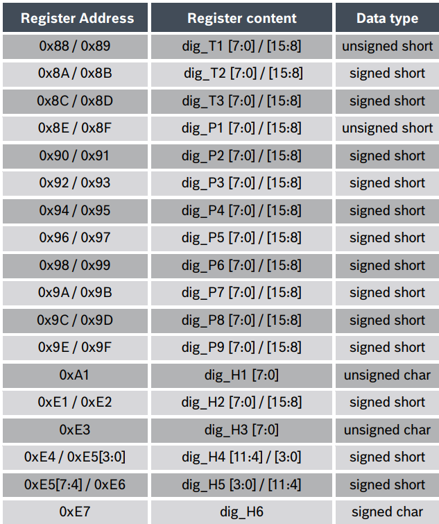
Compensation parameter storage, naming and data type
Functions
The library contains a few functions that help us to communicate with the sensor.
There are three helper functions, wr8, rd8, and rdn that allow us to write a byte, read a byte or read n bytes from the BME280 sensor.
There are two additional helper functions to convert byte order. The u16le converts two bytes (16 bits) in little-endian (“le”) order into an unsigned 16-bit integer (u16). And the s16le function does the same conversion, but it returns a signed 16-bit value. The calibration parameters are a mixture of signed and unsigned values. These helpers help to avoid issues caused by endianness or incorrect sign interpretation.
Then, we arrive at a more exciting function, which reads the trimming parameters from the sensor into the struct fields. Most of the reading and passing values are straightforward, but there are two exceptions that need a little attention:
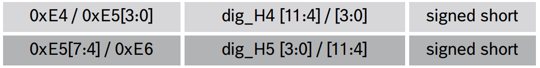
H4 and H5 are stored in a bit weird way because part of H4, as well as part of H5 are stored in register 0xE5. H4 is under 0xE5 [3:0] (“low-nibble”), and H5 is under 0xE5 [7:4] (“high-nibble”). Therefore, a little bit-shifting is applied when the values for these two parameters, H4 and H5, are retrieved.
We also have an initialisation function that brings the sensor to a known state, verifies its identity and loads the calibration data. First, the code stores the address (it can choose from two, 0x76 or 0x77, depending on the hardware setup). Then it reads the chip ID and compares it with the expected 0x60 value. Then, after a soft reset, the trimming parameters are read out, and a default measurement configuration is applied. After the function has successfully run, the library has everything it needs to compute the compensated T, P and H values.
The above-mentioned measurement configuration consists of 6 parameters. It has its own function implemented. First, the oversampling parameter for the humidity is written. It is important to start with this write operation according to Chapter 5.4.3 in the datasheet: “Changes to this register only become effective after a write operation to “ctrl_meas”. What this means is that writing the ctrl_hum alone does not immediately apply humidity oversampling. The oversampling gets latched when we later write ctrl_meas. If we were to do ctrl_meas first, the ctrl_hum afterwards would not be applied, and it would only take effect when another ctrl_meas write happens.
uint8_t bme280_configure(bme280_t *bme,
                      uint8_t osrs_t, uint8_t osrs_p, uint8_t osrs_h,
                      uint8_t mode,
                      uint8_t filter,
                      uint8_t standby)
{
    osrs_t &= 7; osrs_p &= 7; osrs_h &= 7;
    mode &= 3; filter &= 7; standby &= 7;

    if (!wr8(bme, REG_CTRL_HUM, osrs_h)) return FAIL;

    uint8_t cfg = (uint8_t)((standby << 5) | (filter << 2));
    if (!wr8(bme, REG_CONFIG, cfg)) return FAIL;

    uint8_t meas = (uint8_t)((osrs_t << 5) | (osrs_p << 2) | mode);
    if (!wr8(bme, REG_CTRL_MEAS, meas)) return FAIL;

    return OK;
}
So, using this knowledge, we can sneak in a command in between to apply the settings for the standby and filter registers.
As you notice in the code, there are some bit shifting (masking) here and there because certain parameters share the same register. For example, the ctrl_meas (0xF4) register contains both the osrs_t and osrs_p values, plus it also contains the mode value. A better understanding can be achieved by studying Table 18 in the datasheet.
The configure function might look a bit intimidating, but it is quite simple and logical when it is broken up into smaller bits. To reiterate: three configuration registers, ctrl_hum (0xF2), config (0xF5) and ctrl_meas (0xF4) are involved here. They control the humidity oversampling, the standby time and IIR filter, the temperature and pressure oversampling and the mode bits.
In the beginning of the function, each parameters that is used are constrained to legal bit widths. This is needed because the registers use small bitfields. The oversampling registers (osrs_x), the filter and the standby registers are 3-bit fields, so their valid range is 0 - 7. The mode is a 2-bit field, so its valid range is 0 - 2. Masking avoids accidental corruption if invalid values are passed.
Finally, we just need to type in the compensation formulas from Chapter 4.2.3 in the datasheet and adjust them according to the coding environment.
static uint8_t wr8(bme280_t *b, uint8_t reg, uint8_t v)
{
    return I2C_WriteRegisters(b->addr, reg, &v, 1);
}

static uint8_t rd8(bme280_t *b, uint8_t reg, uint8_t *v)
{
    return I2C_ReadRegisters(b->addr, reg, v, 1);
}

static uint8_t rdn(bme280_t *b, uint8_t reg, uint8_t *buf, uint8_t n)
{
    return I2C_ReadRegisters(b->addr, reg, buf, n);
}

static uint16_t u16le(const uint8_t *p)
{
     return (uint16_t)p[0] | ((uint16_t)p[1] << 8);
}

static int16_t s16le(const uint8_t *p)
{
     return (int16_t)u16le(p);
}
uint8_t bme280_init(bme280_t *bme, uint8_t addr)
{
    if (!bme) return FAIL;
    bme->addr = addr;
    bme->t_fine = 0;

    uint8_t id = 0;
    if (!rd8(bme, REG_ID, &id)) return FAIL;
    if (id != CHIP_ID) return FAIL;

    if (!wr8(bme, REG_RESET, RESET_CMD)) return FAIL;
    Delay_Ms(5);

    for (uint8_t i = 0; i < 50; i++)
    {
        uint8_t st;
        if (!rd8(bme, REG_STATUS, &st)) return FAIL;
        if ((st & 0x01) == 0) break;
        Delay_Ms(2);
    }

    if (!read_cal(bme)) return FAIL;
    return bme280_configure(bme, 1, 1, 1, 3, 0, 5);
}
BME280 memory map
Additional resources
Buy the relevant parts using my affiliate links
Get the miniature PCB!