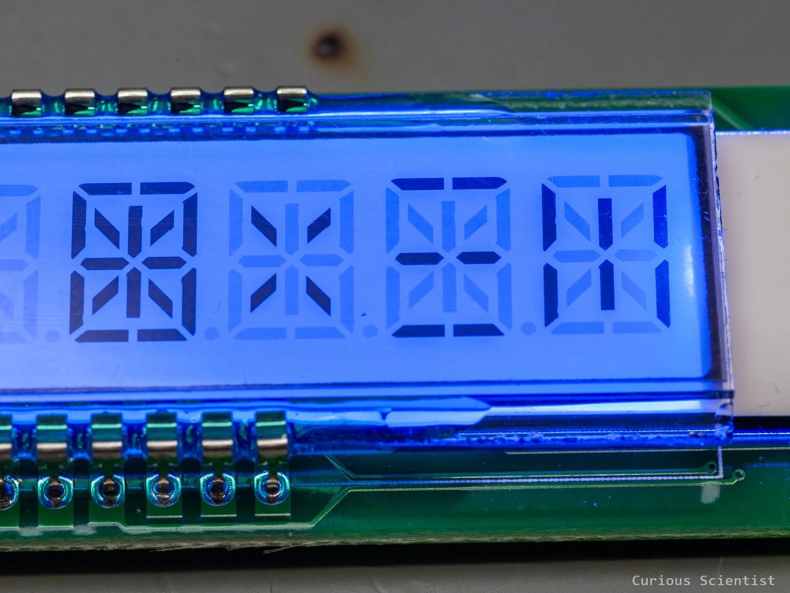
CH32V003F4P6 with DM8BA10 alphanumeric display
In this article, I show you how to drive a DM8BA10 display using a CH32 microcontroller. This video belongs to my CH32 tutorial series, so I explain everything in detail, and I show you how I built up the library from first principles. Earlier, I introduced a firmware for OLED displays, but this time, I show a different display that operates with segments, instead of pixels. This specific display has 10 digits, and each digit consists of 16 segments. Furthermore, there are 9 separator dots that can be used both as a decimal or a thousand separator, depending on the style of how we display numbers on the display. This large flexibility allows us to use the display both for numbers and characters. So both text and numerical values can be shown on the display. I will display numbers and text locally generated on the microcontroller as well as received via the serial terminal.
Introduction
So, as I mentioned in the beginning, the display has 10 digits, and each digit consists of 16 segments. There are three vertical and three horizontal zones, and each zone contains two segments. So, this is 12 segments already. The other four come from the two diagonal zones, where each zone contains 2-2 segments.
The segments are driven by a TM1622 chip. This is a dedicated LCD driver chip. It has 32 × 8-bit RAM, which is used to store the data for the segments we want to display. The data is sent to the chip via a simple serial interface.
The serial interface is managed by 3 pins: CS, WR and DATA. The CS pin is used to initialise the serial interface and to terminate instruction and/or data transmission. It must be pulled LOW to allow communication with the TM1622 chip. The WR pin is the write clock input pin. On each rising edge of WR, the data on the data pin (basically, the state of the DATA pin) is written into the RAM of the chip. Finally, the DATA pin is the serial input/output pin. Setting this pin to LOW or HIGH sets the data bit that is used in the chip.
In fact, the chip itself has more communication pins, but they are not exposed on this specific display’s board.
In this example, I use a CH32V003F4P6 chip to drive the display.
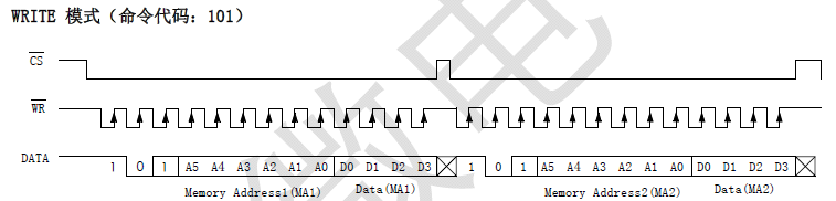
Timing chart of the write operation
Different type of segments of the display
Implementation
The display does not require super-fast communication, or a certain strict protocol, like I2C or SPI, so we just have to toggle the WR, CS and DATA pins to manipulate the segments on the display. The timings can be fairly relaxed as long as the pulses are sent to the device in an orderly manner.
First, we have to create a function that transfers bits to the LCD driver chip from the microcontroller. Based on the above-mentioned timing chart, the control sequence can be bit-banged. First, all three pins are set to HIGH. This can be done already when we initialise the circuit.
Then, CS is pulled LOW to initiate the transaction, and the rest of the transfer can be wrapped in a for() loop that iterates as many times as many bits are in the data to be transferred.
Next, we pull the WR pin LOW before putting the next bit on the data line. This follows the datasheet’s requrement which says that the chip latches the content of the DATA on the rising edge of WR. So, then based on whether we have an LSB-first or MSB-first data chunk, we shift the data in or out (right or left) by 1 bit and toggle the DATA pin accordingly.
In LSB mode, if the lowest bit is 1, the DATA pin is pulled HIGH, otherwise it is driven LOW. In MSB mode, it is a bit trickier: we mask the highest bit by considering the number of total bits, and then we check if this bit is 1 or 0. Then we set the DATA pin accordingly.
It is important to discuss why we need LSB-first (right-to-left) and MSB-first (left-to-right) modes: It is due to how the TM1622 chip expects data. Address bits are A5-A0, but data bits are in D0-D3 order. So, the addresses must be sent as MSB-first data, and the data must be sent as LSB-first. On the microcontroller, both data and addresses are stored in the same format, but they must be shifted to the display in a different order.
Finally, after some delay, the WR pin is pulled back to HIGH, and after another short delay, the code jumps back to the top of the iteration again and starts to transfer the next bit by toggling the WR and DATA pins accordingly.
You might notice that I used delays, so it is a blocking code. But it blocks for just a few microseconds, plus this demonstration focuses more on understanding the communication protocol of the display and not on implementing a non-blocking display driver. The code is freely available on my GitHub, so if you want, you can download it and convert it into a non-blocking one.
static void TM1622_SendBits(uint16_t value, uint8_t bitCount, uint8_t order)
{
    for(uint8_t i = 0; i < bitCount; i++)
    {
        WR_L();
        if(order == LSB_FIRST)
        {
            if(value & 0x0001U){DAT_H();}
            else{DAT_L();}
            value >>= 1;
        }
        else
        {
            if(value & (1U << (bitCount - 1))){DAT_H();}
            else{DAT_L();}
            value <<= 1;
        }
        Delay_Us(TM1622_CLK_US);
        WR_H();
        Delay_Us(TM1622_HOLD_US);
    }
}
Creating and printing characters
After we are able to send data to the display, we need to figure out how to display intelligible characters on it. With each data transfer, we can send a 4-bit data package, also called a ‘nibble’. This data transfer is the same as before; we just reuse the previously created SendBits() function and organise the lines into a new function that helps us to send data to the display.
First, we have to understand the concept of addressing the segments of the display. Each digit consists of 16 segments. This means that within a digit, there are 4 nibbles (4×4 = 16). Each nibble has its address range. The first nibble starts at 0x00 address, the second starts at the 0x04 address, the third starts at the 0x08 address, and so on, all the way up to 0x24. Within each of these 4-bit packages, we just set the values to 1 wherever we want the segment to be ON, and to 0 wherever we don’t. This immediately suggests that if we write all segments with zeroes, we can erase the display.
To draw a full character, we need another function that orchestrates the data transfer for four nibbles. This is just a function that takes the position of the digit and a 16-bit value that represents a character. So, this function is just a piece of code that bundles four WriteNibble() functions together.
First, based on the selected digit, we fetch the base address. This is one of every 5th nibble addresses, since every 5th nibble belongs to a new character. Then, it is really just four subsequent WriteNibble() functions where the base address is incremented for each new nibble, and the data is shifted and masked according to the data that must be placed in the nibble that is being addressed.
The more interesting part is the creation of the characters.
As I said, the working principle is fairly easy. We light up certain segments among those 16 segments to visualise a certain letter or number. I did this manually, and to speed up the process, I made an Excel sheet for it. The concept of the Excel sheet is the following: I drew a block of cells that more or less resembles the 16 segments within a character. Then, I added a conditional formatting to each segment so they turn green when I put an ‘x’ character in the cell, and they turn white when the cell is empty. This helps me to draw the characters very quickly and to get visual feedback on the expected appearance of the character.
To know which segment is which number, I had to create a function that walks through the 16 segments and lights them up, one at a time. I simply drew a dummy display segment in my notebook and noted down each segment’s serial number. Then I assigned it to my Excel table.
Then, I made a table that consists of 2 rows: the top row is just columns from 0-15, and the bottom row is filled in based on which segment is active (contains an ‘x’). This creates a bridge between the visual and the numerical representation of the segments.
Finally, based on the active segments, the Excel sheet generates a decimal and a hexadecimal sum of the active segments. This number represents the drawn character, and this is the number that we split up into 4 nibbles by shifting and masking it, and send to the display.
Finally, there is one last thing: we need to display the decimal points. This was a bit tricky to figure out because I had no idea about how they are accessed. Then, I did some “bit-walking” beyond the 0x28 address, and I found that at 0x29, 0x2B and 0x2D addresses we can manipulate the decimal dots. Under one address, we can activate one dot at a time. But we can have multiple dots on the display at the same time, since we can use them as thousand separators, or something similar.
void TM1622_SetDecimalInGroup(uint8_t group, uint8_t index)
{
    uint8_t addr;
    uint8_t data;

    switch(group)
    {
        case 0: addr = 0x29; break;
        case 1: addr = 0x2B; break;
        case 2: addr = 0x2D; break;
        default: return;
    }

    if(index > 2) return;

    data = (1U << (index + 1));
    TM1622_WriteNibble(addr, data);
}
void TM1622_WriteNibble(uint8_t addr, uint8_t data)
{
    if(addr >= TM1622_RAM_NIBBLES) return;

    Delay_Us(TM1622_SETUP_US);
    CS_L();
    Delay_Us(TM1622_SETUP_US);

    TM1622_SendBits(0b101, 3, MSB_FIRST);
    TM1622_SendBits(addr, 6, MSB_FIRST);
    TM1622_SendBits(data & 0x0F, 4, LSB_FIRST);

    Delay_Us(TM1622_SETUP_US);
    CS_H();
    Delay_Us(TM1622_SETUP_US);
}
void TM1622_WriteDigitRaw(uint8_t digit, uint16_t segData)
{
    if(digit >= 10) return;
    uint8_t base = digitAddr[digit];

    TM1622_WriteNibble(base + 0, (segData >> 12) & 0x0F);
    TM1622_WriteNibble(base + 1, (segData >> 8)  & 0x0F);
    TM1622_WriteNibble(base + 2, (segData >> 4)  & 0x0F);
    TM1622_WriteNibble(base + 3, (segData >> 0)  & 0x0F);
}
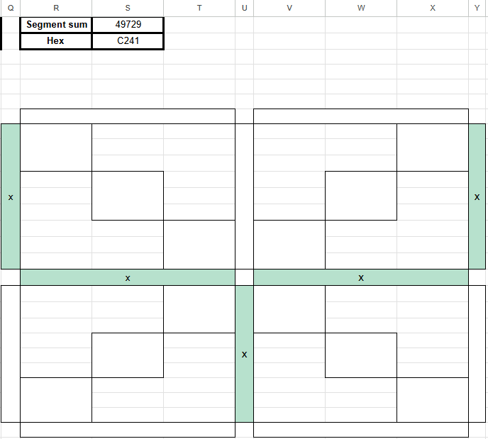
Excel drawing tool showing the letter “Y” and its decimal and hexadecimal code.
Printing text
Similar to my bit-banged OLED library, I made a font array that contains the numbers from 0 to 9, all the capital letters, and some symbols as well. This font array matches the regular ASCII character set, so it is very easy to call characters from it with a few lines of code. However, certain characters are hard or impossible to display on this display, so I skipped them and replaced them with empty space. For example, the AND symbol (‘&’) is not super easy to draw with the available segments, and it is not a very often used character, so I replaced its HEX code with 0x0000, which is the space. And I followed the same logic for the rest of the difficult characters in order to maintain the structure and order of the ASCII character set table.
When we print an actual character using this table, we pass a char to a function that returns the corresponding position of the font in the font[] array. The first character that is used from the ASCII table is the space, whose code is 0x20. But, in our font[] array, it is located in the first place (0th index). So, to convert the char to a font index, we just have to subtract 0x20 from it. As I said, the font[] array maintains the order of the original ASCII table, so for any further characters, this strategy works fine.
Then, the fetched 16-bit value is just passed to the WriteDigitRaw() function that breaks the number down into four nibbles and sends it to the display.
Printing a string is done along the exact same lines, but instead of printing just one character, we print multiple characters. So, there is a helper function that iterates through an array that stores the characters of a text we want to display and in each iteration, it passes the next character to the display.
static uint16_t TM1622_GetFontForChar(char c)
{
    if((uint8_t)c < 0x20 || (uint8_t)c > 0x5D)
    {
        return 0x0000;
    }

    uint8_t index = (uint8_t)c - 0x20;
    return fonts[index];
}
void TM1622_PrintChar(uint8_t pos, char c)
{
    uint16_t pattern = TM1622_GetFontForChar(c);
    TM1622_WriteDigitRaw(pos, pattern);
}
Printing floating-point and negative numbers
We can now print text, but this option, on purpose, is not able to print floating-point numbers. This is because the character set does not contain any decimal points, but the display has built-in decimal dots. So, I decided to separate the floating-point number printing into a dedicated function. This function receives the floating-point number as a string of characters and then decides which decimal point should be turned on and prints the number.
To be able to handle negative numbers, the first character location (leftmost block) is reserved for the minus symbol. Either it shows nothing (positive numbers), or it shows a minus symbol. So, the first numerical character is printed in the second block from the left side of the display. Based on the received string that represents the floating-point number, the code decides whether it needs to print a minus symbol or not. Then, the function investigates if the string contains a decimal point in the actual iteration. If it does, it determines the address of the decimal point and prints it on the display. Finally, it checks what the actual numerical character is and prints it in the corresponding position.
In the meantime, the function carefully keeps track of each position, so the numbers, the decimal point and the optional minus symbol all end up at their designated place on the display.
void TM1622_PrintNumberString(const char *str)
{
    uint8_t logicalPos = 0;
    int8_t lastPrintedPos = -1;

    while(*str != '\0' && logicalPos < 9)
    {
        if(*str == '-')
        {
            TM1622_WriteDigitRaw(9, fonts['-' - 0x20]);
        }
        else if(*str == '.')
        {
            if(lastPrintedPos >= 0)
            {
                TM1622_SetDecimalAtPosition((uint8_t)lastPrintedPos+1);
            }
        }
        else if(*str >= '0' && *str <= '9')
        {
            TM1622_PrintCharAtNumericPosition(logicalPos, *str);
            lastPrintedPos = logicalPos;
            logicalPos++;
        }
        str++;
    }
}
If you found this content useful, please consider joining my YouTube channel’s membership or leaving a donation.
Also, please consider using my affiliate links when buying relevant gadgets.