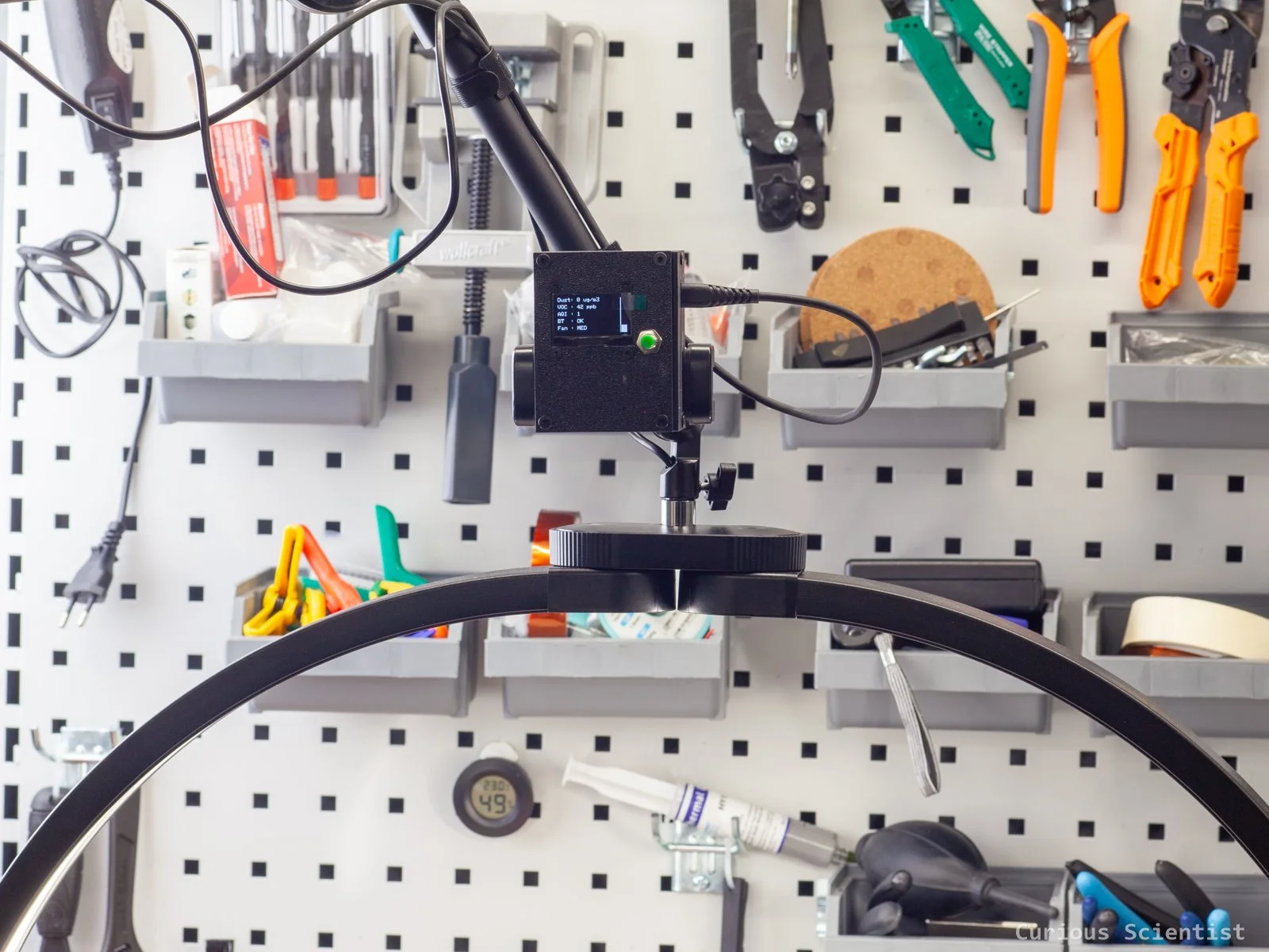
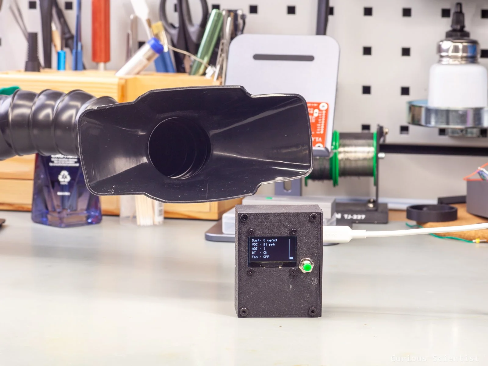
In this article, I continue the development of my remote-controlled fume extractor. Earlier, I showed how I modified my fume extractor so it can be controlled with a Bluetooth remote controller. This allowed me to avoid climbing under my desk every time I need to press the cumbersome switch on its front panel. Now I take the automation a few steps further. I built an air quality sensor based on some parts I already had at home to automatically detect when the air is getting bad and then turn on the fume extractor. The detection is based on a dust sensor and a VOC sensor. Their combined output decides whether the fume extractor should be turned on and at what level it should be running. Due to these two extra detectors and the display I added to the system, the CH32 microcontroller with the separate Bluetooth module was no longer enough, so I switched to an ESP32-C3 Super Mini development board.
Introduction
The basic idea is that when I solder, either with a soldering iron, a hot air tool, or a hot plate, fumes are released by the flux. These fumes can be irritating for the airways, and it is definitely not good for the body in the long term. So, it must be removed from the air before it reaches the lungs. I have a fume extractor for this very purpose. It works well thanks to its multi-layer filter and strong fan. Turning it on and off, however, can be a pain in the ass, and that’s why I added the Bluetooth remote function to it earlier. Despite the upgrade, I was still sometimes lazy to turn it on because I just did a quick soldering job, or I was just simply lazy (and negligent). I have an air purifier in my room, and every time I soldered, it started running at maximum level. This was a sign that I should take things more seriously. Therefore, I upgraded the circuit to turn the fume extractor on automatically, so I am forced to use it. Sort of.
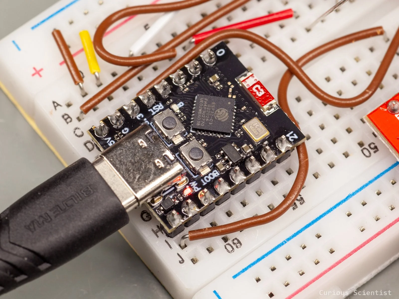
So, now the circuit revolves around an ESP32-C3 Super Mini development board. It is an excellent board for this purpose for several reasons:
It has SPI and I2C peripheral connections available so I can operate the display and the VOC detector easily
It has built-in Bluetooth and even WiFi capability, so I can use it as a remote controller
Even after connecting the VOC detector and the display, I still have enough pins for the dust sensor and an additional button
Actually, originally, I wanted to keep the Bluetooth module from the remote controller and build everything around it using an Arduino Nano. Then, I was annoyed by the USB connector of the Arduino, and some other things, so I just grabbed the ESP32 microcontroller with a USB-C connector, with much better performance and built-in wireless capabilities.
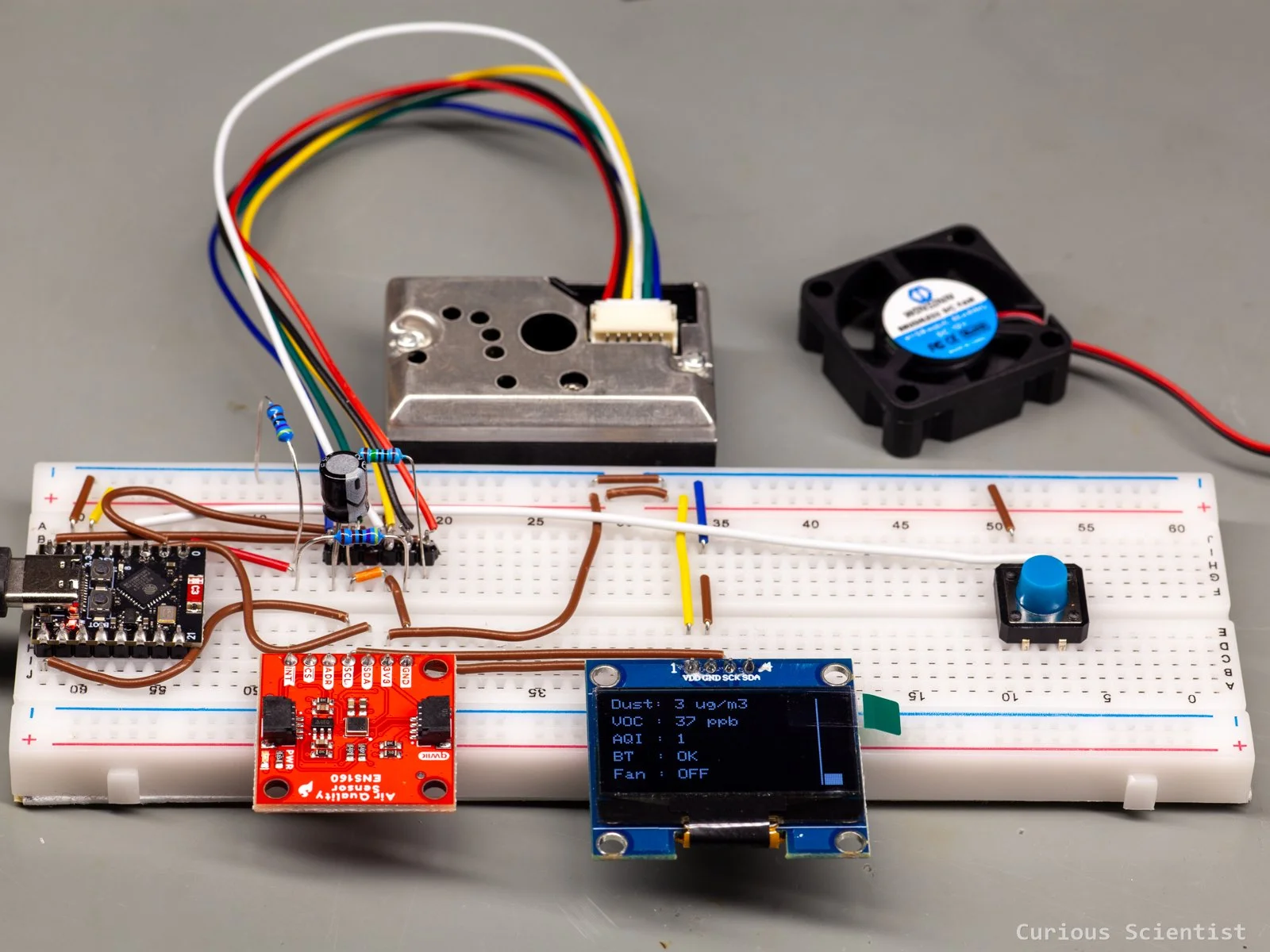
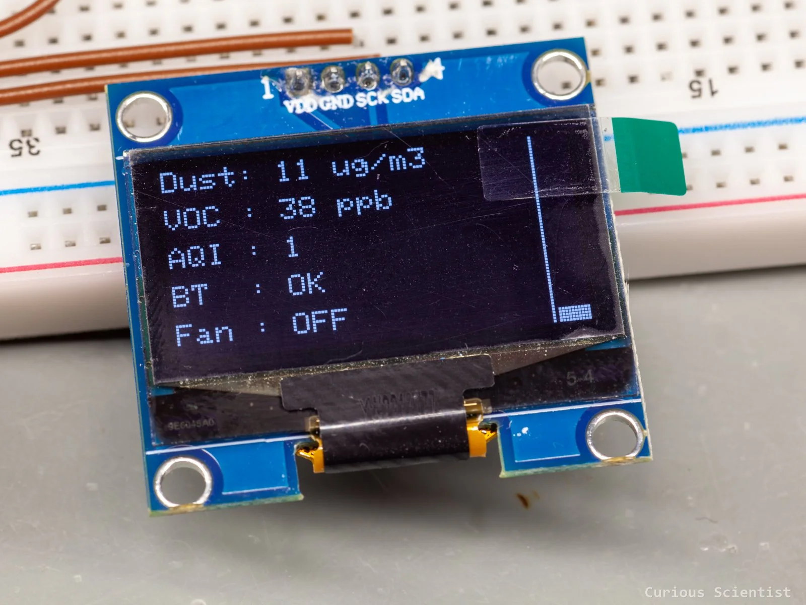
The display is a 1.3” OLED display. It connects to the microcontroller via I2C. The display is driven by the SSH1106 driver, so it is easy to find a compatible Arduino library for it. I used this display because it has been sitting in the drawer for a long time.
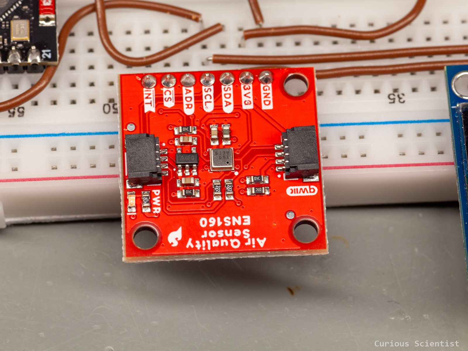
The VOC detector was originally an older CCS811 board. I had this board at home, so I started working with this one. Unfortunately, or luckily, I managed to fry the board. Due to the messy wiring on the breadboard and being tired, I fed the supply voltage to the module’s ground pin, and I managed to brick it. So, I quickly got an ENS160 sensor from my local supplier. I bought the last item from their stock, so I could buy it with a nice discount. The sensor has the same principles as the CCS811, but it is more modern. I use the board to detect VOCs. It is great because fumes can increase the VOC levels, but especially IPA can, which I extensively use when I clean the boards or components, and its fumes are also not that good to breathe in.
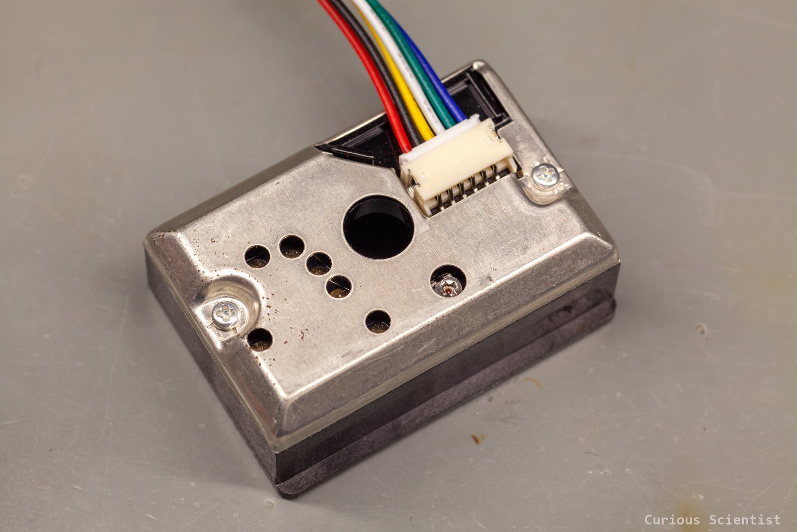
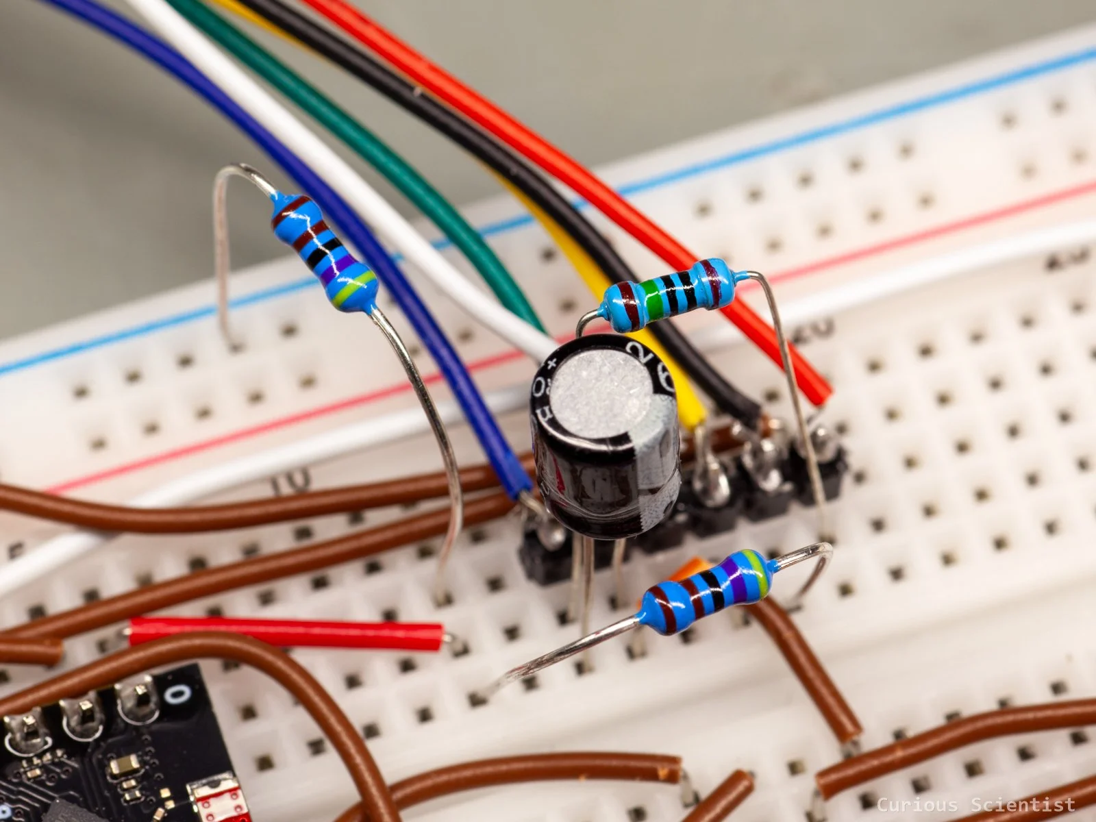
The dust detector is a GP2Y1010AU0F optical dust sensor. I have some earlier videos where I used this sensor. Its working principles are relatively simple. There is an infrared LED inside the metal box that is briefly turned on by the microcontroller. The light emitted by the LED gets scattered by the particles present in the air, and then this scattered light is captured by a sensor (photodiode). The output signal of the device is proportional to the amount of dust present in the sensor, so with some calibration, one can tell how polluted the air is. The sensor is very sensitive to the suspended particles in the fumes created during soldering.
I kept the idea of having a button so I can turn the device on or off manually if needed.
Implementation
First, I put everything together on a breadboard. I wanted to make sure that everything communicates with the microcontroller. I also put together the software and tweaked its behaviour while everything was on the breadboard.
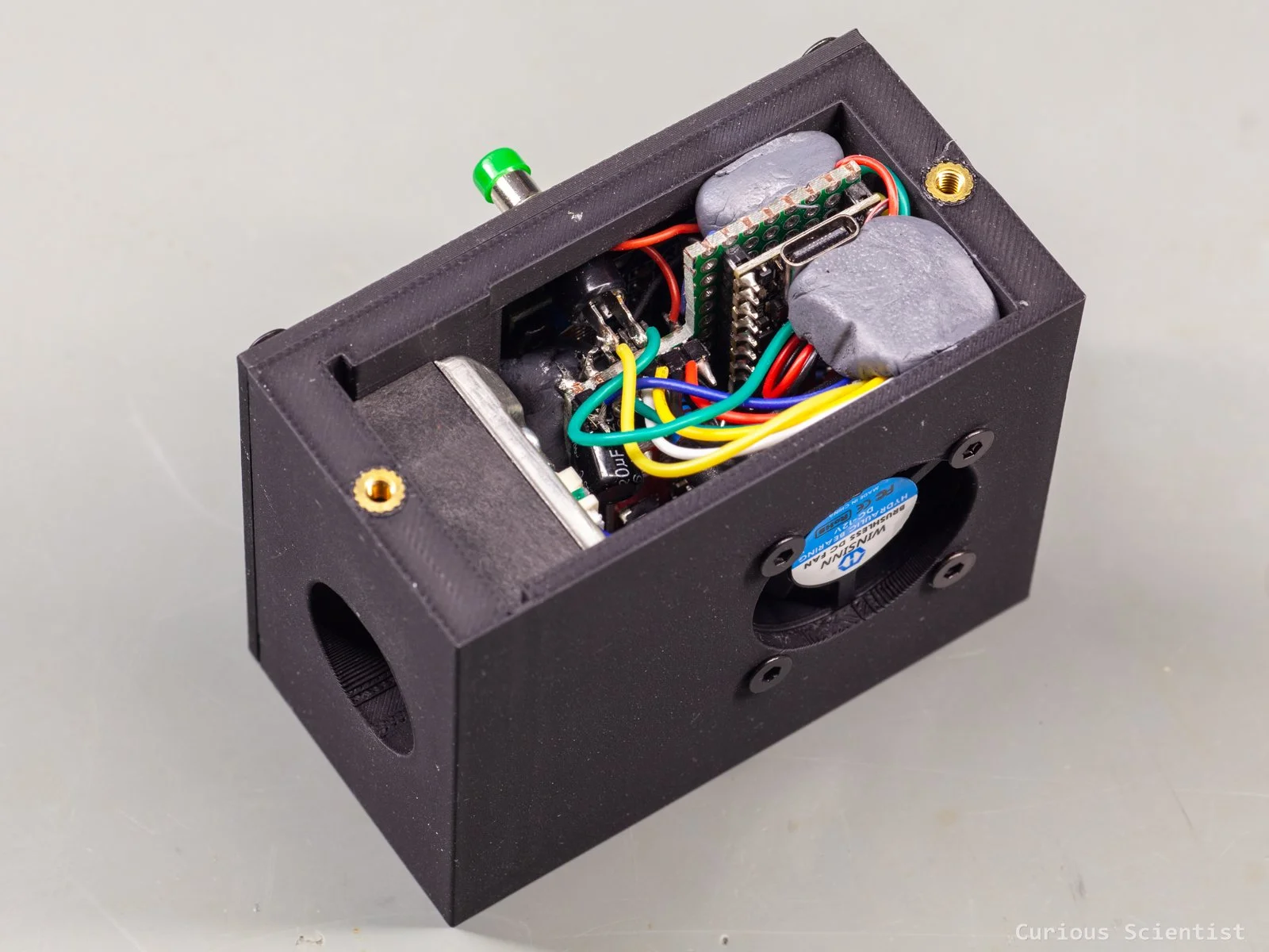
Then, I moved everything into a 3D-printed enclosure. The main dimensions of the enclosure were dictated by the dimensions of the dust sensor. I wanted a relatively small device, but I also had to make sure that the air could pass through it properly, so the contamination gets detected quickly. After a little thinking, I added a 12 V fan to the enclosure that pulled the air through the device, ensuring that both the dust sensor and the VOC sensor are properly exposed to the air and the pollutants don’t settle in the sensor and give false readings. I picked a 12 V, and not a 5 V, fan on purpose. The fan is still running at 5 V, but at a much lower speed, so it is totally silent. Yet, it produces enough airflow to avoid still air in the detector chamber.
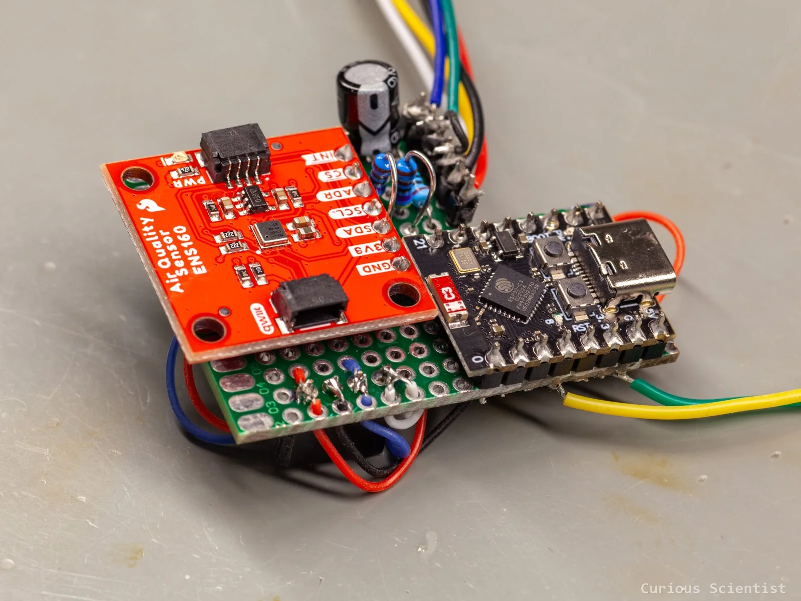
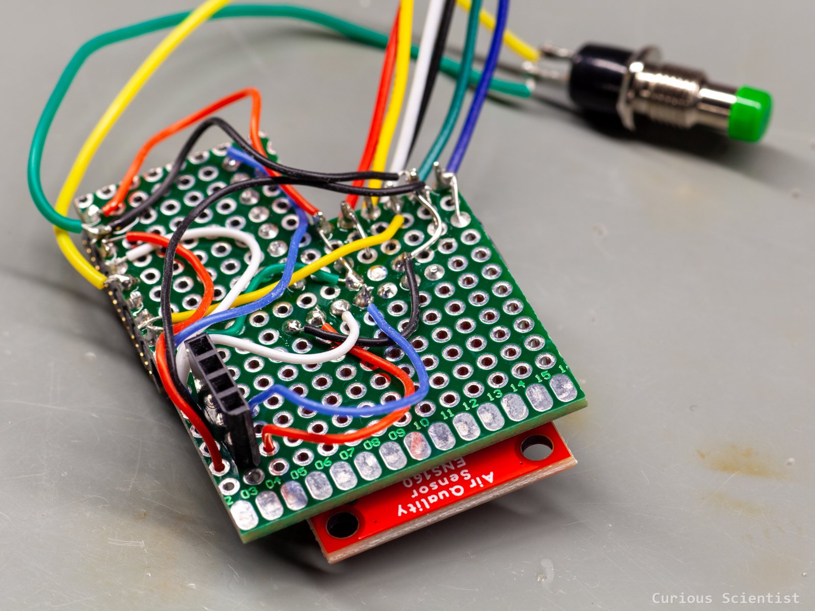
I did not want to bother designing a PCB for this purpose, because the application is so unique that probably no one else would benefit from such a niche PCB. So, everything is assembled on a wonky perfboard.
The whole circuit revolves around the front panel and the display mounted in it. The display holds the circuit board I made out of a perfboard. Then, all the components are mounted on the front side of the board. I just directly soldered everything on the board and then connected everything by permanently soldering the pins and wires together. Ugly job, but it works perfectly for a one-off module. Thanks to the small footprint of the microcontroller, I could squeeze everything onto a relatively small board. Actually, I could have decreased the size even more, but I did not want to miniaturise everything. I wanted to somewhat enjoy assembling the board.
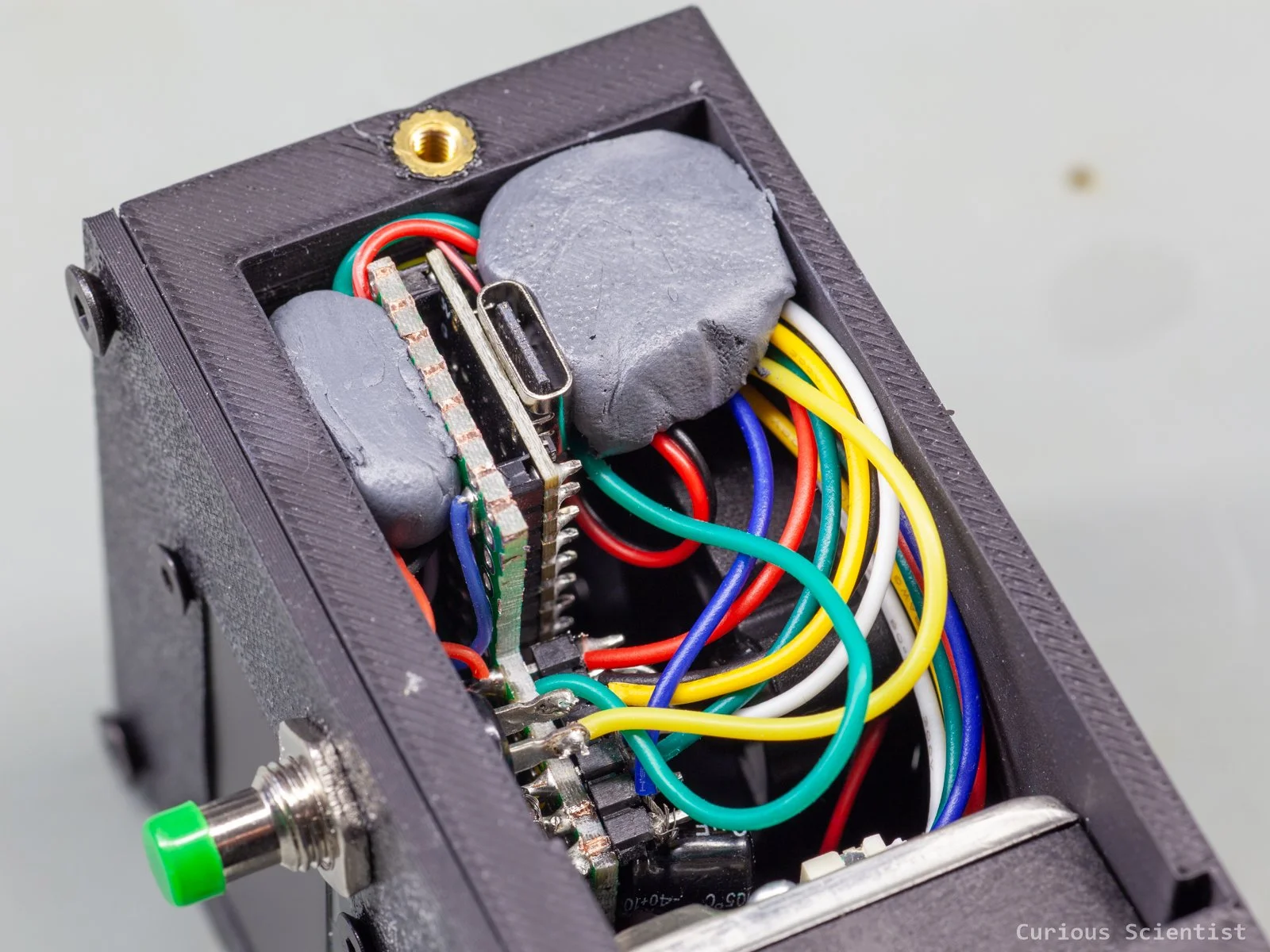
Both the front panel with the OLED display and the button and the side panel with the USB-C connector access are held in place by screws. So, I used some brass insert nuts to allow a solid connection for the panels.
The final assembly steps involved a little cheating, let’s say. I used some clay epoxy to hold the board, especially around the USB-C connector, in place. Since the whole perfboard is just hanging on the display, I wanted to make sure that there is some more support. The perfboard was somewhat improvised in terms of shape and dimensions, so I needed something that I could modify “in-situ” and make a solid support for the electronics. Therefore, I used clay epoxy. It is a great way of fixing DIY stuff permanently.
Operation and testing
The device will hang above my head, attached to the overhead lamp. It is constantly powered from a USB adapter that is always on when I am at the desk. Consequently, the device is also always on, so it is unavoidable to use it unless I unplug it.
The pollution detection is a 2-step detection: it is based on the readings from the dust sensor and the readings from the VOC sensor. None of these readings is based on absolute, known values. I had to sit at the desk and use different devices and equipment to observe a baseline value. I can kick up dust by cleaning up, and I can increase the VOC readings just by breathing on the sensor. Since none of these events should trigger the fume extractor, I studied the behaviour of the setup to determine some baseline values. The VOC sensor reacts to many things besides soldering fumes. Even breathing near it can disturb the readings. So instead of using the raw TVOC value directly, I use a slowly adapting baseline and look for significant increases above it.
I also added a function that does not let the circuit trigger immediately on a single event or threshold violation. There should be several readings over the threshold within a fixed number of readings (3/5 for LOW, 12/20 for MED, and 15/25 for HIGH fan speed) to trigger the fume extractor. This helps to avoid false triggering. The controller reacts quickly by starting at LOW, but it only increases the fan speed if the pollution persists long enough to prove that the lower speed isn't keeping up.
The device can distinguish (empirical) pollution levels. Based on the pollution level, it might switch the fume extractor to a higher level to make the pollution disappear. The pollution is continuously monitored, and if it does not improve, the software sends a signal to the fume extractor to increase fan speed. On the other hand, if there’s no pollution detected for more than 3 minutes, the fume extractor is switched off. The device remembers when the last pollution event was, and it counts down from there. If, let’s say, a pollution signal comes during this 3-minute countdown period, the counter is reset to 3 minutes again. Just in case I want to keep the fan on, even though there’s nothing polluting the air, the device shows a warning message in the last 30 seconds of the 3-minute countdown. If I press the button during these 30 seconds, the device resets the countdown timer.
And sure, if I want, I can just switch the device on or off, and change the fan speed arbitrarily using the button. But the main controller is the sensors. So, if I turn the device off with the button and the pollution increases, the device automatically turns back on. This is my choice, because I want the gadget to force me to use the extractor when the air is bad.
The values that control the fan level and some other parameters are shown on the display. The first parameter is called dust, and it is the particulate reading from the dust sensor shown in ug/m3 units. The lowest trigger level is 40 ug/m3. The next value is the VOC, which is derived from the ENS160 sensor’s readings and is shown in ppb (parts per billion) units. This value is used a bit differently because of its sensitivity to CO2 levels in my room. It reacts if there is a noticeable deviation from the continuously adjusted baseline value. The AQI (air quality index) value is also fetched from the ENS160 sensor. It is the sensor’s own parameter between 1 and 5. This parameter only serves as information; there’s no decision-making done based on it, and it does not affect the status bar. Then the BT line shows the status of the Bluetooth connection. It shows two dashes when the receiver is not found, and it shows OK when it is connected. Finally, the line “Fan” shows the state of the controller. It mirrors the fan’s current level. I also added the 180 s (3 minutes) countdown to the right side of this line so one can see the time left until the expected auto-shutdown of the fan.
On the right side of the display, there is a vertical bar that is my own combined air-quality indicator. It is based on the combination of the dust sensor readings and the VOC readings. The values and levels are empirical; I adjusted them to my room’s air quality and to the pollution levels during work, such as cleaning or soldering. The height of the bar matches the level of pollution and the corresponding extraction level. So, a full bar is shown when the pollution level is over the threshold level that would trigger the fan to run at full speed.
So, with this, I have a properly tuned air quality instrument that can help me breathe in better air during soldering or other processes where dust and fumes can be expected. The VOC and dust sensors nicely complement each other, so different kinds of pollutants can trigger the fume extraction. The device triggers automatically, which saves me from a little work, and it helps me to avoid being lazy and not turning on the fume extractor.