AS5600 Magnetic encoder - A practical example
In this video, I continue discovering the AS5600 magnetic position encoder and its applicability in different scenarios. I rotated a stepper motor by providing pulses with a CNC handwheel and measured the angular displacement of the shaft. I wanted to compare the number of "theoretical steps" with the actually done steps and it seems that they are the same. Of course, I did not go too fast and there was no load on the shaft. Nevertheless, it seems that the motor did not skip any steps and it behaved according to the microstepping settings.
Schematics
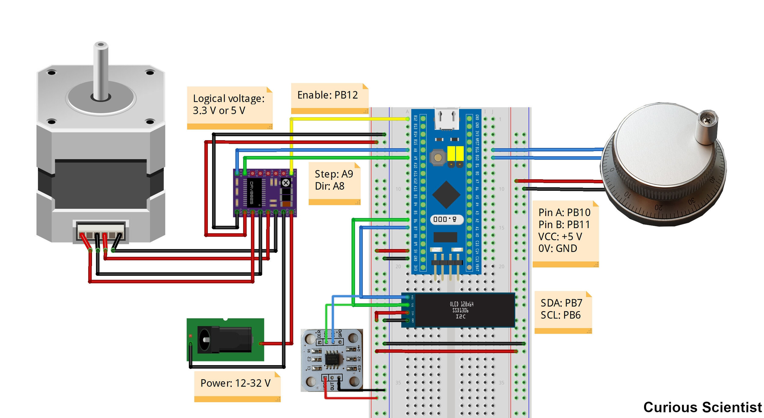
Note: If you see fluctuating values, connect the DIR pin of the AS5600 to ground (GND).
Source code
#include <Wire.h> //This is for i2C
#include <SSD1306Ascii.h> //i2C OLED
#include <SSD1306AsciiWire.h> //i2C OLED

// i2C OLED
#define I2C_ADDRESS 0x3C
#define RST_PIN -1
SSD1306AsciiWire oled;
float OLEDTimer = 0; //Timer for the screen refresh
//I2C pins:
//STM32: SDA: PB7 SCL: PB6
//Arduino: SDA: A4 SCL: A5

//---------------------------------------------------------------------------
//Magnetic sensor things
int magnetStatus = 0; //value of the status register (MD, ML, MH)

int lowbyte; //raw angle 7:0
word highbyte; //raw angle 7:0 and 11:8
int rawAngle; //final raw angle
float degAngle; //raw angle in degrees (360/4096 * [value between 0-4095])

int quadrantNumber, previousquadrantNumber; //quadrant IDs
float numberofTurns = 0; //number of turns
float correctedAngle = 0; //tared angle - based on the startup value
float startAngle = 0; //starting angle
float totalAngle = 0; //total absolute angular displacement
float previoustotalAngle = 0; //for the display printing
float encoderTimer = 0;
//---------------------------------------------------------------------------
int pinA = PB10; // Pin A of the encoder
int pinB = PB11; // Pin B of the encoder

//CNC Decoder behavior
//CW rotation: output of B is half square wave delayed from output of A
//CCW rotation: output of A is half square wave delayed from output of B

//The pulse generator's output can be DIRECTLY wired to the step and dir pins.
//This means that the microcontroller can be omitted!!! - of course there won't be any feedback then

volatile int numberofclicks = 0; //Stores the number of click done by the encoder. 1 turn = 100 clicks
int previous_numberofclicks = 0; //Stores the "previous" number of clicks. Helps us to see if the encoder was moved


//--Stepper motor related----------------------------------------------------------
#include <AccelStepper.h>
AccelStepper stepper(1, PA9, PA8);// pulses/steps 9; Direction 8
const int stepperEnablePin = PB12;  //enable/disable pin for the stepper motor driver
//remember that for Arduino, you don't need the "PA" and "PB" prefixes. Just use 1,2,3...etc.

void setup()
{
  pinMode(pinA, INPUT_PULLUP); //A terminal of the CNC wheel
	pinMode(pinB, INPUT_PULLUP); //B terminal of the CNC wheel

	attachInterrupt(digitalPinToInterrupt(pinA), pinAInterrupt, RISING); //pin A is an interrupt

  Serial.begin(115200); //start serial - tip: don't use serial if you don't need it (speed considerations)
  Wire.begin(); //start i2C
	Wire.setClock(800000L); //fast clock
  //General remark on i2C: it seems that the i2C interferes with the attachInterrupt() in some way causing
  //strange readings if the i2C-related hardware is read too often (in every loop iteration).

  checkMagnetPresence(); //check the magnet (blocks until magnet is found)

  ReadRawAngle(); //make a reading so the degAngle gets updated
  startAngle = degAngle; //update startAngle with degAngle - for taring

  //------------------------------------------------------------------------------
  //OLED part
  #if RST_PIN >= 0
  	oled.begin(&Adafruit128x32, I2C_ADDRESS, RST_PIN);
  #else // RST_PIN >= 0
  	oled.begin(&Adafruit128x32, I2C_ADDRESS);
  #endif // RST_PIN >= 0

	oled.setFont(Adafruit5x7);
	oled.clear(); //clear display
	oled.set2X(); //double-line font size - better to read it
  oled.println("Welcome!"); //print a welcome message
  oled.println("AS5600"); //print a welcome message

  //Stepper setup---------------------------------------------------------
	stepper.setSpeed(1000); //SPEED = Steps / second
	stepper.setMaxSpeed(1000); //SPEED = Steps / second
	stepper.setAcceleration(5000); //ACCELERATION = Steps /(second)^2
	pinMode(stepperEnablePin, OUTPUT); //enable/disable pin is defined as an output
	digitalWrite(stepperEnablePin, LOW); //enable motor current
	//disabling the current can prevent the driver and the motor running hot
	//on the other hand, it can lead to inaccuracies because the motor is not held at place when it is not under power
  delay(2000);
	OLEDTimer = millis(); //start the timer
  encoderTimer = millis(); //start encoder timer

}

void loop()
{
  if(millis()- encoderTimer > 125) //125 ms will be able to make 8 readings in a sec which is enough for 60 RPM
  {
    ReadRawAngle(); //ask the value from the sensor
    correctAngle(); //tare the value
    checkQuadrant(); //check quadrant, check rotations, check absolute angular position

    encoderTimer = millis();

    /*A little brainstorm on determining the required delay
     * The above 3 functions require about 300-310 us to finish
     * They mess up the interrupt of the CNC encoder due to the i2C communication
     * Therefore it is not good if they are called very often
     * We want to detect at least every rotations of the shaft
     * I say (arbitrarily), that we need to detect at least 2 angles in each quadrants, so in 1 turn of the shaft, there are 8 readings
     * 8 readings per turn can be converted into readings per second based on the expected highest speed
     * Example:
     * 60 RPM = 60/60 RPS (rounds per seconds) = 1 RPS
     * 1 round per second -> 8 reading per second -> 1 second/8 readings = 0.125 s = 125 ms is the frequency of readings
     *
     * Example 2:
     *
     * 100 RPM = 100/60 = 1.667 RPS
     * 1 round = 0.599 s -> 0.599 s/ 8 readings = 74.98 ~ 75 ms.
     * Check: 60/100 = 0.6 -> 75/125 = 0.6.
     */

  }

  refreshDisplay(); //refresh the display - won't refresh until certain conditions are not fulfilled

	while (stepper.distanceToGo() != 0) //This blocks the rest of the code!
	{
		stepper.runSpeedToPosition(); //Runs to the target position defined by the moveTo() function
    //does not use accelerations
	}

}

void ReadRawAngle()
{
  //7:0 - bits
  Wire.beginTransmission(0x36); //connect to the sensor
  Wire.write(0x0D); //figure 21 - register map: Raw angle (7:0)
  Wire.endTransmission(); //end transmission
  Wire.requestFrom(0x36, 1); //request from the sensor

  while(Wire.available() == 0); //wait until it becomes available
  lowbyte = Wire.read(); //Reading the data after the request

  //11:8 - 4 bits
  Wire.beginTransmission(0x36);
  Wire.write(0x0C); //figure 21 - register map: Raw angle (11:8)
  Wire.endTransmission();
  Wire.requestFrom(0x36, 1);

  while(Wire.available() == 0);
  highbyte = Wire.read();

  //4 bits have to be shifted to its proper place as we want to build a 12-bit number
  highbyte = highbyte << 8; //shifting to left
  //What is happening here is the following: The variable is being shifted by 8 bits to the left:
  //Initial value: 00000000|00001111 (word = 16 bits or 2 bytes)
  //Left shifting by eight bits: 00001111|00000000 so, the high byte is filled in

  //Finally, we combine (bitwise OR) the two numbers:
  //High: 00001111|00000000
  //Low:  00000000|00001111
  //      -----------------
  //H|L:  00001111|00001111
  rawAngle = highbyte | lowbyte; //int is 16 bits (as well as the word)

  //We need to calculate the angle:
  //12 bit -> 4096 different levels: 360° is divided into 4096 equal parts:
  //360/4096 = 0.087890625
  //Multiply the output of the encoder with 0.087890625
  degAngle = rawAngle * 0.087890625;

  //Serial.print("Deg angle: ");
  //Serial.println(degAngle, 2); //absolute position of the encoder within the 0-360 circle

}

void correctAngle()
{
  //recalculate angle
  correctedAngle = degAngle - startAngle; //this tares the position

  if(correctedAngle < 0) //if the calculated angle is negative, we need to "normalize" it
  {
  correctedAngle = correctedAngle + 360; //correction for negative numbers (i.e. -15 becomes +345)
  }
  else
  {
    //do nothing
  }
  //Serial.print("Corrected angle: ");
  //Serial.println(correctedAngle, 2); //print the corrected/tared angle
}

void checkQuadrant()
{
  /*
  //Quadrants:
  4  |  1
  ---|---
  3  |  2
  */

  //Quadrant 1
  if(correctedAngle >= 0 && correctedAngle <=90)
  {
    quadrantNumber = 1;
  }

  //Quadrant 2
  if(correctedAngle > 90 && correctedAngle <=180)
  {
    quadrantNumber = 2;
  }

  //Quadrant 3
  if(correctedAngle > 180 && correctedAngle <=270)
  {
    quadrantNumber = 3;
  }

  //Quadrant 4
  if(correctedAngle > 270 && correctedAngle <360)
  {
    quadrantNumber = 4;
  }
  //Serial.print("Quadrant: ");
  //Serial.println(quadrantNumber); //print our position "quadrant-wise"

  if(quadrantNumber != previousquadrantNumber) //if we changed quadrant
  {
    if(quadrantNumber == 1 && previousquadrantNumber == 4)
    {
      numberofTurns++; // 4 --> 1 transition: CW rotation
    }

    if(quadrantNumber == 4 && previousquadrantNumber == 1)
    {
      numberofTurns--; // 1 --> 4 transition: CCW rotation
    }
    //this could be done between every quadrants so one can count every 1/4th of transition

    previousquadrantNumber = quadrantNumber;  //update to the current quadrant

  }
  //Serial.print("Turns: ");
  //Serial.println(numberofTurns,0); //number of turns in absolute terms (can be negative which indicates CCW turns)

  //after we have the corrected angle and the turns, we can calculate the total absolute position
  totalAngle = (numberofTurns*360) + correctedAngle; //number of turns (+/-) plus the actual angle within the 0-360 range
  //Serial.print("Total angle: ");
  //Serial.println(totalAngle, 2); //absolute position of the motor expressed in degree angles, 2 digits
}

void checkMagnetPresence()
{
  //This function runs in the setup() and it locks the MCU until the magnet is not positioned properly

  while((magnetStatus & 32) != 32) //while the magnet is not adjusted to the proper distance - 32: MD = 1
  {
    magnetStatus = 0; //reset reading

    Wire.beginTransmission(0x36); //connect to the sensor
    Wire.write(0x0B); //figure 21 - register map: Status: MD ML MH
    Wire.endTransmission(); //end transmission
    Wire.requestFrom(0x36, 1); //request from the sensor

    while(Wire.available() == 0); //wait until it becomes available
    magnetStatus = Wire.read(); //Reading the data after the request

    //Serial.print("Magnet status: ");
    //Serial.println(magnetStatus, BIN); //print it in binary so you can compare it to the table (fig 21)
  }

  //Status register output: 0 0 MD ML MH 0 0 0
  //MH: Too strong magnet - 100111 - DEC: 39
  //ML: Too weak magnet - 10111 - DEC: 23
  //MD: OK magnet - 110111 - DEC: 55

  //Serial.println("Magnet found!");
  delay(1000);
}

void refreshDisplay()
{
  if (millis() - OLEDTimer > 250) //chech if we will update at every 100 ms
	{
    if(totalAngle != previoustotalAngle || previous_numberofclicks != numberofclicks) //if there's a change in the position*
    //if(previous_numberofclicks != numberofclicks) //if there's a change in the position*
    {
        oled.clear(); //delete the content of the display
        oled.print("M: "); //M: Magnet signal (Degrees)
        oled.println(totalAngle); //print the new absolute position
        oled.print("W: "); //W: Wheel signal (Clicks)
        oled.println(numberofclicks);
        OLEDTimer = millis(); //reset timer
        previoustotalAngle = totalAngle; //update the previous value
        previous_numberofclicks = numberofclicks; //update current position
    }
	}
	else
	{
		//skip
	}
  //*idea: you can define a certain tolerance for the angle so the screen will not flicker
  //when there is a 0.08 change in the angle (sometimes the sensor reads uncertain values)
}

void pinAInterrupt()
{
	//When pin A's wave is detected...

	if (digitalRead(pinB) == 0) //if B is LOW, it means that pin A's wave occured first -> CW rotation occured (I had to change it because of the stepper motor)
	{
		numberofclicks++; //increase value
		//Serial.println(numberofclicks); //do not use delays or prints in the final code, use it only for debugging/developing
	}
	else //if B is HIGH, it means that pin B's wave occured first. So, when pin A has a rising edge, pin B is alreadi high -> CCW rotation
	{
		numberofclicks--; //decrease value
		//Serial.println(numberofclicks);
	}
  //Serial.println(numberofclicks);
  stepper.moveTo(-1*numberofclicks); //Updates the "go to" position of the stepper motor - absolute value
  //The above moveTo() function means that if the numberofclick variable = 936, then the stepper motor will be
  //936 steps away from the origin.
}