300 mm DRO with Arduino (ATTiny85 and Nano)
In this video I show you a nice DRO with a great range (300 mm) and good resolution (0.01 mm).
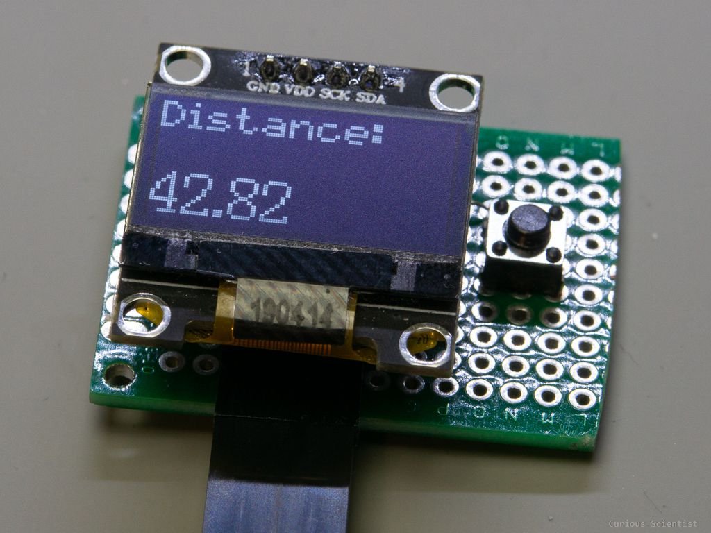
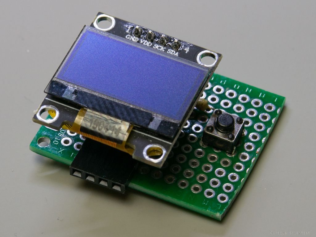
I “hacked” the DRO and was able to hijack its data and clock signal and convert it into human readable values using an ATTiny85 microcontroller. I made my own tiny display unit for this DRO and the principles I used is applicable to similar DROs and digital calipers as well as any Arduino-compatible microcontrollers.
Schematics
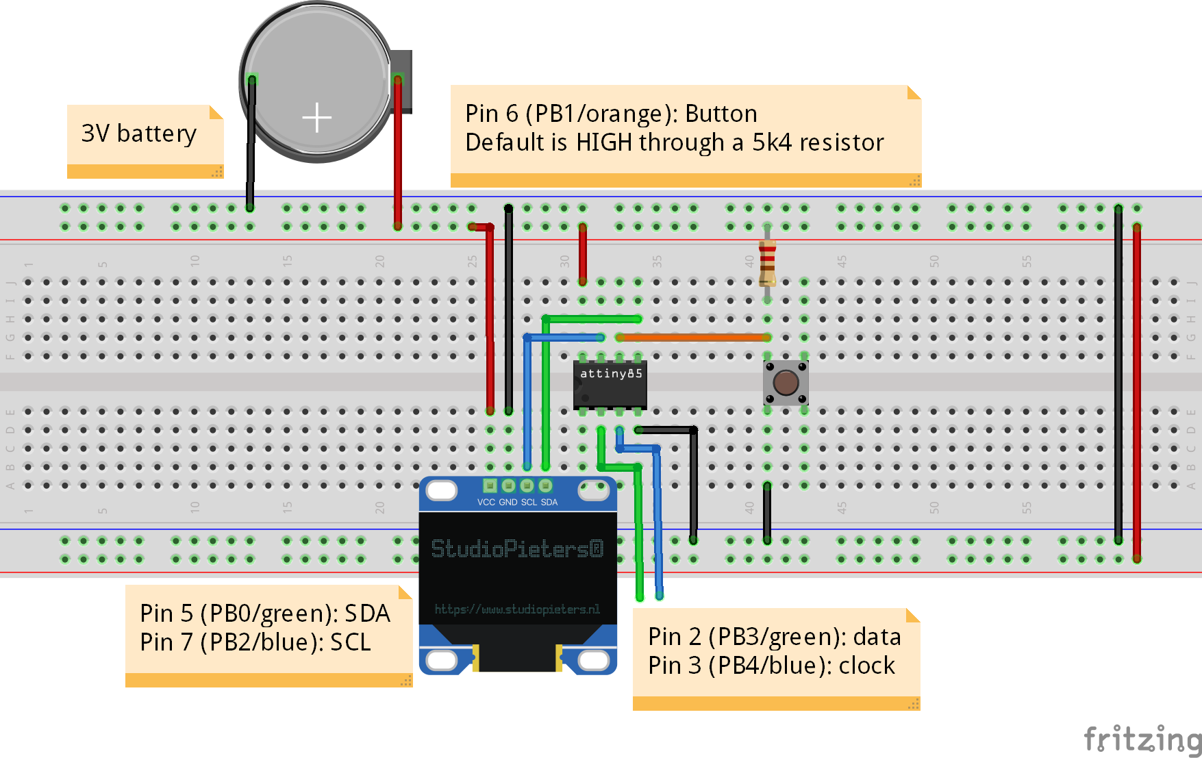
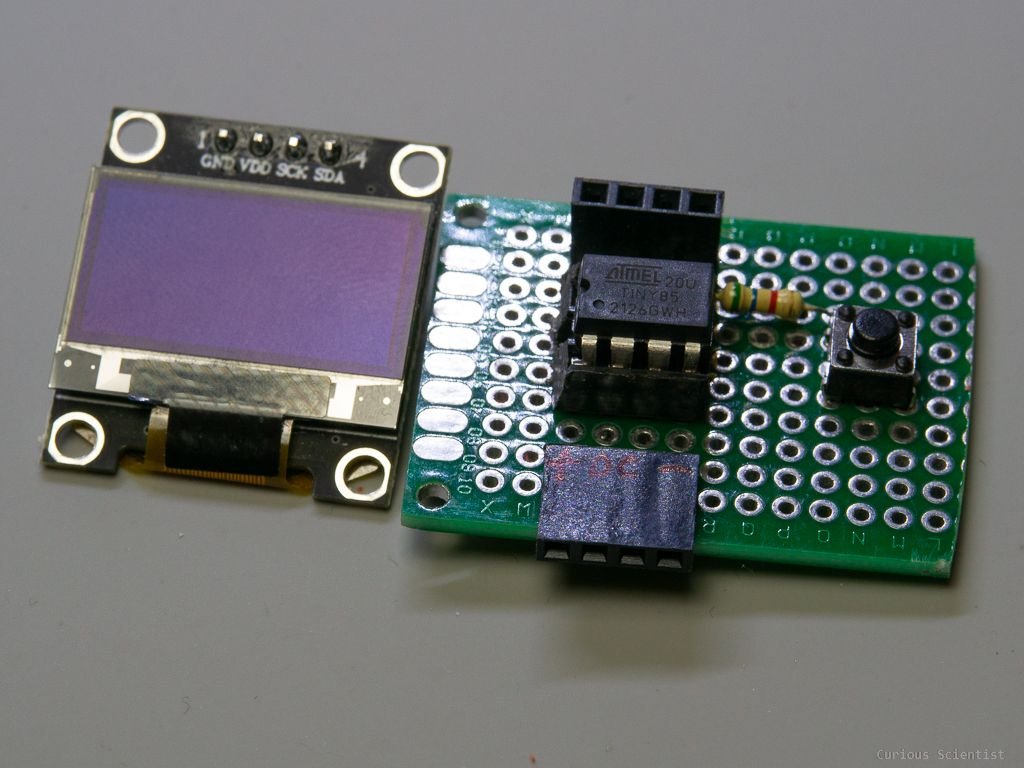
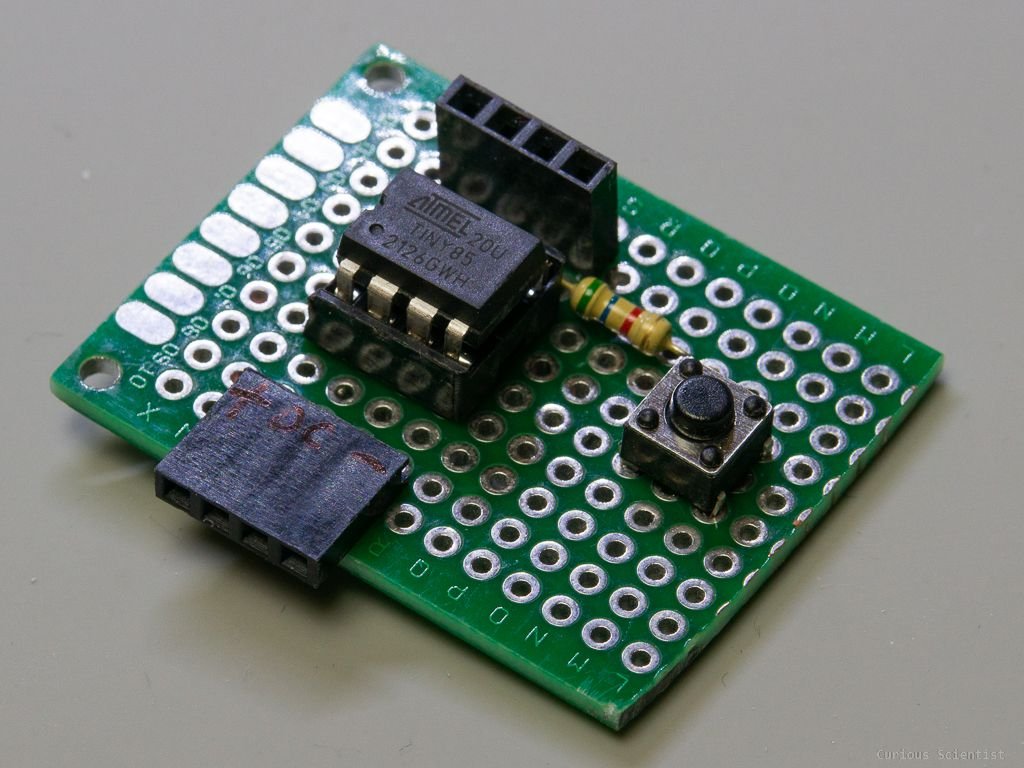
Simple schematics of the circuit I used. Scroll further down to see the pictures of the actual circuit. Keep in mind that the pin names (“Pin 2”, “Pin 3”…etc.) indicate the physical pins whereas the “PB3”, “PB4”…etc. are the “internal pin numbers” which should be used in the Arduino code. Pin 2 (PB3) is connected to the DRO’s data line, and Pin 3 (PB4) is connected to the DRO’s clock line. Of course, the DRO will also require a supply voltage which in my case is the same as of the ATTiny85.
Arduino (ATTiny 85) source code
Notice: I slightly modified the code as compared to the one I showed in the video. Based on some suggestions I improved the synchronization with the clock signal as well as I only refresh the display when the value is changed.
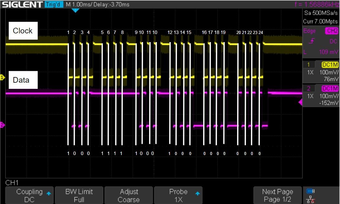
//The code uses the following Attiny85 core: https://github.com/SpenceKonde/ATTinyCore
int dro_bits[24]; //array for the 24 bits
char str[7]; //Array for the char "string"

unsigned long droTimer = 0; //update frequency
unsigned long buttonTimer = 0; //debouncing

int clk = 4; //Blue wire
int data = 3; //Red wire
int button = 1; //button pin

float convertedValue = 0.0;
float resultValue = 0.0;
float previousresultValue = 0.0;
float tareValue = 0.0;

#include <TinyI2CMaster.h>
#include <Tiny4kOLED.h>

void setup()
{
  pinMode(clk, INPUT_PULLUP);
  pinMode(data, INPUT_PULLUP);
  pinMode(button, INPUT_PULLUP);

  oled.begin(128, 64, sizeof(tiny4koled_init_128x64br), tiny4koled_init_128x64br);
  oled.clear();
  oled.setFontX2(FONT8X16P);
  oled.setCursor(0, 0);
  oled.print("Dist:");
  oled.on();
}

void loop()
{
  readEncoder();
  readButton();
  printLCD();
}

void readButton()
{
  if (digitalRead(button) == 0)
  {
    if (millis() - buttonTimer > 300) //software "debounce"
    {
      tareValue = convertedValue; //use the most recent conversion value as the tare value
      buttonTimer = millis();
    }
  }
}

void printLCD()
{
  //It checks if the value has been changed. If yes, it updates the display.
  if (resultValue != previousresultValue)
  {
    dtostrf(resultValue, 0, 2, str); //float to char[]
    oled.setCursor(0, 4);
    oled.clearToEOL(); //erase the previous value from the display
    oled.setCursor(0, 4);
    oled.print(str); //print the new value
    previousresultValue = resultValue;
  }
}

void readEncoder()
{
  //This function reads the encoder
  //I added a timer if you don't need high update frequency

  if (millis() - droTimer > 1000) //if 1 s passed we start to wait for the incoming reading
  {
    convertedValue = 0; //set it to zero, so no garbage will be included in the final conversion value

    //This part was not shown in the video because I added it later based on a viewer's idea
    unsigned long syncTimer = 0; //timer for syncing the readout process with the DRO's clock signal
    bool synchronized = false; // Flag that let's the code know if the clk is synced
    while (synchronized == false)
    {
      syncTimer = millis(); //start timer
      while (digitalRead(clk) == HIGH) {} //wait until the clk goes low
      //Time between the last rising edge of CLK and the first falling edge is 115.7 ms
      //Time of the "wide high part" that separates the 4-bit parts: 410 us

      if (millis() - syncTimer > 5) //if the signal has been high for more than 5 ms, we know that it has been synced
      { //with 5 ms delay, the code can re-check the condition ~23 times so it can hit the 115.7 ms window
        synchronized = true;
      }
      else
      {
        synchronized = false;
      }
    }

    for (int i = 0; i < 23; i++) //We read the whole data block - just for consistency
    {
      while (digitalRead(clk) == LOW) {} // wait for the rising edge

      dro_bits[i] = digitalRead(data);

      while (digitalRead(clk) == HIGH) {} // wait for the falling edge
    }

    //Reconstructing the real value
    for (int i = 0; i < 20; i++) //we don't process the whole array, it is not necessary for our purpose
    {
      convertedValue = convertedValue + (pow(2, i) * dro_bits[i]);
      //Summing up all the 19 bits.
      //Essentially: 1*[i] + 2*[i] + 4*[i] + 8*[i] + 16 * [i] + ....
    }

    if (dro_bits[20] == 1)
    {
      //don't touch the value (stays positive)
    }
    else
    {
      convertedValue = -1 * convertedValue; // convert to negative
    }

    convertedValue = (convertedValue / 100.0); //conversion to mm
    //Division by 100 comes from the fact that the produced number is still an integer (e.g. 9435) and we want a float
    //The 100 is because of the resolution (0.01 mm). x/100 is the same as x*0.01.

    //The final result is stored in a separate variable where the tare is subtracted
    //We need a separate variable because the converted value changes "on its own scale".
    resultValue = convertedValue - tareValue;

    droTimer = millis();
  }
}
Arduino (Nano) source code
I decided to add a normal Arduino-based code as well so you can use the same code directly without any modifications and optimizations on the popular Arduino boards such as the Arduino Nano or Uno…etc. Enjoy!
//This code is more general, written for Arduino (I tested it with Nano)
int dro_bits[24];        // For storing the data bit. bit_array[0] = data bit 1 (LSB), bit_array[23] = data bit 24 (MSB).
char str[7]; //Array for the char "string"

unsigned long droTimer = 0; //update frequency (the DRO is checked this often)
unsigned long buttonTimer = 0; //debouncing

int clk = 4; //Blue
int data = 5; //Red
int button = 6; //button pin

float convertedValue = 0.0; //raw conversion value (bit to mms)
float resultValue = 0.0; //final result value: conversion value - tare value (if there is any taring)
float previousresultValue = 0.0; //temporary storage to be able to register a change in the value
float tareValue = 0.0; //tare value to set a new zero point anywhere (using a button)

#include <Wire.h>

//--Display---------------------------------------------
#include <Adafruit_GFX.h>
#include <Adafruit_SSD1306.h>

#define SCREEN_WIDTH 128 // OLED display width, in pixels
#define SCREEN_HEIGHT 64 // OLED display height, in pixels
#define OLED_RESET     -1 // Reset pin
Adafruit_SSD1306 display(SCREEN_WIDTH, SCREEN_HEIGHT, &Wire, OLED_RESET);

void setup()
{
  Serial.begin(9600);
  Serial.println("DRO reading Arduino"); //test message to see if the serial works
  pinMode(clk, INPUT_PULLUP);
  pinMode(data, INPUT_PULLUP);
  pinMode(button, INPUT_PULLUP);


  if (!display.begin(SSD1306_SWITCHCAPVCC, 0x3C))
  {
    Serial.println(F("SSD1306 allocation failed"));
    for (;;); // Don't proceed, loop forever
  }

  display.display();
  display.begin(SSD1306_SWITCHCAPVCC, 0x3C);
  display.setTextSize(3);
  display.setTextColor(SSD1306_WHITE);
  display.clearDisplay();     // Clear display
  display.setCursor(0, 0);    // Start at top-left corner
  display.println("Dist:");
  display.display();
  //The text "Dist: " becomes a permanent part of the display
}

void loop()
{
  readEncoder();
  readButton();
  printLCD();
}

void printLCD()
{
  //The display is only updated if the value of the DRO changes.
  if (resultValue != previousresultValue)
  {
    display.setTextSize(3);
    display.setCursor(0, 40);
    display.setTextColor(WHITE, BLACK); //This line together with the next erases the previous number
    display.println("        "); //Print the corresponding current
    display.setTextColor(SSD1306_WHITE);
    display.setCursor(0, 40);
    display.println(resultValue); //Print the corresponding current
    display.display();

    previousresultValue = resultValue; //save the most recent reading
  }
}

void readButton()
{
  if (digitalRead(button) == 0) //The button should pull the circuit to GND! (It is pulled up by default)
  {
    if (millis() - buttonTimer > 300) //software "debounce"
    {
      tareValue = convertedValue; //use the most recent conversion value as the tare value
      buttonTimer = millis();
    }
  }
}

void readEncoder()
{
  //This function reads the encoder
  //I added a timer if you don't need high update frequency

  if (millis() - droTimer > 1000) //if 1 s passed we start to wait for the incoming reading
  {
    convertedValue = 0; //set it to zero, so no garbage will be included in the final conversion value

    //This part was not shown in the video because I added it later based on a viewer's idea
    unsigned long syncTimer = 0; //timer for syncing the readout process with the DRO's clock signal
    bool synchronized = false; // Flag that let's the code know if the clk is synced
    while (synchronized == false)
    {
      syncTimer = millis(); //start timer
      while (digitalRead(clk) == HIGH) {} //wait until the clk goes low
      //Time between the last rising edge of CLK and the first falling edge is 115.7 ms
      //Time of the "wide high part" that separates the 4-bit parts: 410 us

      if (millis() - syncTimer > 5) //if the signal has been high for more than 5 ms, we know that it has been synced
      { //with 5 ms delay, the code can re-check the condition ~23 times so it can hit the 115.7 ms window
        synchronized = true;
      }
      else
      {
        synchronized = false;
      }
    }

    for (int i = 0; i < 23; i++) //We read the whole data block - just for consistency
    {
      while (digitalRead(clk) == LOW) {} // wait for the rising edge

      dro_bits[i] = digitalRead(data);
      //Print the data on the serial
      Serial.print(dro_bits[i]);
      Serial.print(" ");

      while (digitalRead(clk) == HIGH) {} // wait for the falling edge
    }
    Serial.println(" ");

    //Reconstructing the real value
    for (int i = 0; i < 20; i++) //we don't process the whole array, it is not necessary for our purpose
    {
      convertedValue = convertedValue + (pow(2, i) * dro_bits[i]);
      //Summing up all the 19 bits.
      //Essentially: 1*[i] + 2*[i] + 4*[i] + 8*[i] + 16 * [i] + ....
    }

    if (dro_bits[20] == 1)
    {
      //don't touch the value (stays positive)
      Serial.println("Positive ");
    }
    else
    {
      convertedValue = -1 * convertedValue; // convert to negative
      Serial.println("Negative ");
    }

    convertedValue = (convertedValue / 100.0); //conversion to mm
    //Division by 100 comes from the fact that the produced number is still an integer (e.g. 9435) and we want a float
    //The 100 is because of the resolution (0.01 mm). x/100 is the same as x*0.01.

    //The final result is stored in a separate variable where the tare is subtracted
    //We need a separate variable because the converted value changes "on its own scale".
    resultValue = convertedValue - tareValue;

    //Dump everything on the serial
    Serial.print("Raw reading: ");
    Serial.println(convertedValue);
    Serial.print("Tare value: ");
    Serial.println(tareValue);
    Serial.print("Result after taring: ");
    Serial.println(resultValue);
    Serial.println(" ");

    droTimer = millis();
  }
}
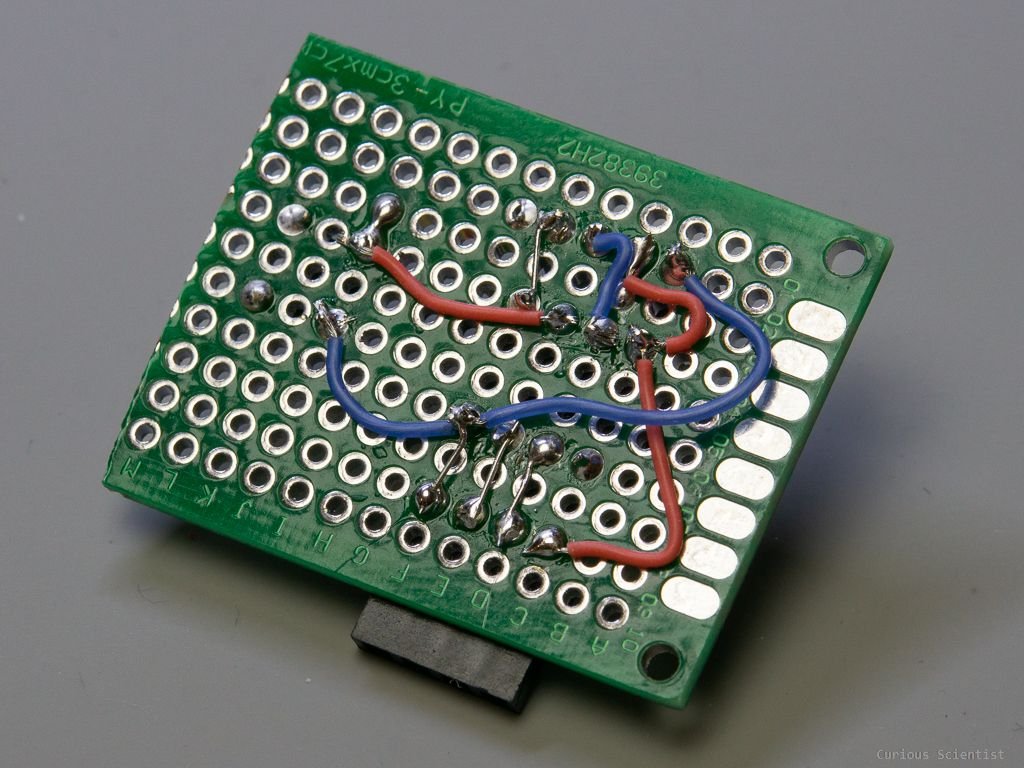
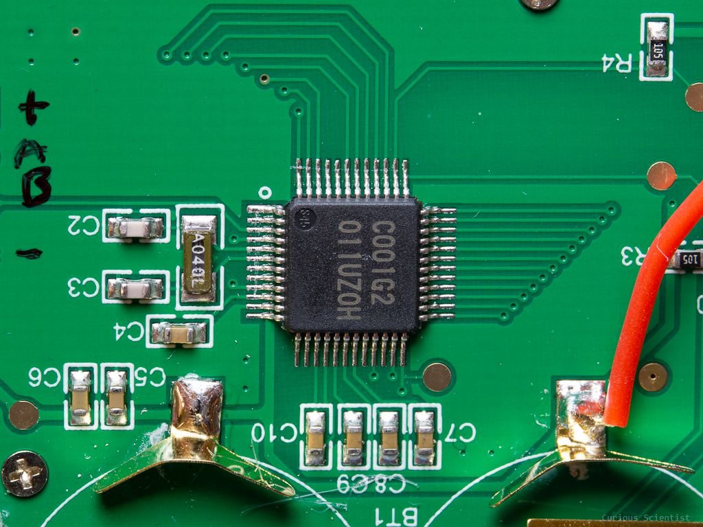
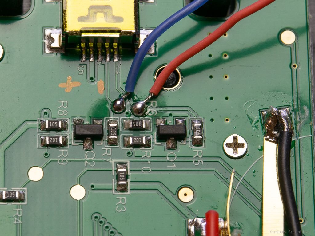
Some additional pictures and information