How I Automated My Metallurgical Microscope
In this video, I show you the finalized version of my motorized microscope system. I added a few little touches to the system as well as adjusted some parameters in the code to achieve a smoother movement and smarter system.
Technical details
Let me briefly summarize the improvements and changes since the last project.
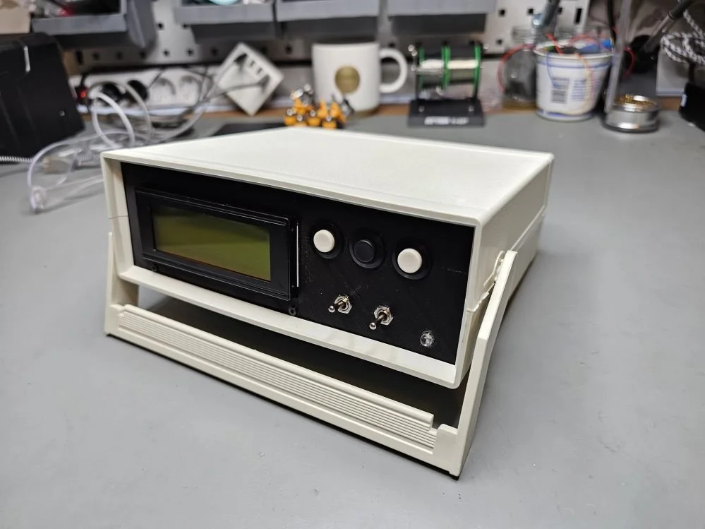
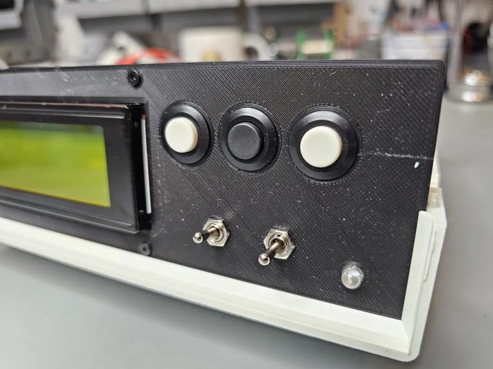
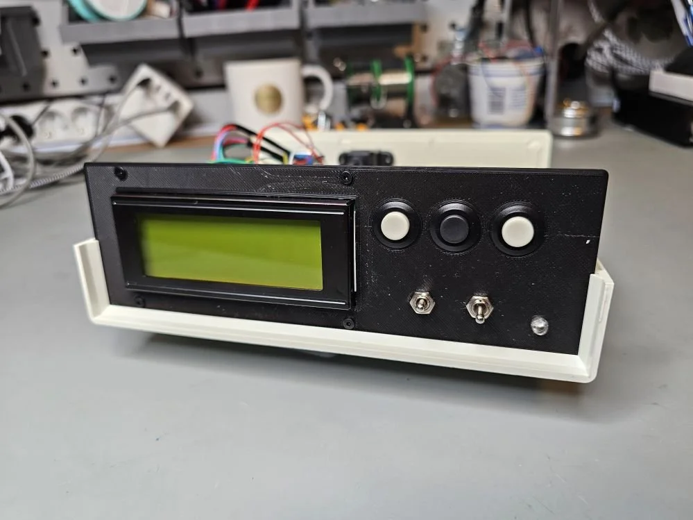
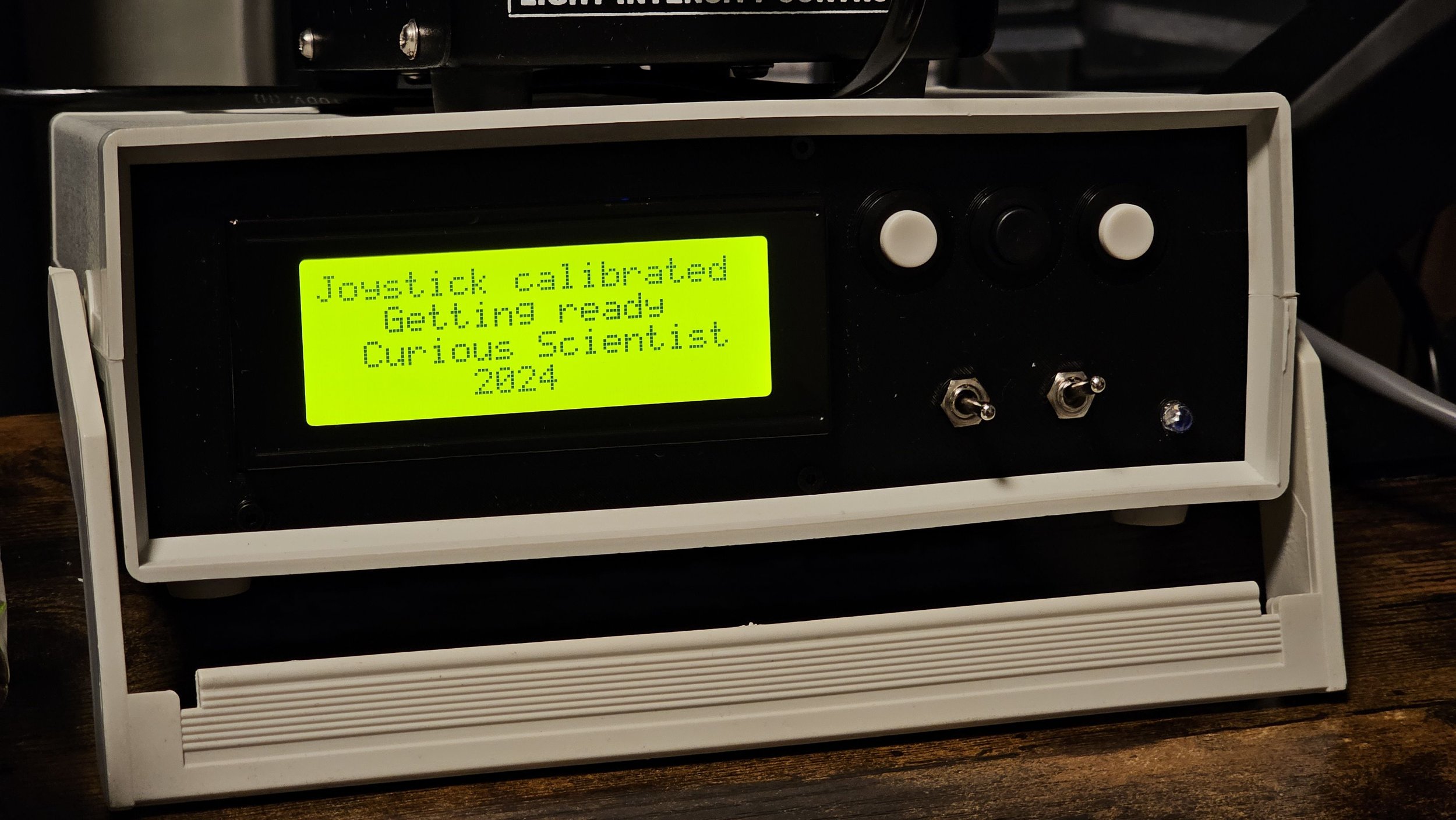
First of all, one of the most obvious changes is that I added a display to the system. It is a “2004 LCD”, it has 4 lines and each line can display 20 characters. The characters are large, the display has a good brightness and contrast and it fits the front panel well. Speaking of the front panel, this is also something that I added as an improvement. Previously, I used the original plastic sheet of the enclosure and I drilled and carved holes in it to accommodate the buttons and switches. However, after 15 minutes of measuring and drawing in Fusion 360, and then after 2 hours of 3d printing, I got a nice and precisely fitted custom front panel.
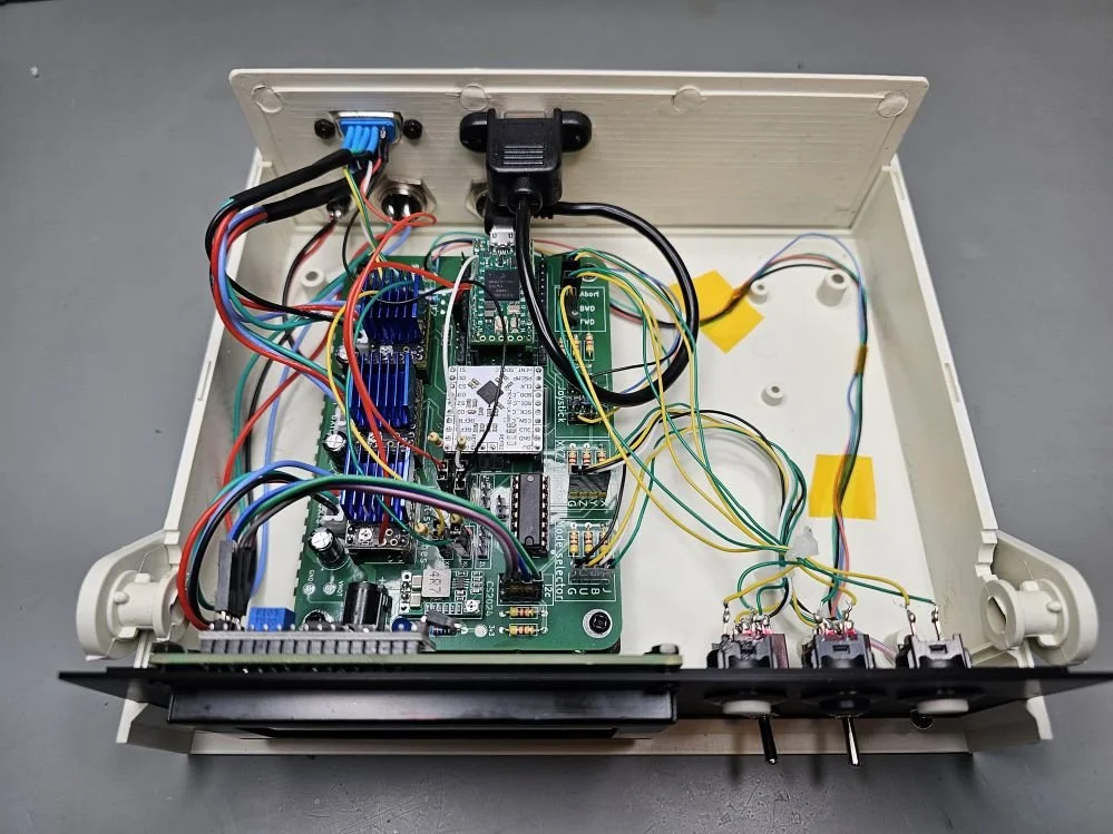
Another hardware-related change is that I added pull-up resistors to the connectors of the limit switches. The reason for this is simple. The limit switches in the stage do not have any pull-up resistors. Therefore I added them so I could use the limit switch function of the TMC429 properly. However, the Z-axis does not have any limit switches, yet I can perform homing with it. Since the motors are driven by TMC2209 drivers, I could use the StallGuard feature and stop the motor upon stalling. So the homing on the Z-axis is done a bit differently. Instead of using a limit switch, I drive the whole Z-axis upwards, until it hits the end of the rail. Since the mechanism (rack and pinion) gets stuck, the motor also stalls at this point. The StallGuard kicks in, stops the motor and then moves it down by 5 mm. This is the home (Z = 0 mm) position of the Z. The X and Y axes have their home position at the geometrical centre of the stage. So when I place a sample in the microscope when it is at its home position, I only need to move along the Z-axis and focus the image.
In the previous project video, I mentioned that the speed settings are far from optimal. This is now fully resolved and all three axes move smoothly and at proper speeds. I also implemented a cool feature. So, in joystick mode, the speed of the stage depends on the position of the joystick arm. The more I tilt the arm, the higher the speed of the stage will be. This is obvious so far. However, if I use the buttons to move the stage, there’s only one speed. I could’ve implemented time-dependent behaviour where the longer I keep the buttons pressed, the faster the stage becomes, but it would’ve been annoying when I wanted to navigate the stage very precisely. So, I chose another path. In joystick mode, the code does not care if the axis-selector toggle switch is in the X, Y or Z position. However, if I change the selection, the code detects the change. It just does not do anything. Or more precisely, it did not do anything until now. Now, depending on the axis selection in joystick mode, a multiplier value is applied in button mode. When the X-axis is selected, the multiplier is 1, so there’s no change to the speed. The default speed of each axis is quite low, so even at high magnifications (we are talking about several hundred times!), the movement of the stage looks quite smooth. When the Y-axis is selected in joystick mode, the speed multiplier in the button mode will be 15 times. And when the Z-axis is selected, the multiplier is 50 times.
Just to have an idea of how slow the default speed is in my case, let’s do a quick calculation. The microstepping of the motor is set to 3200 steps/turn. So, it took 3200 steps to rotate the shaft 360°. The lead screw that is attached to the motor has a pitch of 1 mm. This means that 3200 steps will move the stage by 1 mm. The speed on the X and Y axis in the default mode (multiplier = 1) is set to 12 steps/s. So, that is about 12/3200 mm/s speed, or 3.75 um/s. This is roughly 1/10th of the thickness of a human hair per second. And as you see it in the video, the motor can do this without any particular struggling.
Images and resources
Get some of the relevant parts by using my affiliate links
Join my YouTube membership!
Get the PCB from PCBWay: